EP1177863A2 - Rallonge adaptable sur un manche d'outil et pourvu d'un méchanisme pour empêcher sa rotation relative - Google Patents
Rallonge adaptable sur un manche d'outil et pourvu d'un méchanisme pour empêcher sa rotation relative Download PDFInfo
- Publication number
- EP1177863A2 EP1177863A2 EP01115628A EP01115628A EP1177863A2 EP 1177863 A2 EP1177863 A2 EP 1177863A2 EP 01115628 A EP01115628 A EP 01115628A EP 01115628 A EP01115628 A EP 01115628A EP 1177863 A2 EP1177863 A2 EP 1177863A2
- Authority
- EP
- European Patent Office
- Prior art keywords
- pole
- tool
- handle
- extension pole
- extension
- Prior art date
- Legal status (The legal status is an assumption and is not a legal conclusion. Google has not performed a legal analysis and makes no representation as to the accuracy of the status listed.)
- Granted
Links
- 239000003973 paint Substances 0.000 claims abstract description 11
- 238000010276 construction Methods 0.000 description 2
- 230000000994 depressogenic effect Effects 0.000 description 2
- 238000012986 modification Methods 0.000 description 2
- 230000004048 modification Effects 0.000 description 2
- 230000004075 alteration Effects 0.000 description 1
- 238000013459 approach Methods 0.000 description 1
- 230000000295 complement effect Effects 0.000 description 1
- 230000007423 decrease Effects 0.000 description 1
- 230000000694 effects Effects 0.000 description 1
- 230000003028 elevating effect Effects 0.000 description 1
- 230000013011 mating Effects 0.000 description 1
- 238000000926 separation method Methods 0.000 description 1
Images



Classifications
-
- B—PERFORMING OPERATIONS; TRANSPORTING
- B25—HAND TOOLS; PORTABLE POWER-DRIVEN TOOLS; MANIPULATORS
- B25G—HANDLES FOR HAND IMPLEMENTS
- B25G3/00—Attaching handles to the implements
- B25G3/02—Socket, tang, or like fixings
- B25G3/12—Locking and securing devices
- B25G3/18—Locking and securing devices comprising catches or pawls
-
- B—PERFORMING OPERATIONS; TRANSPORTING
- B25—HAND TOOLS; PORTABLE POWER-DRIVEN TOOLS; MANIPULATORS
- B25G—HANDLES FOR HAND IMPLEMENTS
- B25G1/00—Handle constructions
- B25G1/04—Handle constructions telescopic; extensible; sectional
-
- F—MECHANICAL ENGINEERING; LIGHTING; HEATING; WEAPONS; BLASTING
- F16—ENGINEERING ELEMENTS AND UNITS; GENERAL MEASURES FOR PRODUCING AND MAINTAINING EFFECTIVE FUNCTIONING OF MACHINES OR INSTALLATIONS; THERMAL INSULATION IN GENERAL
- F16B—DEVICES FOR FASTENING OR SECURING CONSTRUCTIONAL ELEMENTS OR MACHINE PARTS TOGETHER, e.g. NAILS, BOLTS, CIRCLIPS, CLAMPS, CLIPS OR WEDGES; JOINTS OR JOINTING
- F16B2200/00—Constructional details of connections not covered for in other groups of this subclass
- F16B2200/10—Details of socket shapes
-
- Y—GENERAL TAGGING OF NEW TECHNOLOGICAL DEVELOPMENTS; GENERAL TAGGING OF CROSS-SECTIONAL TECHNOLOGIES SPANNING OVER SEVERAL SECTIONS OF THE IPC; TECHNICAL SUBJECTS COVERED BY FORMER USPC CROSS-REFERENCE ART COLLECTIONS [XRACs] AND DIGESTS
- Y10—TECHNICAL SUBJECTS COVERED BY FORMER USPC
- Y10T—TECHNICAL SUBJECTS COVERED BY FORMER US CLASSIFICATION
- Y10T403/00—Joints and connections
- Y10T403/16—Joints and connections with adjunctive protector, broken parts retainer, repair, assembly or disassembly feature
- Y10T403/1616—Position or guide means
-
- Y—GENERAL TAGGING OF NEW TECHNOLOGICAL DEVELOPMENTS; GENERAL TAGGING OF CROSS-SECTIONAL TECHNOLOGIES SPANNING OVER SEVERAL SECTIONS OF THE IPC; TECHNICAL SUBJECTS COVERED BY FORMER USPC CROSS-REFERENCE ART COLLECTIONS [XRACs] AND DIGESTS
- Y10—TECHNICAL SUBJECTS COVERED BY FORMER USPC
- Y10T—TECHNICAL SUBJECTS COVERED BY FORMER US CLASSIFICATION
- Y10T403/00—Joints and connections
- Y10T403/32—Articulated members
- Y10T403/32254—Lockable at fixed position
- Y10T403/32467—Telescoping members
- Y10T403/32524—Self-locking
-
- Y—GENERAL TAGGING OF NEW TECHNOLOGICAL DEVELOPMENTS; GENERAL TAGGING OF CROSS-SECTIONAL TECHNOLOGIES SPANNING OVER SEVERAL SECTIONS OF THE IPC; TECHNICAL SUBJECTS COVERED BY FORMER USPC CROSS-REFERENCE ART COLLECTIONS [XRACs] AND DIGESTS
- Y10—TECHNICAL SUBJECTS COVERED BY FORMER USPC
- Y10T—TECHNICAL SUBJECTS COVERED BY FORMER US CLASSIFICATION
- Y10T403/00—Joints and connections
- Y10T403/59—Manually releaseable latch type
- Y10T403/598—Transversely sliding pin
Definitions
- the present invention relates generally to extension poles, such as a pole used with a paint roller tool to extend the reach of the tool. More particularly, the present invention relates to an extension pole that is particularly designed for removable connection to a tool handle, wherein the tool-connection end of the pole cooperates with the tool handle to prevent relative rotation and the outer pole surface adjacent the end is flush with the gripping surface handle when the pole and tool are interconnected.
- An extension pole is commonly used in various tool applications to provide access to an area that is difficult to reach (e.g., a high section of a wall that would otherwise not be reachable unless a ladder or some other elevating structure is used).
- a ladder or some other elevating structure is used.
- extension pole applications utilize a connection geometry other than a circular configuration, thereby preventing the relative rotation.
- this type of configuration typically results in the outer surface of the tool handle and extension pole not connecting in a flush manner. The effect of this connection is unattractive and provides a less comfortable grip for the user.
- an important object of the present invention is to provide an improved extension pole that extends the reach of a tool attached to the pole. It is also an important object of the present invention to provide an extension pole configured to cooperate with the tool handle in preventing relative rotation therebetween. In addition, an important object of the present invention is to provide an extension pole that cooperates with the tool handle when providing a smooth, continuous and comfortable outer surface. Yet another important object of the present invention to provide an extension pole that has an inexpensive, durable and simple construction. It is a further object of the present invention to provide an extension pole that has a smooth and comfortable grip that is attractive to the user.
- the present invention concerns an extension pole that cooperates with the handle of a tool to provide a smooth and flush connection therebetween, while also preventing relative rotation between the pole and tool.
- the extension pole is uniquely configured to connect with a tool handle having an outer gripping surface, a pole-receiving socket, and a recess extending inwardly from an end of the gripping surface.
- An end portion of the pole includes a narrow outer surface dimensioned and configured to be received within the pole-receiving socket.
- the narrow surface is defined along a circle coaxial with the body such that the narrow surface is not capable of preventing relative rotation between the pole and tool.
- the end portion also presents a wide outer surface that is spaced radially outward from the narrow surface and is dimensioned and configured to be flush with the gripping surface of the handle.
- the wide surface provides a key section that projects toward the one end beyond at least part of the narrow surface so as to be received in the recess of the handle when the pole is connected to the tool.
- the key section consequently cooperates with the handle to prevent relative rotation between the pole and the tool.
- the present invention also concerns the pole in combination with the tool.
- the extension pole 10 selected for illustration is shown in use with a paint roller tool 12.
- the pole 10 and tool 12 are releasably interconnected so that the tool 12 may be used separably from the pole 10 and the pole 10 may be used with other tools.
- the principles of the present invention are not limited to a paint roller assembly, but rather it is entirely within the ambit of the present invention to utilize the inventive features with various other tools (e.g., a sanding tool, a screw driver, etc.).
- the illustrated tool 12 is similar to the paint roller assembly disclosed in the application for U.S. Letters Patent Serial No. 09/493,296, entitled UNIVERSAL TOOL HANDLE CONFIGURED FOR VARIOUS POLE CONNECTORS, assigned of record to the assignees of the present application, and hereby incorporated by reference herein as is necessary for a full and complete understanding of the present invention. It will therefore be sufficient to describe that the paint roller assembly generally includes a handle 14, a working element in the form of a paint roller support frame 16 projecting from the handle 14, and an extension pole connector 18 (see also FIG. 11).
- the handle 14 presents a gripping surface 20 that has a generally circular cross section that decreases in diameter from the proximal end 22 to the distal end 24.
- the proximal end 22 is defined by a semicircular edge 26 that extends along a plane perpendicular to the axis of the tool handle.
- the edge 26 is preferably presented along an arc of approximately 260 degrees.
- the illustrated handle 14 has an opening 28 extending axially between the ends of the handle. As shown in FIG. 11, the opening 28 defines a connector socket 30 in which the pole connector 18 is received. As disclosed in the '296 application, the pole connector 18 is snap fit within the socket 30 as a result of complemental interlocking structure provided on the handle 14 and connector 18. Moreover, the proximal most section of the opening presents a pole-receiving socket 32. In the illustrated embodiment, this socket 32 is defined by a cylindrical interior wall 34. The pole-receiving socket 32 extends inwardly less than one-quarter of the length of the handle 14 from the proximal end 22. The pole receiving socket 32 has a diameter corresponding to that of the extension pole 10 at the adjacent end thereof, as will subsequently be described.
- the handle 14 presents a recess 36 extending inwardly less than a quarter of the handle length from the proximal end 22 of the handle 14. It is further noted that the recess 36 does not project as far from the proximal end 22 as the interior wall 34.
- the illustrated recess 36 is defined by a pair of axial, opposed edges 38, 40 and a terminal edge 42, with rounded fillets 44 and 46 being defined between the terminal edge 42 and each of the opposing edges 38 and 40.
- a pair of rounded fillets 48 and 50 are also defined between each of the two opposing edges 38 and 40 and the proximal end 22 of the handle 14.
- the recess 36 is defined between the opposing edges 38, 40 along an imaginary arc of approximately 100 degrees, wherein the arc is defined along a circle coaxial with the handle 14.
- the recess 36 is further defined as having a corresponding geometry to a portion of the pole 10 to prevent relative rotation between the pole 10 and tool 12, as will be subsequently described.
- the pole connector 18 includes a tapered attachment portion 52 that is described fully in the '296 application and illustrated here in FIG. 11. It shall therefore be sufficient to explain that the attachment portion 52 is fixed within the axial opening 28 of the tool handle 14 by a snap fit type connection.
- the locking portion 54 of the pole connector 18 is similar to the locking portion disclosed in U.S. Patent No. 5,682,641, entitled TOOL HANDLE WITH LOCKING ASSEMBLY, assigned of record to the assignee of the present application, and hereby incorporated by reference herein as is necessary for a full and complete understanding of the present invention. It shall therefore be sufficient to explain that the locking portion 54 of the extension pole connector 18 presents a circumferential cavity 56. The circumferential cavity 56 that cooperates with the extension pole 10 to automatically interconnect the pole 10 and tool 12 when the locking portion 54 is inserted into a corresponding opening of the extension pole.
- the extension pole 10 is generally similar to that disclosed in the '641 patent incorporated herein (note, the '641 patent incorporates by reference U.S. Patent No. 5,220,707 and the '707 shall therefore, be considered to be expressly incorporated herein).
- the extension pole 10 presents telescopically interfitted inner and outer tubes 58 and 60 so that the length of the pole 10 may be varied.
- the pole 10 is provided with a pole length retaining assembly 62 that is operable to selectively prevent extension and retraction of the pole 10.
- the interfitted inner and outer tubes 58, 60 have a corresponding polygonal cross-sectional shape, preferably hexagonal, that prevents relative rotation.
- the retaining assembly 62 is located at the distal end of the outer tube 60 and includes a circular reciprocating pin (not shown) operated by a button assembly 64 contained within a housing 66.
- a plurality of openings (not shown) equidistantly spaced along the length of the inner tube 58 are each configured to receive the pin therein, such that each opening corresponds with a fixed length of the pole 10.
- the extension pole 10 further includes a locking mechanism 68 for releasably interconnecting the extension pole 10 to the tool 12.
- the locking mechanism 68 illustrated herein includes a housing 70, a reciprocating pin (not shown), and a button assembly 72 that is located within the housing 70 and is operable to control movement of the pin.
- the pin is received within the circumferential cavity 56 of the pole connector 18 when the pole 10 and tool 12 are interconnected.
- the button assembly 72 presents a depressible button 74 which, when depressed, lifts the locking pin into the housing 70 of the locking mechanism 68 and out of the circumferential cavity 56 presented in the pole connector 18, thereby permitting axial separation of the pole 10 and tool 12.
- the locking mechanism housing 70 illustrated herein differs from that shown in the '641 patent.
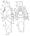
- the exterior of the illustrated housing 70 presents a narrow outer surface 76 extending from the distal end 78 of the pole 10 and a wide outer surface 80 spaced radially outward relative to the narrow surface 76.
- the wide surface 80 is spaced from the distal end 78, although the principles of the present invention are equally applicable to a wide surface that projects from the distal end as will be described.
- a thin (relative to the length of the pole 10) endmost section of the narrow surface 76 preferably extends completely around the housing 70, while the remaining section of the narrow surface 76 extends only partly around the housing 70.
- Such remaining section of the narrow surface 76 is preferably defined along an arc of approximately 260°.
- the narrow surface 76 is sized to be snugly received within the pole-receiving socket 32 of the tool handle 14, such that the surface 76 and internal wall 34 cooperatively restrict relative shifting of the pole 10 and tool 12 in directions perpendicular to the axis of the pole 10. Because the narrow surface 76 and wall 34 are cylindrical in shape in the illustrated embodiment, they do not prevent relative rotation between the pole 10 and tool 12. However, the housing 70 is provided with structure to nonetheless cooperate with the tool handle 14 in preventing relative rotation between the pole 10 and tool 12 as will be described.
- the wide surface 80 presents a generally frusto-conically shaped portion 80a and a boss portion 80b that rises out of and projects generally perpendicularly from the frusto-conically shaped portion.
- the portion 80a is generally smooth and widens as it approaches the distal end 78 of the pole 10.
- the preferred boss portion 80b has a shape that may generally be described as an elliptical fillet that terminates at a circular top edge.
- the top edge of the boss portion 80b presents an opening 82 in which the button 74 is received.
- the shape of the boss portion 80b creates a smooth continuous juncture with the frusto-conical portion 80a.
- the boss portion 80b is generally diametrically opposed from the 260° arcuate section of the narrow surface 76.
- a semicircular section 84 of the outer surface 80 projects toward the distal end 78 beyond part of the narrow surface 76.
- the semicircular section 84 cooperates with the 260° arcuate section of the narrow surface to extend around the housing 70, and the semicircular section 84 therefore extends along an arc of approximately 100°.
- a shoulder is presented around the housing 70.
- the shoulder comprises an endmost, circumferentially extending edge 86 and a pair of opposite, axially extending side edges 88 and 90.
- Rounded fillets 92 and 94 are each defined between the endmost edge 86 and a respective one of the side edges 88 and 90.
- the shoulder further includes a semicircular edge 96 that is parallel to the endmost edge 86 and spaced inwardly therefrom.
- the semicircular edge 96 extends between the side edges 88 and 90, with rounded fillets 98 and 100 each similarly being defined between the edge 96 and a respective one of the side edges 88 and 90. It is noted that in the preferred semicircular section 84 is cooperatively defined by the frusto-conical portion 80a and the boss portion 80b of the wide surface 80.
- the housing 70 is uniquely configured to matingly interfit with the tool handle 14.
- the semicircular section 84 of the outer surface 80 has a complementary geometry to that of the recess 36.
- the edges 86,88,90 and fillets 92,94 presented by the semicircular section 84 preferably abuttingly engage the corresponding edges 38,40,42 and fillets 44,46 of the recess 36, when the pole 10 and tool 12 are interconnected.
- the side edges 88 and 90 presented by the section 84 cooperate with the opposed edges 38 and 40 of the recess 36 to prevent or, at the very least, substantially restrict rotation between the handle 14 and housing 70.
- the section 84 may be described as a key received in a corresponding keyway (i.e., the recess 36) to prevent relative rotation between the pole 10 and tool 12.
- the preferred semicircular edge 96 and fillets 98,100 similarly engage the proximal end 26 and fillets 48,50 of the handle 14.
- the wide surface 80 of the housing 70 and the gripping surface 20 of the handle 14 are dimensioned to provide a smooth, continuous interface between the pole 10 and tool 12. That is to say, the wide surface 80 and the gripping surface 20 are flush and cooperatively give the impression of a single unitary outer face when the pole 10 and tool 12 are interconnected. It may alternatively be said that the smooth continuous face cooperatively presented by the gripping surface 20 and wide surface 80 is generally uninterrupted and without significant gaps at the juncture between the handle 14 and housing 70.
- the flush continuous relationship provided by the gripping surface 20 and wide surface 80 is primarily attributable to the equal thicknesses of the shoulder (defined between the narrow surface 76 and wide surface 80) and the handle wall along the recess 36 and proximal end 22 (defined between the gripping surface 20 and interior surface 34).
- the principles of the present invention are equally applicable to a shoulder and handle wall having different thicknesses.
- different shoulder and handle wall thicknesses may be desirable if the narrow surface of the housing is modified to be substantially undersized relative to the socket and thereby loosely received therein.
- the pole 10 and tool 12 are interconnected by axial movement toward one another.
- the pole connector 18 is inserted into the housing and cooperates with the locking mechanism 68 to automatically interlock the pole 10 and tool 12.
- the unique mating interfitting relationship of the handle 14 and housing 70 not only prevents relative rotation between the pole 10 and tool 12 but also provides a particularly attractive and comfortable junction therebetween. Again, this junction is uninterrupted, smooth and continuous.
- the extension pole 10 is therefore designed to provide a comfortable and attractive connection with the tool, while at the same time the extension pole 10 and tool 12 may not rotate relative to one another.
- the tool handle 14 illustrated in FIGS. 1-11 is provided with the pole connector 18 designed specifically for use with the locking mechanism 68.
- the extension pole 10 is provided with a tool handle having a pole connector that is not dedicated to use with the locking mechanism 68.
- FIG. 12 Such an alternative configuration is shown in FIG. 12, wherein the tool handle 200 is provided with a internally threaded connector 202. It will be appreciated that such a construction is disclosed in the incorporated '296 application.
- the illustrated connector 202 is adapted for use with "traditional" or "standard” extension poles used in the United States.
- a threaded adaptor 204 is provided so that the handle 200 may be used with the extension pole 10.
- the adaptor 204 includes an externally threaded end 206 received in the connector 202 and an opposite end 208 that is essentially identical to the locking portion 54 of the pole connector 18 illustrated in FIG. 11.
- the threaded end 206 of the adaptor 204 is fully received in the connector 202 (see FIG. 12)
- the positional relationships between the locking end 208 and tool handle 200 are virtually identical to those of the locking portion 54 and tool handle 14.
- the pole 10 similarly cooperates with the handle 200 to provide a smooth, continuous, comfortable and attractive junction between the tool 210 and pole 10.
- the present invention also contemplates various other constructional modifications and alterations.
- the configuration of the key section provided by the housing and the "keyway" provided by the handle may be varied and still perform the same function.
- One suitable variation involves altering the size of the key section (e.g., the key section may extend to a lesser or greater degree around the housing). It may also be possible to vary the shape of the key section (e.g., the key section may have sharp comers, be triangular in shape, etc.).
- Another alternative embodiment involves the use of a plurality of key sections. The key sections resemble a series of teeth that are received in a like number of correspondingly defined tool handle recesses.
Landscapes
- Engineering & Computer Science (AREA)
- Mechanical Engineering (AREA)
- Coating Apparatus (AREA)
- Mutual Connection Of Rods And Tubes (AREA)
- Details Of Spanners, Wrenches, And Screw Drivers And Accessories (AREA)
- Fishing Rods (AREA)
- Earth Drilling (AREA)
- Surgical Instruments (AREA)
Applications Claiming Priority (2)
| Application Number | Priority Date | Filing Date | Title |
|---|---|---|---|
| US632513 | 2000-08-04 | ||
| US09/632,513 US6532630B1 (en) | 2000-08-04 | 2000-08-04 | Matingly interfitted tool handle and extension for preventing relative rotation |
Publications (3)
| Publication Number | Publication Date |
|---|---|
| EP1177863A2 true EP1177863A2 (fr) | 2002-02-06 |
| EP1177863A3 EP1177863A3 (fr) | 2002-10-30 |
| EP1177863B1 EP1177863B1 (fr) | 2008-03-19 |
Family
ID=24535805
Family Applications (1)
| Application Number | Title | Priority Date | Filing Date |
|---|---|---|---|
| EP01115628A Expired - Lifetime EP1177863B1 (fr) | 2000-08-04 | 2001-07-03 | Rallonge adaptable sur un manche d'outil et pourvu d'un méchanisme pour empêcher sa rotation relative |
Country Status (6)
| Country | Link |
|---|---|
| US (2) | US6532630B1 (fr) |
| EP (1) | EP1177863B1 (fr) |
| AT (1) | ATE389515T1 (fr) |
| CA (1) | CA2353287C (fr) |
| DE (1) | DE60133247D1 (fr) |
| MX (1) | MXPA01007849A (fr) |
Cited By (7)
| Publication number | Priority date | Publication date | Assignee | Title |
|---|---|---|---|---|
| USD528729S1 (en) | 2005-05-10 | 2006-09-19 | Rubbermaid Commerical Products Llc | Cart |
| USD529294S1 (en) | 2005-01-31 | 2006-10-03 | Rubbermaid Commercial Products Llc | Universal joint |
| USD533356S1 (en) | 2005-01-31 | 2006-12-12 | Rubbermaid Commercial Products Llc | Universal joint |
| USD547017S1 (en) | 2005-05-10 | 2007-07-17 | Rubbermaid Commercial Products Llc | Mop handle |
| USD548913S1 (en) | 2005-05-10 | 2007-08-14 | Rubbermaid Commercial Products Llc | Mop bucket and wringer |
| USD549414S1 (en) | 2005-01-31 | 2007-08-21 | Rubbermaid Commercial Products Llc | Mop frame |
| USD549912S1 (en) | 2007-01-12 | 2007-08-28 | Rubbermaid Commercial Products Llc | Mop |
Families Citing this family (27)
| Publication number | Priority date | Publication date | Assignee | Title |
|---|---|---|---|---|
| US20040103761A1 (en) * | 2002-10-15 | 2004-06-03 | Pillow Thomas M. | Fixed angle extension for a tool |
| US6889917B2 (en) * | 2003-03-10 | 2005-05-10 | S.C. Johnson & Son, Inc. | Cleaning device with universal motion quick disconnect head |
| MXPA06012795A (es) * | 2004-05-05 | 2007-02-15 | Rubbermaid Commercial Products | Almohadillas de trapeador codificadas por color y metodo para codificar por color las mismas. |
| WO2005107565A1 (fr) * | 2004-05-05 | 2005-11-17 | Rubbermaid Commercial Products Llc | Lavettes pour balais, a codage couleur, et procede de codage couleur associe |
| US7237305B2 (en) * | 2004-06-02 | 2007-07-03 | Specialty Products Of Greenwood, Missouri, Inc. | Extension pole with tool lock and retraction dampener |
| USD519820S1 (en) | 2004-06-02 | 2006-05-02 | Specialty Products Of Greenwood, Missouri, Inc. | Extension pole |
| US20050279193A1 (en) * | 2004-06-17 | 2005-12-22 | Darby Lioyd C | Method and apparatus for facilitating removal and attachment of automobile tires |
| USD559490S1 (en) * | 2004-07-13 | 2008-01-08 | Hayco Manufacturing Limited | Handle for cleaning implement |
| DE102004047162A1 (de) * | 2004-09-29 | 2006-04-06 | Carl Freudenberg Kg | Stiel für ein Reinigungsgerät |
| US20060147256A1 (en) * | 2004-12-30 | 2006-07-06 | Specialty Products Of Greenwood, Missouri, Inc. | Selectively rotatable tool connector |
| USD598257S1 (en) | 2005-02-11 | 2009-08-18 | Darby Lloyd C | Lug wrench extender |
| USD538133S1 (en) | 2005-02-23 | 2007-03-13 | Specialty Products Of Greenwood, Missouri, Inc. | Lock mechanism housing of a telescopic extension pole |
| US20060230581A1 (en) * | 2005-04-15 | 2006-10-19 | Specialty Products Of Greenwood, Missouri, Inc. | Locking mechanism for an extension pole |
| US7716790B2 (en) * | 2005-12-22 | 2010-05-18 | Robert D. Newman, Jr. | On-the-go adjustable extension pole providing hands-free tool connection and disconnection |
| US7681285B2 (en) * | 2006-09-18 | 2010-03-23 | Natura Innovation Ltd. | Detachable handle mounting structure |
| USD677031S1 (en) | 2010-04-13 | 2013-02-26 | Specialty Products Of Greenwood, Missouri, Inc. | Applicator head |
| USD663501S1 (en) | 2010-04-13 | 2012-07-10 | Specialty Products Of Greenwood, Missouri, Inc. | Applicator with individual pad support fingers |
| USD668827S1 (en) | 2010-04-13 | 2012-10-09 | Specialty Products Of Greenwood, Missouri, Inc. | Basic applicator head |
| USD674567S1 (en) | 2010-04-13 | 2013-01-15 | Specialty Products Of Greenwood, Missouri, Inc. | Applicator head |
| USD647308S1 (en) | 2010-04-13 | 2011-10-25 | Specialty Products Of Greenwood, Missouri, Inc. | Flow-through brush head |
| USD664418S1 (en) * | 2011-04-01 | 2012-07-31 | Garant Gp | Push button |
| US9764458B1 (en) | 2012-09-21 | 2017-09-19 | Eric Resh | Telepole, and related methods |
| US11090798B2 (en) | 2011-09-22 | 2021-08-17 | Resh, Inc. | Telepole apparatus and related methods |
| USD752304S1 (en) * | 2015-02-16 | 2016-03-22 | Garant Gp | Push button |
| EP3515669B1 (fr) | 2016-11-18 | 2022-01-05 | Specialty Products of Greenwood, Missouri, Inc. | Raccordement d'outil à réglage angulaire à raccord fileté et raccord de type pince |
| CA3091432C (fr) | 2018-02-19 | 2022-12-13 | Springfield Innovation Group LLC | Poignee pliable pour un outil |
| USD893977S1 (en) | 2019-02-19 | 2020-08-25 | Springfield Innovation Group LLC | Hinged joint for a tool handle |
Citations (2)
| Publication number | Priority date | Publication date | Assignee | Title |
|---|---|---|---|---|
| US5220707A (en) | 1991-11-06 | 1993-06-22 | Mr. Longarm, Inc. | Tool reach extender with locking assembly |
| US5682641A (en) | 1995-06-29 | 1997-11-04 | Robert D. Newman, Sr. | Tool handle with locking assembly |
Family Cites Families (20)
| Publication number | Priority date | Publication date | Assignee | Title |
|---|---|---|---|---|
| US2902592A (en) * | 1957-07-05 | 1959-09-01 | Rex Cole Inc | Portable lamp |
| US3462202A (en) * | 1968-01-10 | 1969-08-19 | Bestt Rollr Inc | Handle for paint roller |
| US3596946A (en) * | 1970-03-09 | 1971-08-03 | Wooster Brush Co The | Cam lock for telescopic members |
| US3745624A (en) * | 1972-01-27 | 1973-07-17 | R Newman | Extensible paint roller frame |
| US4076437A (en) * | 1977-03-04 | 1978-02-28 | H & G Industries, Inc. | Positive cam lock for extension pole |
| US4325157A (en) * | 1979-08-09 | 1982-04-20 | E Z Painter Corporation | Extension handle |
| DE3046286A1 (de) * | 1980-12-09 | 1982-07-08 | Vorwerk & Co Interholding Gmbh, 5600 Wuppertal | Rastung fuer teleskopierbare fuehrungsstiele |
| US4524484A (en) * | 1983-06-15 | 1985-06-25 | Swiss-Tex, Incorporated | Extension handle having cooperating male and female locking sleeves |
| US4605378A (en) * | 1984-12-20 | 1986-08-12 | Hamilton Don A | Breakdown boat paddle with variable configuration |
| US4659125A (en) * | 1985-05-23 | 1987-04-21 | Ching Chuan | Handle rod structure of golf retriever |
| DE3628004A1 (de) * | 1986-08-18 | 1988-02-25 | Langenstein Feld Garten | Arbeitsgeraet, wie gartengeraet, putzgeraet oder dergl. |
| USD315286S (en) * | 1988-01-29 | 1991-03-12 | The Wooster Brush Company | Lock for an extension pole |
| US5288161A (en) * | 1992-02-14 | 1994-02-22 | The Wooster Brush Company | Quick release lock mechanisms |
| US5507204A (en) * | 1995-01-31 | 1996-04-16 | Howe Furniture Corporation | Crank Handle |
| US5579558A (en) | 1995-06-29 | 1996-12-03 | Robert D. Newman, Sr. | Tool handle with locking assembly |
| US5983455A (en) * | 1997-06-19 | 1999-11-16 | Newell Operating Company | Multi-faceted extension pole |
| US6231265B1 (en) * | 1999-02-26 | 2001-05-15 | Schlumberger Technology Corporation | Self-aligning subsea latch mechanism |
| US6254305B1 (en) * | 1999-07-14 | 2001-07-03 | Curtis E. Taylor | Locking mechanism for telescopically adjustable extension pole |
| USD447874S1 (en) * | 2000-01-29 | 2001-09-18 | Robert D. Newman | Tool handle |
| USD452777S1 (en) * | 2000-08-04 | 2002-01-08 | Robert D. Newman | Extension pole |
-
2000
- 2000-08-04 US US09/632,513 patent/US6532630B1/en not_active Expired - Lifetime
-
2001
- 2001-07-03 EP EP01115628A patent/EP1177863B1/fr not_active Expired - Lifetime
- 2001-07-03 DE DE60133247T patent/DE60133247D1/de not_active Expired - Lifetime
- 2001-07-03 AT AT01115628T patent/ATE389515T1/de not_active IP Right Cessation
- 2001-07-19 CA CA002353287A patent/CA2353287C/fr not_active Expired - Lifetime
- 2001-08-02 MX MXPA01007849A patent/MXPA01007849A/es active IP Right Grant
- 2001-10-31 US US09/682,918 patent/US6530124B2/en not_active Expired - Fee Related
Patent Citations (2)
| Publication number | Priority date | Publication date | Assignee | Title |
|---|---|---|---|---|
| US5220707A (en) | 1991-11-06 | 1993-06-22 | Mr. Longarm, Inc. | Tool reach extender with locking assembly |
| US5682641A (en) | 1995-06-29 | 1997-11-04 | Robert D. Newman, Sr. | Tool handle with locking assembly |
Cited By (7)
| Publication number | Priority date | Publication date | Assignee | Title |
|---|---|---|---|---|
| USD529294S1 (en) | 2005-01-31 | 2006-10-03 | Rubbermaid Commercial Products Llc | Universal joint |
| USD533356S1 (en) | 2005-01-31 | 2006-12-12 | Rubbermaid Commercial Products Llc | Universal joint |
| USD549414S1 (en) | 2005-01-31 | 2007-08-21 | Rubbermaid Commercial Products Llc | Mop frame |
| USD528729S1 (en) | 2005-05-10 | 2006-09-19 | Rubbermaid Commerical Products Llc | Cart |
| USD547017S1 (en) | 2005-05-10 | 2007-07-17 | Rubbermaid Commercial Products Llc | Mop handle |
| USD548913S1 (en) | 2005-05-10 | 2007-08-14 | Rubbermaid Commercial Products Llc | Mop bucket and wringer |
| USD549912S1 (en) | 2007-01-12 | 2007-08-28 | Rubbermaid Commercial Products Llc | Mop |
Also Published As
| Publication number | Publication date |
|---|---|
| ATE389515T1 (de) | 2008-04-15 |
| US20020021013A1 (en) | 2002-02-21 |
| DE60133247D1 (de) | 2008-04-30 |
| EP1177863A3 (fr) | 2002-10-30 |
| EP1177863B1 (fr) | 2008-03-19 |
| CA2353287A1 (fr) | 2002-02-04 |
| US6530124B2 (en) | 2003-03-11 |
| MXPA01007849A (es) | 2004-05-31 |
| US6532630B1 (en) | 2003-03-18 |
| CA2353287C (fr) | 2005-10-18 |
Similar Documents
| Publication | Publication Date | Title |
|---|---|---|
| US6532630B1 (en) | Matingly interfitted tool handle and extension for preventing relative rotation | |
| US6779235B2 (en) | Universal tool handle configured for various extension pole connectors | |
| US7036401B2 (en) | Extendable spline-drive socket system | |
| US5768960A (en) | Locking swivel head ratchet wrench | |
| US6543959B1 (en) | Two-way quick connector | |
| US5940933A (en) | Telescopic handle for a mop | |
| CA2306006C (fr) | Ensemble de lames a changement rapide, pour tondeuse a coupe rotative | |
| US20030210963A1 (en) | Rotary tool and cutting part comprised in the tool | |
| US20050011318A1 (en) | Connecting compensating device of multiangular wrench socket | |
| US7337697B2 (en) | Depth stop device | |
| US9403216B2 (en) | First coupling part and tool coupling | |
| JPH11500212A (ja) | 切離し可能なカップリングおよび切離し用の工具 | |
| EP1712297A1 (fr) | Mecanisme de verrouillage pour tige rallonge | |
| US5210898A (en) | Wooden broom assembly and adapter means therefor | |
| EP1259358B1 (fr) | Raccord de manche a balai ou analogue | |
| US5379535A (en) | Replaceable excavating tooth assembly | |
| US6405396B1 (en) | Screwdriver assembly with an extendable rod | |
| EP1457291B1 (fr) | Accouplement outil rapporté /tige d'entraînement | |
| US20110206452A1 (en) | Locking coupler for a drive shaft | |
| US3640641A (en) | Adapter for working implements | |
| CN2355850Y (zh) | 一种可偏摆角度的套筒 | |
| CN211433166U (zh) | 螺旋刀片 | |
| EP2325537A2 (fr) | Raccord de tuyau flexible | |
| JPH08270168A (ja) | 手すり連結装置 | |
| JPH0653065U (ja) | ドライバービット保持機構 |
Legal Events
| Date | Code | Title | Description |
|---|---|---|---|
| PUAI | Public reference made under article 153(3) epc to a published international application that has entered the european phase |
Free format text: ORIGINAL CODE: 0009012 |
|
| AK | Designated contracting states |
Kind code of ref document: A2 Designated state(s): AT BE CH CY DE DK ES FI FR GB GR IE IT LI LU MC NL PT SE TR |
|
| AX | Request for extension of the european patent |
Free format text: AL;LT;LV;MK;RO;SI |
|
| RAP1 | Party data changed (applicant data changed or rights of an application transferred) |
Owner name: NEWMAN, ROBERT D. Owner name: SPECIALTY PRODUCTS OF GREENWOOD, MISSOURI, INC. |
|
| PUAL | Search report despatched |
Free format text: ORIGINAL CODE: 0009013 |
|
| RIC1 | Information provided on ipc code assigned before grant |
Free format text: 7B 25G 1/04 A, 7B 25G 3/18 B, 7F 16B 7/00 B, 7B 05C 17/02 B |
|
| AK | Designated contracting states |
Kind code of ref document: A3 Designated state(s): AT BE CH CY DE DK ES FI FR GB GR IE IT LI LU MC NL PT SE TR |
|
| AX | Request for extension of the european patent |
Free format text: AL;LT;LV;MK;RO;SI |
|
| 17P | Request for examination filed |
Effective date: 20030203 |
|
| AKX | Designation fees paid |
Designated state(s): AT BE CH CY DE DK ES FI FR GB GR IE IT LI LU MC NL PT SE TR |
|
| GRAP | Despatch of communication of intention to grant a patent |
Free format text: ORIGINAL CODE: EPIDOSNIGR1 |
|
| GRAS | Grant fee paid |
Free format text: ORIGINAL CODE: EPIDOSNIGR3 |
|
| GRAA | (expected) grant |
Free format text: ORIGINAL CODE: 0009210 |
|
| AK | Designated contracting states |
Kind code of ref document: B1 Designated state(s): AT BE CH CY DE DK ES FI FR GB GR IE IT LI LU MC NL PT SE TR |
|
| REG | Reference to a national code |
Ref country code: GB Ref legal event code: FG4D |
|
| REG | Reference to a national code |
Ref country code: CH Ref legal event code: EP |
|
| REF | Corresponds to: |
Ref document number: 60133247 Country of ref document: DE Date of ref document: 20080430 Kind code of ref document: P |
|
| REG | Reference to a national code |
Ref country code: IE Ref legal event code: FG4D |
|
| PG25 | Lapsed in a contracting state [announced via postgrant information from national office to epo] |
Ref country code: FI Free format text: LAPSE BECAUSE OF FAILURE TO SUBMIT A TRANSLATION OF THE DESCRIPTION OR TO PAY THE FEE WITHIN THE PRESCRIBED TIME-LIMIT Effective date: 20080319 |
|
| PG25 | Lapsed in a contracting state [announced via postgrant information from national office to epo] |
Ref country code: AT Free format text: LAPSE BECAUSE OF FAILURE TO SUBMIT A TRANSLATION OF THE DESCRIPTION OR TO PAY THE FEE WITHIN THE PRESCRIBED TIME-LIMIT Effective date: 20080319 |
|
| NLV1 | Nl: lapsed or annulled due to failure to fulfill the requirements of art. 29p and 29m of the patents act | ||
| PG25 | Lapsed in a contracting state [announced via postgrant information from national office to epo] |
Ref country code: BE Free format text: LAPSE BECAUSE OF FAILURE TO SUBMIT A TRANSLATION OF THE DESCRIPTION OR TO PAY THE FEE WITHIN THE PRESCRIBED TIME-LIMIT Effective date: 20080319 |
|
| PG25 | Lapsed in a contracting state [announced via postgrant information from national office to epo] |
Ref country code: ES Free format text: LAPSE BECAUSE OF FAILURE TO SUBMIT A TRANSLATION OF THE DESCRIPTION OR TO PAY THE FEE WITHIN THE PRESCRIBED TIME-LIMIT Effective date: 20080630 Ref country code: PT Free format text: LAPSE BECAUSE OF FAILURE TO SUBMIT A TRANSLATION OF THE DESCRIPTION OR TO PAY THE FEE WITHIN THE PRESCRIBED TIME-LIMIT Effective date: 20080826 Ref country code: SE Free format text: LAPSE BECAUSE OF FAILURE TO SUBMIT A TRANSLATION OF THE DESCRIPTION OR TO PAY THE FEE WITHIN THE PRESCRIBED TIME-LIMIT Effective date: 20080619 |
|
| PG25 | Lapsed in a contracting state [announced via postgrant information from national office to epo] |
Ref country code: NL Free format text: LAPSE BECAUSE OF FAILURE TO SUBMIT A TRANSLATION OF THE DESCRIPTION OR TO PAY THE FEE WITHIN THE PRESCRIBED TIME-LIMIT Effective date: 20080319 |
|
| EN | Fr: translation not filed | ||
| PLBE | No opposition filed within time limit |
Free format text: ORIGINAL CODE: 0009261 |
|
| STAA | Information on the status of an ep patent application or granted ep patent |
Free format text: STATUS: NO OPPOSITION FILED WITHIN TIME LIMIT |
|
| PG25 | Lapsed in a contracting state [announced via postgrant information from national office to epo] |
Ref country code: DK Free format text: LAPSE BECAUSE OF FAILURE TO SUBMIT A TRANSLATION OF THE DESCRIPTION OR TO PAY THE FEE WITHIN THE PRESCRIBED TIME-LIMIT Effective date: 20080319 Ref country code: DE Free format text: LAPSE BECAUSE OF FAILURE TO SUBMIT A TRANSLATION OF THE DESCRIPTION OR TO PAY THE FEE WITHIN THE PRESCRIBED TIME-LIMIT Effective date: 20080620 |
|
| 26N | No opposition filed |
Effective date: 20081222 |
|
| REG | Reference to a national code |
Ref country code: CH Ref legal event code: PL |
|
| PG25 | Lapsed in a contracting state [announced via postgrant information from national office to epo] |
Ref country code: MC Free format text: LAPSE BECAUSE OF NON-PAYMENT OF DUE FEES Effective date: 20080731 |
|
| PG25 | Lapsed in a contracting state [announced via postgrant information from national office to epo] |
Ref country code: LI Free format text: LAPSE BECAUSE OF NON-PAYMENT OF DUE FEES Effective date: 20080731 Ref country code: CH Free format text: LAPSE BECAUSE OF NON-PAYMENT OF DUE FEES Effective date: 20080731 |
|
| PG25 | Lapsed in a contracting state [announced via postgrant information from national office to epo] |
Ref country code: IE Free format text: LAPSE BECAUSE OF NON-PAYMENT OF DUE FEES Effective date: 20080703 |
|
| PG25 | Lapsed in a contracting state [announced via postgrant information from national office to epo] |
Ref country code: IT Free format text: LAPSE BECAUSE OF FAILURE TO SUBMIT A TRANSLATION OF THE DESCRIPTION OR TO PAY THE FEE WITHIN THE PRESCRIBED TIME-LIMIT Effective date: 20080319 |
|
| PG25 | Lapsed in a contracting state [announced via postgrant information from national office to epo] |
Ref country code: CY Free format text: LAPSE BECAUSE OF FAILURE TO SUBMIT A TRANSLATION OF THE DESCRIPTION OR TO PAY THE FEE WITHIN THE PRESCRIBED TIME-LIMIT Effective date: 20080319 |
|
| PG25 | Lapsed in a contracting state [announced via postgrant information from national office to epo] |
Ref country code: LU Free format text: LAPSE BECAUSE OF NON-PAYMENT OF DUE FEES Effective date: 20080703 |
|
| PG25 | Lapsed in a contracting state [announced via postgrant information from national office to epo] |
Ref country code: TR Free format text: LAPSE BECAUSE OF FAILURE TO SUBMIT A TRANSLATION OF THE DESCRIPTION OR TO PAY THE FEE WITHIN THE PRESCRIBED TIME-LIMIT Effective date: 20080319 |
|
| PG25 | Lapsed in a contracting state [announced via postgrant information from national office to epo] |
Ref country code: GR Free format text: LAPSE BECAUSE OF FAILURE TO SUBMIT A TRANSLATION OF THE DESCRIPTION OR TO PAY THE FEE WITHIN THE PRESCRIBED TIME-LIMIT Effective date: 20080620 |
|
| PG25 | Lapsed in a contracting state [announced via postgrant information from national office to epo] |
Ref country code: FR Free format text: LAPSE BECAUSE OF FAILURE TO SUBMIT A TRANSLATION OF THE DESCRIPTION OR TO PAY THE FEE WITHIN THE PRESCRIBED TIME-LIMIT Effective date: 20090109 |
|
| PGFP | Annual fee paid to national office [announced via postgrant information from national office to epo] |
Ref country code: GB Payment date: 20200727 Year of fee payment: 20 |
|
| REG | Reference to a national code |
Ref country code: GB Ref legal event code: PE20 Expiry date: 20210702 |
|
| PG25 | Lapsed in a contracting state [announced via postgrant information from national office to epo] |
Ref country code: GB Free format text: LAPSE BECAUSE OF EXPIRATION OF PROTECTION Effective date: 20210702 |