EP1178005B1 - Dispositif pour commande manuelle et guidage d'un appareil de manipulation - Google Patents
Dispositif pour commande manuelle et guidage d'un appareil de manipulation Download PDFInfo
- Publication number
- EP1178005B1 EP1178005B1 EP01250240A EP01250240A EP1178005B1 EP 1178005 B1 EP1178005 B1 EP 1178005B1 EP 01250240 A EP01250240 A EP 01250240A EP 01250240 A EP01250240 A EP 01250240A EP 1178005 B1 EP1178005 B1 EP 1178005B1
- Authority
- EP
- European Patent Office
- Prior art keywords
- elements
- housing
- handle
- crossmember
- guide frame
- Prior art date
- Legal status (The legal status is an assumption and is not a legal conclusion. Google has not performed a legal analysis and makes no representation as to the accuracy of the status listed.)
- Expired - Lifetime
Links
- 238000006073 displacement reaction Methods 0.000 claims abstract description 5
- 210000003813 thumb Anatomy 0.000 claims description 5
- 239000000243 solution Substances 0.000 description 6
- 239000000725 suspension Substances 0.000 description 3
- 230000006978 adaptation Effects 0.000 description 2
- 229910052782 aluminium Inorganic materials 0.000 description 1
- XAGFODPZIPBFFR-UHFFFAOYSA-N aluminium Chemical compound [Al] XAGFODPZIPBFFR-UHFFFAOYSA-N 0.000 description 1
- 230000001419 dependent effect Effects 0.000 description 1
- 238000012423 maintenance Methods 0.000 description 1
- 229910052751 metal Inorganic materials 0.000 description 1
- 239000002184 metal Substances 0.000 description 1
Images


Classifications
-
- B—PERFORMING OPERATIONS; TRANSPORTING
- B66—HOISTING; LIFTING; HAULING
- B66C—CRANES; LOAD-ENGAGING ELEMENTS OR DEVICES FOR CRANES, CAPSTANS, WINCHES, OR TACKLES
- B66C13/00—Other constructional features or details
- B66C13/52—Details of compartments for driving engines or motors or of operator's stands or cabins
- B66C13/54—Operator's stands or cabins
- B66C13/56—Arrangements of handles or pedals
-
- B—PERFORMING OPERATIONS; TRANSPORTING
- B66—HOISTING; LIFTING; HAULING
- B66D—CAPSTANS; WINCHES; TACKLES, e.g. PULLEY BLOCKS; HOISTS
- B66D3/00—Portable or mobile lifting or hauling appliances
- B66D3/18—Power-operated hoists
-
- H—ELECTRICITY
- H01—ELECTRIC ELEMENTS
- H01H—ELECTRIC SWITCHES; RELAYS; SELECTORS; EMERGENCY PROTECTIVE DEVICES
- H01H9/00—Details of switching devices, not covered by groups H01H1/00 - H01H7/00
- H01H9/02—Bases, casings, or covers
- H01H9/06—Casing of switch constituted by a handle serving a purpose other than the actuation of the switch, e.g. by the handle of a vacuum cleaner
- H01H2009/068—Casing of switch constituted by a handle serving a purpose other than the actuation of the switch, e.g. by the handle of a vacuum cleaner with switches mounted on a handlebar, e.g. for motorcycles, fork lift trucks, etc.
-
- H—ELECTRICITY
- H01—ELECTRIC ELEMENTS
- H01H—ELECTRIC SWITCHES; RELAYS; SELECTORS; EMERGENCY PROTECTIVE DEVICES
- H01H2300/00—Orthogonal indexing scheme relating to electric switches, relays, selectors or emergency protective devices covered by H01H
- H01H2300/026—Application dead man switch: power must be interrupted on release of operating member
Definitions
- the invention relates to a device for manual control and manual guidance a handling device that a movement device, in particular a Lifting device, according to the preamble of claims 1 and 7.
- EP 0 586 029 B1 describes a device for manual and manual control Management of a hoist with a lifting device known.
- the hoist instructs lifting device that can be raised and lowered by the lifting device, at its free end a device for controlling and guiding a load suspension device is arranged is.
- the load handler is attached directly to the device.
- the Device has a housing on which a horizontal handle is formed, which can be gripped by the hand of an operator. That way it will Load handler guided by the operator.
- Switch plunger arranged as switching elements with the control of the lifting device are electrically connected and can be operated from the outside by means of a rocker switch.
- the handle is arranged with respect to the rocker switch so that it is one of the thumb the hand grasping the handle is easily accessible.
- the object of the invention is to provide a device for manual control and manual Guidance of a movement device, in particular a lifting device, Proposing handling device to propose, which with little effort various handling devices as well as the individual needs of respective operators and to the ergonomic conditions as well is particularly adaptable to different lifting heights.
- a first solution provides that one at the two free ends on the housing detachably fastened substantially horizontal first cross member transversely to this upwards and / or downwards each detachable with the associated end connected grip element is provided, the position of at least one of the Handle elements in relation to at least one of the switching and / or touch elements Longitudinal displacement of the cross member adjustable before it is fixed on the housing and that the two handle elements together with the cross member Form a leadership framework that is designed to adapt to specific needs Handle elements and crossbeams of different lengths in the manner of a modular system is mountable. The adaptation to different requirements is therefore ensures that the unit is made up of elements of different lengths Building kit is mountable.
- the elements are essentially grip elements and Cross member, wherein at least one cross member releasably attached to the housing of the unit is that carries a handle element at its free ends.
- the length of one unit handle elements and cross members used first determine the basic size of the Unit.
- at least the position of a grip element is relative to the Switching and / or sensing elements adjustable, namely by longitudinal displacement of the Cross member before attaching it to the housing.
- the unit is in the form of a handlebar attached to an elongated housing with two Grips, like a bicycle handlebar.
- the housing from one to the Ends and formed on one long side open hollow profile and the open the Back of the housing forming longitudinal side can be closed like a lid.
- the unit can be easily adapted to the size of an operator achieve with little effort that at least one belonging to the housing longitudinally and also laterally displaceable as well as lockable element housing unit Type of satellite is provided, some or all of the switching and / or sensing elements having.
- the handle elements are a large distance must have from each other.
- the first cross member on two spaced housings arranged parallel to each other is releasably attached, the housing in turn last with the handling device are connected.
- grip elements are the corresponding switching and / or Easily accessible touch elements from both thumbs
- the stability of the unit increases if one free end each of the two handle elements one of the two housings is releasably attached.
- a second solution of the unit with two spaced parallel housings provides that at the two free ends of a substantially horizontal first Cross member extending transversely to this up and / or down one with each associated end connected grip element is provided and the two free Ends of the grip elements with one another by means of a second cross member are connected that the parallel cross-member and Pair of handle elements form a closed flat guide frame that for Detachable connection of the cross member and the grip elements with connecting elements at least one projection each are provided on the assembled guide frame aligned parallel to each other, that at least two at a distance housings arranged parallel to one another and corresponding to the projections
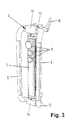
- Fig. 1 shows a by means of a movement device, not shown extendable vertical mast 1 of a handling device, at the lower end of which Load handling device 2 is arranged in the form of a gripper.
- a device 3 for manual control and manual guidance by an operator 4 whose hand is also shown vertically aligned rod-shaped handle element 5 of the device 3 that grips out a piece of pipe is formed.
- Parallel to this grip element 5 is on the device 3 a second handle element 5 is provided, which together with two also Existing cross members 6 form a stable guide frame 6a, which is releasably attached to a housing 7 of the unit 3 with the aid of the cross member 6.
- the handle elements 5 and the cross members 6 are detachable at the ends connected.
- the guide frame 6a is ergonomic in size Adjusted operator so that the guide frame 6a to the Handle elements 5 can comfortably include, the actuating elements 12 of the 1 upper right element housing unit 9 from the thumb of the Operator 4 are easily accessible without the handle element 5 have to let go.
- the ends of the Handle elements 5 and the cross member 6 each releasable via connecting elements 13 connected with each other.
- These consist of bent pipe pieces in the ends one end of a cross member 6 and one end of a handle element 5 can be inserted is.
- the detachable connection is made, for example, by means of a not shown Locking mechanism or by means of dowel pins.
- the connecting elements 13 are like this bent that the two handle elements 5 and the two cross members 6 each in lie on a common plane, both planes running parallel to one another. In this way, the grip elements 5 are in relation to the transverse elements 6 Predetermined dimension closer to the operator 4 arranged, which more space for Element housing units 9 leaves.
- a holding element 14 For fastening the guide frame 6a to the housing 7 is a holding element 14 provided with a horizontal cylindrical through opening through which the associated cross member 6 is guided longitudinally. This enables one horizontal displacement of the entire guide frame 6a and thus the Handle elements 5 with respect to the actuating elements 11, 12. On the embodiment the cross member 6 are then releasably by clamping with the Holding elements 14 connected.
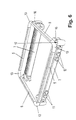
- FIG. 2 and 3 show two further closed versions of the guide frame 6a, the embodiment according to FIG. 2 only a single pair Element housing units 9 and the guide frame 6a in Fig. 3 none Has element housing unit 9.
- Fig. 4 shows a guide frame 6a in the manner of a bicycle handlebar with only one single cross member 6 and two downwardly extending grip elements 5.
- the handle elements 5 can also be up and down or only be arranged on the cross member 7 extending upwards.
- the guide frame in Fig. 5 consists of a cross member 6, on the two housings 7 are arranged parallel to each other at a distance.
- the attachment to the cross member 6 takes place here also by means of holding elements 14.
- Both housings 7 are on the vertical mast 1 attached, which is to be provided with a corresponding mounting plate.
- the handle elements 5 with their cross member 6 opposite ends also attached to the associated housing 7.
- the attachment is also carried out by means of the holding elements 14 and a cross member 15 each are in turn connected to the grip elements 5 via connecting elements 13.
- the Guide frame 6a, the two handle elements 5 and the two cross members 6 in one single common level.
- the connecting elements 13 are like this designed that they can be detachably connected to the two housings 7.
- These projections 16 are corresponding Cylinder openings 17 of the housing 7 can be used.
- the locking can be done by means of a Screw and the like.
- handle elements 5 and the cross member 6 and the housing 7 belong to a kit, d. H. they are available in different lengths.
- To this Modules also include the connecting elements 13 and the holding elements 14 which in the exemplary embodiment only for an outer diameter of the grip elements 5 and Cross member 6 are provided.
- Handle elements 5 and cross member have different outer diameters.
- the housing 7 consists of a piece of a hollow profile, which is on one long side is open.
- the open long side forms the back of the housing 7 and is by means of a sheet metal strip can be closed like a lid. Closing the top and lower end of the housing takes place by means of the holding elements 14, which for this purpose in the front housing openings can be inserted and then by means of screws are attachable.
- the hollow profile piece can for example be made of extruded Aluminum.
- 1-6 also show, it is possible to the housing 7 and thus the To fix the guide frame 6a on the holding elements 14 on the vertical mast 1, and although over a horizontal pivot axis about which the guide frame 6a is pivotable.
- the lower one is in the exemplary embodiment Housing attachment pivotable about a horizontal axis, which in use a clamping element 18 for the upper attachment a simple folding down Allows guide frame 6a.
- electrical cables and pneumatic lines can be easily replaced, renewed and connected, so that the assembly and maintenance considerably simplified.
- the cables can also go through the cross beams Satellite guided.
Landscapes
- Engineering & Computer Science (AREA)
- Mechanical Engineering (AREA)
- Load-Engaging Elements For Cranes (AREA)
- Manipulator (AREA)
- Details Of Rigid Or Semi-Rigid Containers (AREA)
- Handcart (AREA)
- Forklifts And Lifting Vehicles (AREA)
- Push-Button Switches (AREA)
- Prostheses (AREA)
- Electrical Discharge Machining, Electrochemical Machining, And Combined Machining (AREA)
- User Interface Of Digital Computer (AREA)
Claims (7)
- Dispositif de commande manuelle et de guidage manuel d'un appareil de manipulation, en particulier d'un engin de levage qui comporte un dispositif de déplacement, en particulier un dispositif de levage, lequel dispositif comporte
un boítier (7) qui peut être fixé à l'appareil de manipulation ou bien à un moyen de support de l'appareil de manipulation et dans lequel sont disposés des éléments de commutation et/ou de manipulation reliés à une commande en vue de commander le dispositif de déplacement au moyen d'éléments de commande (11, 12) actionnables de l'extérieur, et
au moins un élément de préhension (5) disposé au niveau du boítier et pouvant être saisi par la main d'un opérateur, l'élément de préhension permettant au pouce d'accéder à l'un au moins des éléments de commande (11, 12),
caractérisé en ce qu'un élément de préhension (5) est prévu au niveau des deux extrémités d'une première barre transversale (6) sensiblement horizontale fixée de façon amovible au boítier (7), ledit élément de préhension s'étendant vers le haut et/ou vers le bas transversalement à ladite barre horizontale et étant relié de façon amovible à l'extrémité associée, la position de l'un au moins des éléments de préhension (5) étant réglable par rapport à l'un au moins des éléments de commutation et/ou de manipulation en déplaçant la barre transversale (6) longitudinalement avant de la fixer au boítier (7),
et en ce que les deux éléments de préhension (5) forment conjointement avec la barre transversale (6) un cadre de guidage (6a) qui peut être monté de façon modulaire en vue de l'adaptation aux exigences respectives dues à des éléments de préhension (5) et des barres transversales (6) de longueurs différentes. - Dispositif selon la revendication 1, caractérisé en ce que le boítier (7) est formé d'un profilé creux ouvert aux extrémités et sur un côté longitudinal et le côté longitudinal ouvert formant le dos du boítier (7) peut être fermé à la manière d'un couvercle.
- Dispositif selon l'une des revendications 1 ou 2, caractérisé en ce qu'il est prévu à la manière d'un satellite au moins une unité (9) de boítier d'élément associée au boítier (7) qui peut être déplacée longitudinalement et transversalement et être également immobilisée, ladite unité de boítier d'éléments comportant des éléments de commutation et/ou de manipulation.
- Dispositif selon l'une des revendications 1 à 3, caractérisé en ce que les deux extrémités libres des éléments de préhension (5) sont reliés l'une à l'autre au moyen d'une deuxième barre transversale (6) qui peut être fixée au boítier (7) de la même manière que la première barre transversale (6).
- Dispositif selon l'une des revendications 1 à 4, caractérisé en ce que la première barre transversale (6) peut être fixée de façon amovible aux deux boítiers disposés parallèlement à distance l'un de l'autre.
- Dispositif selon la revendication 5, caractérisé en ce que une extrémité libre de chacun des deux éléments de préhension (5) est fixée de façon amovible à l'un des deux boítiers (7).
- Dispositif de commande manuelle et de guidage manuel d'un appareil de manipulation, en particulier d'un engin de levage, qui comporte un dispositif de déplacement, en particulier un dispositif de levage, lequel dispositif comporte
un boítier (7) qui peut être fixé à l'appareil de manipulation ou bien à un moyen de support de l'appareil de manipulation et dans lequel sont disposés des éléments de commutation et/ou de manipulation reliée à une commande en vue de commander le dispositif de déplacement au moyen d'éléments de commande (11, 12) actionnables de l'extérieur, et
au moins un élément de préhension (5) disposé au niveau du boítier et pouvant être saisi par la main d'un opérateur, l'élément de préhension permettant au pouce d'accéder à l'un au moins des éléments de commande (11, 12),
caractérisé en ce que
un élément de préhension (5) est prévu au niveau des deux extrémités d'une première barre transversale (6) sensiblement horizontale, ledit élément de préhension s'étendant vers le haut et/ou vers le bas transversalement à ladite barre horizontale et étant relié de façon amovible à l'extrémité associée, et les deux extrémités libres des éléments de préhension (5) sont reliées l'une à l'autre au moyen d'une deuxième barre transversale (6) de telle sorte que les paires de barres transversales (6) et d'éléments de préhension (5) disposées parallèlement entre elles forment un cadre de guidage (6a) plan fermé,
il est prévu pour relier de façon amovible les barres transversales (6) et les éléments de préhension (5) des éléments de liaison (13) qui comportent chacun au moins une saillie (16) et qui s'étendent parallèlement entre eux avec le même alignement sur le cadre de guidage monté (6a),
au moins deux boítiers (7) adjacents, disposés parallèlement à distance l'un de l'autre, comportent des logements qui correspondent aux saillies (16) et dans lesquels les saillies (16) peuvent être insérées en vue de fixer le cadre de guidage (6a) sur les deux boítiers (7), et
le cadre de guidage (6a) peut être monté de façon modulaire en vue de l'adaptation aux exigences correspondantes dues à des éléments de préhension (5), à des barres transversales (6) et à des boítiers (7) de longueurs différentes ainsi qu'aux éléments de liaison (13).
Applications Claiming Priority (2)
| Application Number | Priority Date | Filing Date | Title |
|---|---|---|---|
| DE10039330 | 2000-08-03 | ||
| DE10039330A DE10039330C2 (de) | 2000-08-03 | 2000-08-03 | Einrichtung zur Handsteuerung und manuellen Führung eines Handhabungsgeräts |
Publications (2)
| Publication Number | Publication Date |
|---|---|
| EP1178005A1 EP1178005A1 (fr) | 2002-02-06 |
| EP1178005B1 true EP1178005B1 (fr) | 2003-10-08 |
Family
ID=7652156
Family Applications (1)
| Application Number | Title | Priority Date | Filing Date |
|---|---|---|---|
| EP01250240A Expired - Lifetime EP1178005B1 (fr) | 2000-08-03 | 2001-06-26 | Dispositif pour commande manuelle et guidage d'un appareil de manipulation |
Country Status (5)
| Country | Link |
|---|---|
| EP (1) | EP1178005B1 (fr) |
| JP (1) | JP2002154797A (fr) |
| AT (1) | ATE251590T1 (fr) |
| CA (1) | CA2354809A1 (fr) |
| DE (2) | DE10039330C2 (fr) |
Families Citing this family (3)
| Publication number | Priority date | Publication date | Assignee | Title |
|---|---|---|---|---|
| SE525986C2 (sv) * | 2003-10-07 | 2005-06-07 | Mimmi Anderberg | Manöverdon |
| AT501377B1 (de) * | 2005-02-10 | 2008-02-15 | Voith Werke | Steuereinrichtung für ein lastgehänge |
| CN103407945A (zh) * | 2013-07-30 | 2013-11-27 | 浙江华友电子有限公司 | 一种手动式运输车辆 |
Family Cites Families (3)
| Publication number | Priority date | Publication date | Assignee | Title |
|---|---|---|---|---|
| FR2191403B1 (fr) * | 1972-06-29 | 1976-01-16 | Alpes Francaises Manuf Fr | |
| DE4229674C2 (de) * | 1992-09-03 | 1995-03-23 | Mannesmann Ag | Hebezeug mit einer Hubvorrichtung |
| FI104549B (fi) * | 1995-06-29 | 2000-02-29 | Erikkilae Nostotekniikkaa Oy | Siirtolaite |
-
2000
- 2000-08-03 DE DE10039330A patent/DE10039330C2/de not_active Expired - Fee Related
-
2001
- 2001-06-26 EP EP01250240A patent/EP1178005B1/fr not_active Expired - Lifetime
- 2001-06-26 AT AT01250240T patent/ATE251590T1/de not_active IP Right Cessation
- 2001-06-26 DE DE50100746T patent/DE50100746D1/de not_active Expired - Lifetime
- 2001-08-01 JP JP2001233168A patent/JP2002154797A/ja active Pending
- 2001-08-02 CA CA002354809A patent/CA2354809A1/fr not_active Abandoned
Also Published As
| Publication number | Publication date |
|---|---|
| JP2002154797A (ja) | 2002-05-28 |
| ATE251590T1 (de) | 2003-10-15 |
| DE50100746D1 (de) | 2003-11-13 |
| DE10039330A1 (de) | 2002-02-21 |
| CA2354809A1 (fr) | 2002-02-03 |
| DE10039330C2 (de) | 2003-07-03 |
| EP1178005A1 (fr) | 2002-02-06 |
Similar Documents
| Publication | Publication Date | Title |
|---|---|---|
| EP0724540B1 (fr) | Table elevatrice a systeme de levage du type en ciseaux | |
| DE4236670A1 (de) | Klemmspannvorrichtung | |
| EP0339235B1 (fr) | Table avec plateau basculant et réglable en hauteur | |
| EP1178005B1 (fr) | Dispositif pour commande manuelle et guidage d'un appareil de manipulation | |
| DE3844094C2 (fr) | ||
| DE3140855C2 (de) | Vorrichtung zum Betätigen einer Ausstellschere für die Flügel von Fenstern, Türen oder dergleichen | |
| DE2049211C3 (de) | Greifvorrichtung für Bauteile | |
| EP0457247B1 (fr) | Chariot de transport pour tables d'opération | |
| DE3030791C2 (de) | Hebevorrichtung zum schrittweisen Anheben einer Last | |
| EP4171465B1 (fr) | Dispositif de serrage | |
| EP0413904B1 (fr) | Table de travail | |
| DE3727759A1 (de) | Vorrichtung zum heben und senken und/oder neigen von gegenstaenden, insbesondere einer tischplatte, einem zeichenbrett oder dergleichen | |
| DE2707397C2 (de) | Gehäuse für elektrische Geräte | |
| DE19502659C2 (de) | Klemmeinrichtung für Einschubaggregate bei Plattenaufteilanlagen | |
| EP0623715B1 (fr) | Echafaudage avec base extensible | |
| EP1982949B1 (fr) | Dispositif de ballast | |
| DE10360179A1 (de) | Vorrichtung zum Betätigen eines Paniktürverschlusses | |
| AT392454B (de) | Gehaenge fuer den transport schwerer lasten mit einem kran | |
| DE4103007A1 (de) | Vorrichtung zum ergreifen und anheben von lasten | |
| DE3714557C1 (en) | Vertically adjustable podium, in particular scissors-type podium | |
| DE4418687A1 (de) | Zusammenklappbarer Arbeitstisch, insbesondere Spanntisch | |
| DE3624309A1 (de) | Gestellrahmenmanipulator fuer elektrische und elektronische anlagen | |
| DE1298940C2 (de) | Grabenverbaugeraet | |
| DE9304780U1 (de) | Pfettenheber | |
| DE29609393U1 (de) | Abkantvorrichtung |
Legal Events
| Date | Code | Title | Description |
|---|---|---|---|
| PUAI | Public reference made under article 153(3) epc to a published international application that has entered the european phase |
Free format text: ORIGINAL CODE: 0009012 |
|
| AK | Designated contracting states |
Kind code of ref document: A1 Designated state(s): AT BE CH CY DE DK ES FI FR GB GR IE IT LI LU MC NL PT SE TR |
|
| AX | Request for extension of the european patent |
Free format text: AL;LT;LV;MK;RO;SI |
|
| 17P | Request for examination filed |
Effective date: 20020206 |
|
| AKX | Designation fees paid |
Free format text: AT BE CH CY DE DK ES FI FR GB GR IE IT LI LU MC NL PT SE TR |
|
| GRAH | Despatch of communication of intention to grant a patent |
Free format text: ORIGINAL CODE: EPIDOS IGRA |
|
| GRAS | Grant fee paid |
Free format text: ORIGINAL CODE: EPIDOSNIGR3 |
|
| GRAA | (expected) grant |
Free format text: ORIGINAL CODE: 0009210 |
|
| AK | Designated contracting states |
Kind code of ref document: B1 Designated state(s): AT BE CH CY DE DK ES FI FR GB GR IE IT LI LU MC NL PT SE TR |
|
| PG25 | Lapsed in a contracting state [announced via postgrant information from national office to epo] |
Ref country code: TR Free format text: LAPSE BECAUSE OF FAILURE TO SUBMIT A TRANSLATION OF THE DESCRIPTION OR TO PAY THE FEE WITHIN THE PRESCRIBED TIME-LIMIT Effective date: 20031008 Ref country code: NL Free format text: LAPSE BECAUSE OF FAILURE TO SUBMIT A TRANSLATION OF THE DESCRIPTION OR TO PAY THE FEE WITHIN THE PRESCRIBED TIME-LIMIT Effective date: 20031008 Ref country code: IE Free format text: LAPSE BECAUSE OF FAILURE TO SUBMIT A TRANSLATION OF THE DESCRIPTION OR TO PAY THE FEE WITHIN THE PRESCRIBED TIME-LIMIT Effective date: 20031008 Ref country code: FI Free format text: LAPSE BECAUSE OF FAILURE TO SUBMIT A TRANSLATION OF THE DESCRIPTION OR TO PAY THE FEE WITHIN THE PRESCRIBED TIME-LIMIT Effective date: 20031008 Ref country code: CY Free format text: LAPSE BECAUSE OF FAILURE TO SUBMIT A TRANSLATION OF THE DESCRIPTION OR TO PAY THE FEE WITHIN THE PRESCRIBED TIME-LIMIT Effective date: 20031008 |
|
| REG | Reference to a national code |
Ref country code: GB Ref legal event code: FG4D Free format text: NOT ENGLISH |
|
| REG | Reference to a national code |
Ref country code: CH Ref legal event code: EP |
|
| REG | Reference to a national code |
Ref country code: IE Ref legal event code: FG4D Free format text: GERMAN |
|
| REF | Corresponds to: |
Ref document number: 50100746 Country of ref document: DE Date of ref document: 20031113 Kind code of ref document: P |
|
| PG25 | Lapsed in a contracting state [announced via postgrant information from national office to epo] |
Ref country code: SE Free format text: LAPSE BECAUSE OF FAILURE TO SUBMIT A TRANSLATION OF THE DESCRIPTION OR TO PAY THE FEE WITHIN THE PRESCRIBED TIME-LIMIT Effective date: 20040108 Ref country code: GR Free format text: LAPSE BECAUSE OF FAILURE TO SUBMIT A TRANSLATION OF THE DESCRIPTION OR TO PAY THE FEE WITHIN THE PRESCRIBED TIME-LIMIT Effective date: 20040108 Ref country code: DK Free format text: LAPSE BECAUSE OF FAILURE TO SUBMIT A TRANSLATION OF THE DESCRIPTION OR TO PAY THE FEE WITHIN THE PRESCRIBED TIME-LIMIT Effective date: 20040108 |
|
| PG25 | Lapsed in a contracting state [announced via postgrant information from national office to epo] |
Ref country code: ES Free format text: LAPSE BECAUSE OF FAILURE TO SUBMIT A TRANSLATION OF THE DESCRIPTION OR TO PAY THE FEE WITHIN THE PRESCRIBED TIME-LIMIT Effective date: 20040119 |
|
| GBT | Gb: translation of ep patent filed (gb section 77(6)(a)/1977) |
Effective date: 20040127 |
|
| NLV1 | Nl: lapsed or annulled due to failure to fulfill the requirements of art. 29p and 29m of the patents act | ||
| PGFP | Annual fee paid to national office [announced via postgrant information from national office to epo] |
Ref country code: FR Payment date: 20040609 Year of fee payment: 4 |
|
| ET | Fr: translation filed | ||
| PG25 | Lapsed in a contracting state [announced via postgrant information from national office to epo] |
Ref country code: LU Free format text: LAPSE BECAUSE OF NON-PAYMENT OF DUE FEES Effective date: 20040626 Ref country code: AT Free format text: LAPSE BECAUSE OF NON-PAYMENT OF DUE FEES Effective date: 20040626 |
|
| PG25 | Lapsed in a contracting state [announced via postgrant information from national office to epo] |
Ref country code: MC Free format text: LAPSE BECAUSE OF NON-PAYMENT OF DUE FEES Effective date: 20040630 Ref country code: BE Free format text: LAPSE BECAUSE OF NON-PAYMENT OF DUE FEES Effective date: 20040630 |
|
| REG | Reference to a national code |
Ref country code: IE Ref legal event code: FD4D |
|
| PLBE | No opposition filed within time limit |
Free format text: ORIGINAL CODE: 0009261 |
|
| STAA | Information on the status of an ep patent application or granted ep patent |
Free format text: STATUS: NO OPPOSITION FILED WITHIN TIME LIMIT |
|
| 26N | No opposition filed |
Effective date: 20040709 |
|
| BERE | Be: lapsed |
Owner name: *DEMAG CRANES & COMPONENTS G.M.B.H. Effective date: 20040630 |
|
| PG25 | Lapsed in a contracting state [announced via postgrant information from national office to epo] |
Ref country code: IT Free format text: LAPSE BECAUSE OF NON-PAYMENT OF DUE FEES Effective date: 20050626 Ref country code: GB Free format text: LAPSE BECAUSE OF NON-PAYMENT OF DUE FEES Effective date: 20050626 |
|
| PG25 | Lapsed in a contracting state [announced via postgrant information from national office to epo] |
Ref country code: LI Free format text: LAPSE BECAUSE OF NON-PAYMENT OF DUE FEES Effective date: 20050630 Ref country code: CH Free format text: LAPSE BECAUSE OF NON-PAYMENT OF DUE FEES Effective date: 20050630 |
|
| REG | Reference to a national code |
Ref country code: CH Ref legal event code: PL |
|
| PG25 | Lapsed in a contracting state [announced via postgrant information from national office to epo] |
Ref country code: FR Free format text: LAPSE BECAUSE OF NON-PAYMENT OF DUE FEES Effective date: 20060228 |
|
| GBPC | Gb: european patent ceased through non-payment of renewal fee |
Effective date: 20050626 |
|
| REG | Reference to a national code |
Ref country code: FR Ref legal event code: ST Effective date: 20060228 |
|
| PG25 | Lapsed in a contracting state [announced via postgrant information from national office to epo] |
Ref country code: PT Free format text: LAPSE BECAUSE OF NON-PAYMENT OF DUE FEES Effective date: 20040308 |
|
| PGFP | Annual fee paid to national office [announced via postgrant information from national office to epo] |
Ref country code: DE Payment date: 20200618 Year of fee payment: 20 |
|
| REG | Reference to a national code |
Ref country code: DE Ref legal event code: R071 Ref document number: 50100746 Country of ref document: DE |