EP1178251B1 - Joint d'angle ajustable - Google Patents
Joint d'angle ajustable Download PDFInfo
- Publication number
- EP1178251B1 EP1178251B1 EP01306620A EP01306620A EP1178251B1 EP 1178251 B1 EP1178251 B1 EP 1178251B1 EP 01306620 A EP01306620 A EP 01306620A EP 01306620 A EP01306620 A EP 01306620A EP 1178251 B1 EP1178251 B1 EP 1178251B1
- Authority
- EP
- European Patent Office
- Prior art keywords
- base members
- covers
- slot
- fitting
- base
- Prior art date
- Legal status (The legal status is an assumption and is not a legal conclusion. Google has not performed a legal analysis and makes no representation as to the accuracy of the status listed.)
- Expired - Lifetime
Links
- 239000000945 filler Substances 0.000 claims abstract description 25
- 238000000926 separation method Methods 0.000 claims description 8
- 230000001154 acute effect Effects 0.000 claims description 3
- 238000000034 method Methods 0.000 claims 4
- 230000013011 mating Effects 0.000 claims 2
- 238000009434 installation Methods 0.000 description 8
- 230000000295 complement effect Effects 0.000 description 1
- 239000013013 elastic material Substances 0.000 description 1
- 239000000835 fiber Substances 0.000 description 1
- 230000001105 regulatory effect Effects 0.000 description 1
Images


Classifications
-
- H—ELECTRICITY
- H02—GENERATION; CONVERSION OR DISTRIBUTION OF ELECTRIC POWER
- H02G—INSTALLATION OF ELECTRIC CABLES OR LINES, OR OF COMBINED OPTICAL AND ELECTRIC CABLES OR LINES
- H02G3/00—Installations of electric cables or lines or protective tubing therefor in or on buildings, equivalent structures or vehicles
- H02G3/02—Details
- H02G3/04—Protective tubing or conduits, e.g. cable ladders or cable troughs
- H02G3/0425—Plinths
-
- F—MECHANICAL ENGINEERING; LIGHTING; HEATING; WEAPONS; BLASTING
- F16—ENGINEERING ELEMENTS AND UNITS; GENERAL MEASURES FOR PRODUCING AND MAINTAINING EFFECTIVE FUNCTIONING OF MACHINES OR INSTALLATIONS; THERMAL INSULATION IN GENERAL
- F16B—DEVICES FOR FASTENING OR SECURING CONSTRUCTIONAL ELEMENTS OR MACHINE PARTS TOGETHER, e.g. NAILS, BOLTS, CIRCLIPS, CLAMPS, CLIPS OR WEDGES; JOINTS OR JOINTING
- F16B2200/00—Constructional details of connections not covered for in other groups of this subclass
- F16B2200/67—Rigid angle couplings
-
- Y—GENERAL TAGGING OF NEW TECHNOLOGICAL DEVELOPMENTS; GENERAL TAGGING OF CROSS-SECTIONAL TECHNOLOGIES SPANNING OVER SEVERAL SECTIONS OF THE IPC; TECHNICAL SUBJECTS COVERED BY FORMER USPC CROSS-REFERENCE ART COLLECTIONS [XRACs] AND DIGESTS
- Y10—TECHNICAL SUBJECTS COVERED BY FORMER USPC
- Y10T—TECHNICAL SUBJECTS COVERED BY FORMER US CLASSIFICATION
- Y10T403/00—Joints and connections
- Y10T403/32—Articulated members
- Y10T403/32254—Lockable at fixed position
- Y10T403/32262—At selected angle
Definitions
- the invention relates to an adjustable corner fitting for a raceway or duct cable system that can readily be configured for a particular angle.
- the fitting may serve as either an inside comer fitting or an outside comer fitting.
- Raceway and duct systems have become very popular in recent years to route, protect and conceal data, voice, video, fiber-optic and/or power cabling. Such systems allow custom installation and can be provided within walls or more preferably provided on external surfaces, allowing ready access for reconfiguration, repair, or installation of additional equipment. Such systems have conventionally been provided with various sections of duct or raceway, including straight sections, 90 degree corner fittings, 45 degree corner fittings, T fittings, four-way intersections (X) fittings, and the like, which are affixed together by way of a duct coupler.
- US 5469893 relates to a fitting for joining duct sections of a duct network.
- the fitting comprises a fitting base and a fitting cover, having complementary tabs and slots to provide assembly operation for fixing the cover to the base.
- GB 2250564 relates to a fishplate for adjustably connecting channel sections at different angles.
- the fishplate comprises a releasable fastener which engages through a slot to enable connection and adjustment of the channel section relative to the fishplate.
- the invention has been made to satisfy the above needs and objects and provides a cable raceway duct fitting for a cable duct system according to claim 1.
- the system includes an adjustable comer fitting for a raceway duct system including first and second interconnectable arcuate base members and first and second interconnectable covers.
- One of the base members has at least one arcuate slot and the other of the base members has at least one boss positionable within the at least one slot.
- the arcuate slot has a curvature and a length that constrains the boss within the slot and allows pivoting of the first base member relative to the second base member about a pivot point within a predetermined range of relative angular movement when the first and second interconnectable arcuate base members are mated.
- One of the covers has at least one slot and the other has at least one latch positionable within the slot of the one cover.
- the first and second arcuate covers are interconnectable with each other allowing relative pivotal movement therebetween and interconnectable with the first and second interconnectable arcuate base members to form an adjustable comer fitting that mates with a raceway duct section.
- the comer fitting can be positioned at one of several angular configurations within a range of angular movement defined by the slot and boss of the base members.
- a filler may be provided to fill any gap that exists due to movement of the adjustable comer fitting to extremes of the movement range.
- the invention may be used as either an outside comer fitting or an inside comer fitting and allows for quick and easy customizable placement within building walls or provided as a surface mount system to route, protect and conceal data, voice, video, fiber-optic and/or power cabling.
- Fig. 1 illustrates components of an adjustable comer fitting 900 according to the invention.
- This particular fitting is an outside comer fitting.
- the adjustable comer fitting 900 includes two interconnectable and relatively rotatable arcuate base members 100 and two interconnectable and relatively rotatable covers 300, 400.
- the base members 100 mate to allow limited pivotal movement.
- the base members may include a filler 200 that fills a cover gap caused by certain rotation of covers 300 and 400.
- One of the covers is preferably fixed with the other being pivotable relative to the fixed cover. However, both covers could be relatively rotatable to the other.
- the covers 300, 400 once assembled together mate with the assembled base members 100 to form an adjustable corner fitting that defines at least one longitudinally extending channel that can receive cabling.
- Overlapping divider walls are preferably provided to provide and maintain a separation of channels.
- Base members 100 are provided with pockets 110 that accept latches 310 or 410 from one of the associated covers 300, 400.
- Pocket 120 is a recessed pocket that accepts pocket 160. Pocket 120 allows pocket 160 to slide therealong when the base is rotated to an appropriate angle.
- Boss 130 moves within slot 170.
- Tabs 140 and divider walls 185 are provided that move inside of tabs 150 when the base is rotated.
- the divider walls 185 correspond to divider walls provided on raceway duct sections, but are preferably slightly offset going through the fitting. As a result, the divider walls 185 will slide against each other and the tabs 140 will slide against tabs 150.
- the divider walls 185 subdivide the interior of the corner fitting into a plurality of longitudinally extending channels that are isolated from each other. Moreover, by providing overlapping divider walls 185, separation of channels can be maintained at any angle within an allowable range. As such, cables can be routed through individual ones of the channels and kept separated from other cables. For example. power cables can be routed in one channel and data cables, such as fiber optic cables, routed through another channel.
- Tabs 180 line the fitting to the ends of the raceway (unshown) to which the comer fitting is attached. Screw holes 190 are provided for fastening base 100 to a wall. Notches 195 are provided for use as a guide for cutting filler 200 and to position it on base 100.
- Fig. 3 shows two base members 100 joined together.
- the unshown side includes the same structure as the visible side and operates the same. That is, each base 100 includes a boss 130 on one side and slot 170 on the other side so that when assembled the boss 130 from one base fits within the slot 170 from the other base.
- Pockets 120 accepts pocket 160. As the base members are rotated, pockets 160 slide inside pockets 120.
- Tabs 140 from one base slide on top of tab 150 from the other base and vice versa.
- Figs. 4A-C show illustrations of the base members over an extreme range of motion, including an extreme acute angle (Fig. 4A), a moderate 90° angle (Fig. 4B), and an extreme obtuse angle (Fig. 4C).
- the base 100 maintains separation of channels throughout the full range of movement.
- the covers may leave a gap that is greater than an allowable gap.
- filler 200 may be provided to fill the gap.
- the filler is preferably an elastic part that allows conformance with the curvature of the base. Notches 195 on the base and the beginning of the divider walls 185 on the opposite base define the length of filler 200.
- a knife, scissors or other cutting instrument can be used to cut filler 200 at a point where the other base's divider walls 185 begin, as shown in Fig. 5.
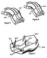
- Fig. 6 shows filler 200 attached to the base members 100.
- Fig. 7 is an isometric view of fixed cover 300.
- Latches 310 attach to base 100 at pocket 110.
- Ribs 320 are provided to enclose the side walls of the base to reduce the amount of movement that latches 310 move away from the base when impacted.
- Latches 330 latch onto the divider wall of the base 100 to provide additional resistance that resists the cover from lifting off the base.
- Ribs 340 pull cover 300 to the base 100 when the covers are installed.
- Slot 350 is provided to retain latch 450 from cover 400. The range of slot 350 is the same as slot 170 on the base.
- Fig. 8 is an isometric view of pivoting cover 400.
- Latches 410 attach to the base at pocket 110.
- Ribs 420 enclose the side walls of the base to reduce the amount of movement that latches 410 move away from the base when impacted.
- Latches 430 latch onto the divider wall 185 of the base 100 to provide additional resistance that resists the cover from lifting off the base.
- Ribs 440 align with the divider walls 185 on the base 100 to eliminate a gap, such that the cover passes regulatory standards.
- Latch 450 is provided to attach covers 300 and 400 together. When assembled, latch 450 moves inside of slot 350, allowing the covers 300, 400 to have the same amount of adjustment as the base members 100.
- Figs. 9-10 show attachment of the covers.
- Covers 300 and 400 are oriented in an appropriate position so that latch 450 can be inserted into slot 350 on both sides of cover 300 (Fig. 9). Once completed, the covers 300, 400 can be rotated to a suitable position, with the latches 450 on the inside of cover 300 holding the covers together (Fig. 10).
- the covers can be installed onto the base members 100.
- the base members and covers each have a same axis of rotation so that the covers connect to the base members regardless of orientation.
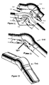
- Fig. 11 shows installation of the covers 300, 400 to the base 100.
- the covers slide down the base members simultaneously.
- Latches 310, 410 and 450 flex the covers 300, 400 away from the base members 100 as they are slid down.
- Ribs 320, 340 and 420 slide ' on the inside of the base's walls. This action pulls the covers into pockets 110.
- this action pushes down latches 450 used to connect the two covers 300, 400 so that they fit into pocket 160 and becomes an additional latch to help retain the covers on the base members.
- Ribs 340 then pull the covers 300, 400 to the base 100 and help the covers from moving away from the base when impacted. As the covers become fully seated on the base members, latches 330 and 440 latch onto the divider walls 185 of the base members 100. ,
- Fig. 12 shows an underside of the outside corner fitting 900 completely assembled.
- Latch 450 is seated underneath the base as shown and acts as an additional latch.
- Fig. 13 shows another view of the outside comer fitting 900 completely assembled.
- the hump in the cover accommodates bend radius control in the base so there is no reduction in capacity for cables being routed through the fitting.
- FIG. 14 illustrates the components of the inside corner fitting 1000, including two base members 500, filler 600, inside cover 700 and outside cover 800.
- the two base members 500 interlock with each other preferably allow the fitting to maintain a separation of channels.
- the base members also maintain a specified bend radius that is preferably 40 mm or greater (1.5").
- Filler 600 is provided to fill a gap that is created between the outside cover 800 and the inside cover 700 when the outside cover 800 is rotated relative to the inside cover 700.
- the covers 700, 800 are movable relative to each other, with cover 700 preferably being a fixed cover and outside cover 800 being a pivoting cover. However, this order can be reversed or both can be made pivotal.
- Base members 500 are provided with pockets 510 that accept latches 710 or 810 from either of the covers 700, 800.
- Pocket 520 is a recessed pocket that accepts a projection 560. Pocket 520 allows projection 560 to slide along it when the base 100 is rotated to an appropriate angle.
- boss 530 moves within a slot 570 when the base is rotated to the appropriate angle.
- Tabs 540 and divider walls 585 move inside of tabs 550 when the base is rotated.
- the divider walls 585 that line up to divider walls on the raceway section to which the fitting is attached are offset going through the fitting. As a result, the divider walls 585 will slide against each other and the tabs 540 will slide against tabs 550. This maintains the separation of channels at any angle within an allowable range.
- Tabs 580 line up the fitting to the ends of a raceway section (not shown).
- Holes 590 are screw holes that are provided to fasten the base to a wall or other surface.
- Radii 595 are formed to eliminate sharp corners that could damage wires when the fitting is rotated to a maximum obtuse angle.
- Fig. 16 shows the two base members 500 joined together.
- the unshown side includes the same structure as the visible side and operates the same.
- Pocket 520 accepts projection 560.
- projection 560 will slide inside of pockets 520.
- Tabs 540 from one base 500 will slide on top of tabs 550 from the other base, and vice versa.
- bosses 530 slide inside of slots 570.
- Figs. 17A-C show illustrations of the base members over an extreme range of motion, including an extreme acute angle (Fig. 17A), a moderate 90° angle (Fig. 17B), and an extreme obtuse angle (Fig. 17C) As shown, the base 500 maintains separation of channels throughout the full range of movement.
- Fig. 18 is a perspective view of inside cover 700.
- Latches 710 attach to the base 500 at pocket 510.
- Ribs 720 enclose the side wall of the base to reduce the distance that latches 710 move away from base 500 when the base is impacted.
- Latches 730 latch onto the divider wall 585 of the base 500 to provide additional resistance, preventing the cover from lifting off the base.
- Slot 740 retains latch 850 from outside cover 800.
- Fig. 19 is a perspective view of outside cover 800.
- Latches 810 attach to base 500 at pocket 510.
- Ribs 820 enclose the side wall of the base like ribs 720 to reduce the distance that latches 810 move away from base 500 when the base is impacted.
- Latches 830 attach onto the divider wall 585 of the base to provide additional resistance, preventing the cover 800 from lifting off of the base 500.
- Markings 840 such as score lines, can be provided to allow the user to rotate outside cover 800 to ensure that it makes certain predefined angles with inside cover 700.
- Latches 850 are used to attach covers 700, 800 together. When the covers 700, 800 are assembled, latch 850 moves inside of slot 740 allowing the covers to have the same amount of rotation as the base members.
- Figs. 20-21 show attachment of the covers 700, 800.
- the covers are oriented in a position such that latch 850 can be inserted into slot 740 on both sides of cover 700 (see Fig. 20). Once this is done, the covers 700, 800 can be rotated to an appropriate position, in which latches 850 are on the inside of cover 700 holding the two covers together (Fig. 21).
- covers 700, 800 Due to the rotation of covers 700, 800 at different angle inclinations, the covers may leave a gap between the base members' divider walls 585 and the cover that is greater than allowable. Additionally, outer cover 800 should fit snugly into the corner at different angles.
- filler 600 and score lines 840 are provided. First, as shown in Fig. 22, the end user measures the angle between the mounting surface or wall where the base members 500 have been or are to be secured. Then, the user snaps the inside cover 700 and outside cover 800 together and rotates the covers until the appropriate score line 840 lines up with the bottom edge of cover 700. The excess portion below the score line can then be removed from outside cover 800 using a knife and/or pliers.
- filler 600 which preferably is made of an elastic material, is placed into the outside cover 800 with chamfer 610 pressed up against an internal chamfer 860 of outside cover 800 with an opening 620 clearing latches 830 on the outside cover 800. Then, the user trims filler 600 with a knife until it matches the end of inside cover 700, making sure that both covers are at the appropriate angle. Then, the user places the filler 600 onto one of the base members 500 aligning its ribs with those of one of the base members 500 as shown in Fig. 23.
- covers 700, 800 are ready for installation.
- the covers and base members have a same axis of rotation. This ensures that the covers will connect to the base members at the same location regardless of the orientation.
- the covers 700, 800 have already been joined together and trimmed as discussed above.
- Fig. 24 illustrates further installation steps.
- the covers 700, 800 slide down base members 500 simultaneously. Latches 710, 810 and 850 flex the covers 700, 800 away from the base as they are slid down the base members 500. Ribs 720 and 820 slide down on the inside of the base members' walls. This pulls down the covers 700, 800 to the base members 500.
- Latches 710 and 810 engage the base members by fitting into pockets 510 while latches 850 slide down so as to fit within pockets 560, acting as additional latches to help in retaining the covers 700, 800 to the base members 500.
- latches 730 and 830 latch onto the divider walls 585 of the base members 500.
- Fig. 25 shows the underside of an assembled adjustable inside corner fitting 1000 according to a preferred embodiment of the invention with latch 850 seated underneath the base members.
- Fig. 26 shows a top view of the assembled inside corner fitting 1000.
Landscapes
- Engineering & Computer Science (AREA)
- Architecture (AREA)
- Civil Engineering (AREA)
- Structural Engineering (AREA)
- Details Of Indoor Wiring (AREA)
Claims (17)
- Joint d'angle ajustable (900) pour un système de conduites pour câbles, comprenant:dans lequel lesdits premier et deuxième couvercles courbes (300, 400) sont interconnectables l'un avec l'autre, permettant un déplacement pivotant relatif entre les deux, et sont interconnectables avec lesdits premier et deuxième éléments de base courbes (100) pour former un joint d'angle ajustable (900) pouvant être couplé à une section de conduite pour câbles et pouvant être positionné à une de plusieurs configurations angulaires à l'intérieur d'une plage de déplacement angulaire définie par ladite au moins une fente (170) sur ledit au moins un desdits éléments de base (100).des premier et deuxième éléments de base courbes interconnectables (100), un desdits éléments de base présentant au moins une fente courbe (170), et l'autre desdits éléments de base comportant au moins un renflement (130) pouvant être positionné à l'intérieur de ladite au moins une fente (170), ladite fente courbe (170) présentant une courbure et une longueur qui bloquent ladite au moins un renflement (130) à l'intérieur de ladite au moins une fente (170) et qui permettent le pivotement dudit premier élément de base (100) par rapport audit deuxième élément de base (100) autour d'un point de pivot à l'intérieur d'une plage déterminée de déplacement angulaire relatif lorsque lesdits premier et deuxième éléments de base courbes interconnectables (100) sont couplés;des premier et deuxième couvercles courbes (300, 400), un desdits couvercles présentant au moins une fente (350), et l'autre desdits couvercles comportant au moins un verrou (450) pouvant être positionné à l'intérieur de ladite au moins une fente (350) dudit un couvercle; etune structure de montage (160) qui monte lesdits premier et deuxième couvercles (300, 400) sur lesdits premier et deuxième éléments de base (100),
- Joint d'angle ajustable (900) selon la revendication 1, dans lequel ledit joint d'angle (900) est un joint d'angle extérieur, ou dans lequel ledit joint d'angle est un joint d'angle intérieur.
- Joint d'angle ajustable selon la revendication 1, dans lequel lesdits premier et deuxième éléments de base (100) et lesdits premier et deuxième couvercles (300, 400), lorsqu'ils sont interconnectés, forment au moins un canal s'étendant longitudinalement et destiné à recevoir des câbles.
- Joint d'angle ajustable selon la revendication 3, dans lequel au moins une paroi de séparation d'étendant longitudinalement (185) est prévue sur chacun desdits premier et deuxième éléments de base (100), et dans lequel, de préférence, ladite au moins une paroi de séparation (185) de chacun desdits premier et deuxième éléments de base (100) est dimensionnée de manière à chevaucher tout en étant légèrement décalée par rapport à ladite au moins une paroi de séparation (185) correspondante de l'autre élément de base (100) de manière à former une pluralité de canaux s'étendant longitudinalement qui maintiennent une séparation entre les canaux d'un bout à l'autre de la totalité de la plage de déplacement relatif desdits premier et deuxième éléments de base (100).
- Joint d'angle ajustable (900) selon la revendication 3, dans lequel ledit au moins un canal conserve un rayon de courbure minimum prédéfini d'un bout à l'autre de la plage de déplacement du joint d'angle ajustable (900).
- Joint d'angle ajustable (900) selon la revendication 1, dans lequel ledit premier couvercle (300) est fixe, et ledit deuxième couvercle (400) peut pivoter par rapport audit premier couvercle (300).
- Joint d'angle ajustable selon la revendication 1, comprenant en outre un agent de remplissage (200) monté d'une façon opérationnelle sur le joint d'angle ajustable (900) pour remplir un espace créé entre lesdits premier et deuxième couvercles (300, 400), et dans lequel, de préférence, ledit agent de remplissage (200) est élastique et peut se conformer à la courbure desdits éléments de base (100).
- Joint d'angle ajustable (900) selon la revendication 1, dans lequel au moins un desdits éléments de base (100) comprend des parois latérales comportant des nervures (320).
- Joint d'angle ajustable (900) selon la revendication 1, dans lequel la plage de déplacement pivotant définie par ladite fente (350) dudit un couvercle (300, 400) est la même que celle obtenue par ladite fente (170) dudit un élément de base (100).
- Joint d'angle ajustable (900) selon la revendication 1, dans lequel chacun des premier et deuxième éléments de base (100) présente une poche (110), et chacun des premier et deuxième couvercles (300, 400) comporte un verrou (310) qui s'attache à ladite poche (110) dans le but de retenir lesdits premier et deuxième couvercles (300, 400) sur lesdits premier et deuxième éléments de base (100).
- Joint d'angle ajustable (900) selon la revendication 1, dans lequel ledit premier élément de base (100) comporte au moins une patte (140) qui tourne à l'intérieur d'un patte correspondante (150) dudit deuxième élément de base (100) durant la rotation relative desdits premier et deuxième éléments de base (100).
- Joint d'angle ajustable selon la revendication 1, dans lequel les premier et deuxième éléments de base (100) peuvent tourner pour former un angle aigu ou un angle obtus ou un angle droit entre les premier et deuxième éléments de base (100).
- Joint d'angle ajustable selon la revendication 1, dans lequel un desdits couvercles (300, 400) comporte des marques (840) indiquant l'angle de rotation.
- Procédé pour former un joint d'angle (900) d'un système de conduites pour câbles présentant une configuration angulaire prédéterminée, comprenant les étapes consistant à:fournir des premier et deuxième éléments de base courbes interconnectables (100), un desdits éléments de base présentant une fente courbe (170) et l'autre desdits éléments de base comportant un renflement (130) pouvant être positionné à l'intérieur de ladite fente (170), ladite fente courbe (170) présentant une courbure et une longueur qui bloquent ledit renflement (130) à l'intérieur de ladite fente (170) et qui permettent le pivotement dudit premier élément de base (100) par rapport audit deuxième élément de base (100) autour d'un point de pivot à l'intérieur d'une plage déterminée de déplacement angulaire relatif;fournir des premier et deuxième couvercles courbes (300, 400), un desdits couvercles présentant une fente (350), et l'autre desdits couvercles comportant un verrou (450) pouvant être positionné à l'intérieur de ladite fente (350) dudit un couvercle;coupler ledit renflement (130) desdits éléments de base (100) à ladite fente correspondante (170) desdits éléments de base afin d'interconnecter d'une façon pivotante lesdits premier et deuxième éléments de base;coupler ledit verrou (450) desdits couvercles (300, 400) à ladite fente correspondante (350) desdits couvercles afin d'interconnecter d'une façon pivotante lesdits premier et deuxième éléments de couvercle (300, 400);monter lesdits couvercles interconnectés (300, 400) sur lesdits éléments de base interconnectés (100)de manière à former un joint d'angle ajustable (900);déplacer d'une façon pivotante un desdits premier et deuxième éléments de base (100) par rapport à l'autre afin d'ajuster la configuration angulaire du joint d'angle ajustable (900) à un angle souhaité à l'intérieur d'une plage de déplacement angulaire définie par lesdites fentes (170).
- Procédé selon la revendication 14, dans lequel la plage de déplacement angulaire est limitée par ladite fente (170) et ledit renflement (130) desdits éléments de base (100), ou dans lequel la plage de déplacement angulaire est limitée par ladite fente (350) et ledit verrou (450) desdits éléments de couvercle (300, 400), ou dans lequel la plage de déplacement angulaire obtenue par ladite fente (170) desdits éléments de base (100) est la même que la plage de déplacement angulaire obtenue par ladite fente (350) desdits couvercles.
- Procédé selon la revendication 14, dans lequel l'étape de montage desdits couvercles (300, 400) sur lesdits éléments de base (100) comprend l'aménagement de poches (110, 120, 160) sur un des couvercles (300, 400) ou sur un des éléments de base (100), et l'installation de verrous (310, 330, 410, 430, 450) sur l'autre des couvercles (300, 400) ou des éléments de base (100), et le positionnement desdits couvercles (300, 400) et desdits éléments de base (100) de telle sorte que lesdits verrous s'attachent à certaines correspondantes desdites poches (110, 120, 160), ou comprenant en outre une étape consistant à attacher le joint d'angle ajustable (900) à un autre élément d'un système de conduites, ou dans lequel un desdits couvercles (300, 400) présente des marques (840) indiquant l'angle de rotation, la rotation faisant tourner un desdits éléments de base (100) par rapport à l'autre jusqu'à ce que lesdites marques (840) indiquent qu'un angle de rotation souhaité a été atteint.
- Procédé selon la revendication 14, comprenant en outre une étape consistant à fournir un agent de remplissage (200) destiné à combler tout espace entre lesdits premier et deuxième couvercles (300, 400) qui peut être créé durant la plage de déplacement desdits premier et deuxième éléments de base (100) l'un par rapport à l'autre, et dans lequel, de préférence, l'étape de fourniture d'un agent de remplissage (200) comprend la coupe d'un agent de remplissage à une taille souhaitée.
Applications Claiming Priority (2)
| Application Number | Priority Date | Filing Date | Title |
|---|---|---|---|
| US631471 | 2000-08-03 | ||
| US09/631,471 US6478499B1 (en) | 2000-08-03 | 2000-08-03 | Adjustable corner fitting |
Publications (3)
| Publication Number | Publication Date |
|---|---|
| EP1178251A2 EP1178251A2 (fr) | 2002-02-06 |
| EP1178251A3 EP1178251A3 (fr) | 2003-05-02 |
| EP1178251B1 true EP1178251B1 (fr) | 2005-01-26 |
Family
ID=24531343
Family Applications (1)
| Application Number | Title | Priority Date | Filing Date |
|---|---|---|---|
| EP01306620A Expired - Lifetime EP1178251B1 (fr) | 2000-08-03 | 2001-08-02 | Joint d'angle ajustable |
Country Status (3)
| Country | Link |
|---|---|
| US (1) | US6478499B1 (fr) |
| EP (1) | EP1178251B1 (fr) |
| DE (1) | DE60108569T2 (fr) |
Cited By (1)
| Publication number | Priority date | Publication date | Assignee | Title |
|---|---|---|---|---|
| CN101228677B (zh) * | 2005-05-25 | 2011-01-26 | 诺瓦Ed&S有限公司 | 用于电缆线槽系统的转角配件 |
Families Citing this family (33)
| Publication number | Priority date | Publication date | Assignee | Title |
|---|---|---|---|---|
| FR2825527B1 (fr) * | 2001-06-01 | 2003-09-05 | Legrand Sa | Accessoire d'angle pour goulotte |
| US6972367B2 (en) | 2001-10-31 | 2005-12-06 | Hellermanntyton Corporation | Multi-channel raceway |
| EP1355397A1 (fr) * | 2002-03-28 | 2003-10-22 | C & C MARSHALL LIMITED | Structure d'angle pour un canal fournisseur de services et assemblage d'angle |
| FR2857791B1 (fr) * | 2003-07-15 | 2005-09-16 | Legrand Sa | Accessoire pour goulotte a verrouillage automatique |
| FR2861905B1 (fr) * | 2003-11-05 | 2007-03-02 | Legrand Sa | Accessoire de raccordement d'angle pour goulottes comprenant un compartiment derive |
| FR2861906B1 (fr) * | 2003-11-05 | 2006-01-13 | Legrand Sa | Accessoire d'angle pour goulottes comprenant deux volets assembles en biais |
| AU2005304894A1 (en) * | 2004-11-04 | 2006-05-18 | David H. Johnston | Channel unit with adjustable corner |
| EP1893826A4 (fr) * | 2005-05-11 | 2010-01-13 | J G Starew Innovative Solution | Systeme de guidage a passages multiples |
| USD552221S1 (en) * | 2006-05-16 | 2007-10-02 | Beutler Corporation | Downspout side elbow coupling |
| USD552220S1 (en) * | 2006-05-16 | 2007-10-02 | Beutler Corporation | Downspout discharge elbow |
| USD552219S1 (en) * | 2006-05-16 | 2007-10-02 | Beutler Corporation | Downspout elbow coupling |
| USD555232S1 (en) * | 2006-05-16 | 2007-11-13 | Beutler Corporation | Downspout side discharge elbow |
| GB0613073D0 (en) * | 2006-07-03 | 2006-08-09 | Rehau Ltd | Fittings for cable trunking |
| FR2924868B1 (fr) * | 2007-12-06 | 2010-01-15 | Inovac | Accessoire d'angle pour goulottes a volets pivotants |
| FR2924867B1 (fr) * | 2007-12-06 | 2010-01-01 | Inovac | Accessoire d'angle pour goulottes |
| US8013259B2 (en) * | 2008-06-11 | 2011-09-06 | Panduit Corp. | Multi position divider clip |
| US8251543B2 (en) * | 2008-11-22 | 2012-08-28 | Innovative Lighting, Inc. | Interior corner mounting module for rope light system |
| DE102009008684B4 (de) * | 2009-02-06 | 2011-03-10 | Maico Elektroapparate-Fabrik Gmbh | Befestigungselement, Vorrichtung sowie Verfahren zum Befestigen eines flexiblen Rohres |
| DE202009013622U1 (de) | 2009-10-09 | 2011-02-24 | Tehalit Gmbh | Winkelformteil für Kabelkanäle |
| CN102148483A (zh) * | 2010-06-01 | 2011-08-10 | 广东联塑科技实业有限公司 | 一种线槽外角结构 |
| CN102148484A (zh) * | 2010-06-01 | 2011-08-10 | 广东联塑科技实业有限公司 | 一种线槽内角结构 |
| US20130000097A1 (en) * | 2011-06-29 | 2013-01-03 | Pino Angelo J | Raceway molding system device and method |
| CN103855654A (zh) * | 2012-12-05 | 2014-06-11 | 丹阳市飞越车辆附件有限公司 | 线束拐角支架 |
| GB2510875B (en) * | 2013-02-15 | 2016-08-24 | Ppc Broadband Fiber Ltd | Bracket |
| CN103872595B (zh) * | 2014-03-28 | 2016-02-17 | 国家电网公司 | 变压器的模块化接线和排线装置 |
| EP3098495B1 (fr) * | 2015-05-27 | 2018-04-04 | Cooper-Standard Automotive (Deutschland) GmbH | Clip de support et ensemble de tuyaux |
| JP6940488B2 (ja) * | 2015-09-18 | 2021-09-29 | トリース メディカル コンセプツ,インコーポレイティド | 継手スペーサシステム及び方法 |
| US12444914B2 (en) | 2016-02-25 | 2025-10-14 | T&B Cable Tray Canada Ltd. | Splice plate assembly for cable tray |
| JP6762835B2 (ja) * | 2016-10-12 | 2020-09-30 | 未来工業株式会社 | 配線・配管材保護カバー |
| USD846087S1 (en) * | 2017-09-14 | 2019-04-16 | Naber Holding Gmbh & Co. Kg | Pipe fitting |
| DE102019219182B4 (de) | 2019-12-09 | 2025-08-28 | Abb Ag | Kabelbefestigungszubehör |
| CN111237012B (zh) * | 2020-03-13 | 2024-09-03 | 中铁第四勘察设计院集团有限公司 | 离壁沟 |
| CN113972607B (zh) * | 2021-11-05 | 2023-05-30 | 河南中坤实业有限公司 | 一种槽式电缆桥架 |
Family Cites Families (18)
| Publication number | Priority date | Publication date | Assignee | Title |
|---|---|---|---|---|
| US1727772A (en) | 1926-05-03 | 1929-09-10 | Paul M Hotchkin | Joint for lighting systems |
| AT380918B (de) | 1982-07-23 | 1986-07-25 | Siegenia Frank Kg | Eckumlenkung fuer treibstangenbeschlaege von fenstern, tueren od. dgl. |
| US4779901A (en) * | 1983-12-29 | 1988-10-25 | Eg&G Pressure Science, Inc. | Sealed rigid pipe joint |
| KR890003205Y1 (ko) | 1986-03-04 | 1989-05-17 | 주식회사 우경제작소 | 절첩식 사다리용 경첩 |
| FR2608726A1 (fr) | 1986-12-23 | 1988-06-24 | Wahl Michel | Coude de canalisation a angle variable |
| US5211602A (en) | 1989-04-13 | 1993-05-18 | J H Plymoth Ab | Arrangement in fume extraction arms |
| GB9022179D0 (en) * | 1990-10-12 | 1990-11-28 | Rich Muller Limited | Fishplate |
| GB9214258D0 (en) * | 1992-07-04 | 1992-08-19 | Swifts Of Scarborough Ltd | Improvements relating to support systems for cables,service pipes and the like |
| JPH0666395A (ja) | 1992-08-20 | 1994-03-08 | Maezawa Kasei Ind Co Ltd | 自在管継手 |
| US5375891A (en) | 1992-12-14 | 1994-12-27 | Metro Eavestroughing Ltd. | Universal connector for downspout drainage extensions |
| US5470021A (en) * | 1993-11-05 | 1995-11-28 | Mphusky Corporation | Cable support apparatus and method |
| US5469893A (en) * | 1993-12-21 | 1995-11-28 | Panduit Corp. | Tab and slot fiber optic fitting |
| US5753855A (en) * | 1994-11-17 | 1998-05-19 | Panduit Corp. | Wiring duct fittings |
| US5621994A (en) | 1995-05-04 | 1997-04-22 | Apco Graphics, Inc. | Sign assembly with adjustable corners |
| JP3116828B2 (ja) * | 1996-06-27 | 2000-12-11 | 日立プラント建設株式会社 | ケーブル配線棚 |
| US5960958A (en) * | 1997-05-28 | 1999-10-05 | Thomas & Betts Corporation | Cable tray packaging |
| FR2768571B1 (fr) | 1997-09-16 | 1999-11-19 | Planet Wattohm Sa | Dispositif de recouvrement variable pour conduit de cablage electrique |
| IT1303627B1 (it) * | 1998-08-05 | 2000-11-15 | Bocchiotti Soc Ind Elettrotec | Raccordo angolare registrabile per canalette portacavi o simili. |
-
2000
- 2000-08-03 US US09/631,471 patent/US6478499B1/en not_active Expired - Fee Related
-
2001
- 2001-08-02 DE DE60108569T patent/DE60108569T2/de not_active Expired - Fee Related
- 2001-08-02 EP EP01306620A patent/EP1178251B1/fr not_active Expired - Lifetime
Cited By (1)
| Publication number | Priority date | Publication date | Assignee | Title |
|---|---|---|---|---|
| CN101228677B (zh) * | 2005-05-25 | 2011-01-26 | 诺瓦Ed&S有限公司 | 用于电缆线槽系统的转角配件 |
Also Published As
| Publication number | Publication date |
|---|---|
| EP1178251A3 (fr) | 2003-05-02 |
| DE60108569T2 (de) | 2006-01-05 |
| EP1178251A2 (fr) | 2002-02-06 |
| DE60108569D1 (de) | 2005-03-03 |
| US6478499B1 (en) | 2002-11-12 |
Similar Documents
| Publication | Publication Date | Title |
|---|---|---|
| EP1178251B1 (fr) | Joint d'angle ajustable | |
| US7224880B2 (en) | Cable trough cover | |
| US6609684B2 (en) | Flexible snap-together cable trough | |
| US11662041B2 (en) | Support clip | |
| EP1684104B1 (fr) | Goulotte de sortie de câble optique surbaissée | |
| US6915056B2 (en) | Cable exit trough with insert | |
| EP1323220B1 (fr) | Chemin de cables comportant des elements lateraux separes | |
| EP2136447A1 (fr) | Système de gestion de câbles pour un système de réseau de plancher surélevé | |
| RU2382462C2 (ru) | Компенсационное устройство для кабельного канала, устанавливаемого по периметру поверхности | |
| WO2001095003A2 (fr) | Chemin de cables telescopique | |
| US20030128530A1 (en) | Incrementally-adjustable wiring tray and hinged wiring tray cover | |
| US20030051892A1 (en) | Cable channel assembly | |
| EP0742458A2 (fr) | Articulation adaptateur pour cassette de raccordement de fibres optiques | |
| US6448495B1 (en) | Fiber optic cable raceway outlet with raceway cover, and method | |
| US20090189025A1 (en) | Telescoping cover for cable trough system | |
| US20030177628A1 (en) | Cable ducting joiner | |
| US20020094184A1 (en) | Fiber optic cable raceway outlet and method | |
| US20160116700A1 (en) | Cable routing system exit structure | |
| EP0804662B1 (fr) | Structure de moule pour tubes noyes | |
| EP1944847A2 (fr) | Boîte d'installation avec dispositif de montage amovible | |
| EP4737968A1 (fr) | Boîte de distribution de fibres haute densité | |
| EP1829179B1 (fr) | Raccord destine a joindre des unites d'acheminement de cables | |
| WO2004003617A1 (fr) | Conduit de sortie pour fibres optiques | |
| US20050066873A1 (en) | Utility service protection strip | |
| HK1058068B (en) | Cable exit trough with insert |
Legal Events
| Date | Code | Title | Description |
|---|---|---|---|
| PUAI | Public reference made under article 153(3) epc to a published international application that has entered the european phase |
Free format text: ORIGINAL CODE: 0009012 |
|
| AK | Designated contracting states |
Kind code of ref document: A2 Designated state(s): AT BE CH CY DE DK ES FI FR GB GR IE IT LI LU MC NL PT SE TR |
|
| AX | Request for extension of the european patent |
Free format text: AL;LT;LV;MK;RO;SI |
|
| PUAL | Search report despatched |
Free format text: ORIGINAL CODE: 0009013 |
|
| AK | Designated contracting states |
Designated state(s): AT BE CH CY DE DK ES FI FR GB GR IE IT LI LU MC NL PT SE TR |
|
| AX | Request for extension of the european patent |
Extension state: AL LT LV MK RO SI |
|
| 17P | Request for examination filed |
Effective date: 20031003 |
|
| AKX | Designation fees paid |
Designated state(s): DE FR GB IT |
|
| 17Q | First examination report despatched |
Effective date: 20040112 |
|
| GRAP | Despatch of communication of intention to grant a patent |
Free format text: ORIGINAL CODE: EPIDOSNIGR1 |
|
| GRAS | Grant fee paid |
Free format text: ORIGINAL CODE: EPIDOSNIGR3 |
|
| GRAA | (expected) grant |
Free format text: ORIGINAL CODE: 0009210 |
|
| AK | Designated contracting states |
Kind code of ref document: B1 Designated state(s): DE FR GB IT |
|
| REG | Reference to a national code |
Ref country code: IE Ref legal event code: FG4D Ref country code: GB Ref legal event code: FG4D |
|
| REF | Corresponds to: |
Ref document number: 60108569 Country of ref document: DE Date of ref document: 20050303 Kind code of ref document: P |
|
| PGFP | Annual fee paid to national office [announced via postgrant information from national office to epo] |
Ref country code: GB Payment date: 20050727 Year of fee payment: 5 |
|
| PGFP | Annual fee paid to national office [announced via postgrant information from national office to epo] |
Ref country code: DE Payment date: 20050728 Year of fee payment: 5 |
|
| PGFP | Annual fee paid to national office [announced via postgrant information from national office to epo] |
Ref country code: FR Payment date: 20050809 Year of fee payment: 5 |
|
| PLBE | No opposition filed within time limit |
Free format text: ORIGINAL CODE: 0009261 |
|
| STAA | Information on the status of an ep patent application or granted ep patent |
Free format text: STATUS: NO OPPOSITION FILED WITHIN TIME LIMIT |
|
| ET | Fr: translation filed | ||
| 26N | No opposition filed |
Effective date: 20051027 |
|
| PGFP | Annual fee paid to national office [announced via postgrant information from national office to epo] |
Ref country code: IT Payment date: 20060831 Year of fee payment: 6 |
|
| PG25 | Lapsed in a contracting state [announced via postgrant information from national office to epo] |
Ref country code: DE Free format text: LAPSE BECAUSE OF NON-PAYMENT OF DUE FEES Effective date: 20070301 |
|
| GBPC | Gb: european patent ceased through non-payment of renewal fee |
Effective date: 20060802 |
|
| REG | Reference to a national code |
Ref country code: FR Ref legal event code: ST Effective date: 20070430 |
|
| PG25 | Lapsed in a contracting state [announced via postgrant information from national office to epo] |
Ref country code: GB Free format text: LAPSE BECAUSE OF NON-PAYMENT OF DUE FEES Effective date: 20060802 |
|
| PG25 | Lapsed in a contracting state [announced via postgrant information from national office to epo] |
Ref country code: FR Free format text: LAPSE BECAUSE OF NON-PAYMENT OF DUE FEES Effective date: 20060831 |
|
| PG25 | Lapsed in a contracting state [announced via postgrant information from national office to epo] |
Ref country code: IT Free format text: LAPSE BECAUSE OF NON-PAYMENT OF DUE FEES Effective date: 20070802 |