EP1178573A2 - Connecteur pour circuit imprimé flexible - Google Patents
Connecteur pour circuit imprimé flexible Download PDFInfo
- Publication number
- EP1178573A2 EP1178573A2 EP01117910A EP01117910A EP1178573A2 EP 1178573 A2 EP1178573 A2 EP 1178573A2 EP 01117910 A EP01117910 A EP 01117910A EP 01117910 A EP01117910 A EP 01117910A EP 1178573 A2 EP1178573 A2 EP 1178573A2
- Authority
- EP
- European Patent Office
- Prior art keywords
- flex
- flex film
- connection arrangement
- arrangement according
- contact
- Prior art date
- Legal status (The legal status is an assumption and is not a legal conclusion. Google has not performed a legal analysis and makes no representation as to the accuracy of the status listed.)
- Withdrawn
Links
Images


Classifications
-
- H—ELECTRICITY
- H01—ELECTRIC ELEMENTS
- H01R—ELECTRICALLY-CONDUCTIVE CONNECTIONS; STRUCTURAL ASSOCIATIONS OF A PLURALITY OF MUTUALLY-INSULATED ELECTRICAL CONNECTING ELEMENTS; COUPLING DEVICES; CURRENT COLLECTORS
- H01R13/00—Details of coupling devices of the kinds covered by groups H01R12/70 or H01R24/00 - H01R33/00
- H01R13/58—Means for relieving strain on wire connection, e.g. cord grip, for avoiding loosening of connections between wires and terminals within a coupling device terminating a cable
- H01R13/582—Means for relieving strain on wire connection, e.g. cord grip, for avoiding loosening of connections between wires and terminals within a coupling device terminating a cable the cable being clamped between assembled parts of the housing
- H01R13/5829—Means for relieving strain on wire connection, e.g. cord grip, for avoiding loosening of connections between wires and terminals within a coupling device terminating a cable the cable being clamped between assembled parts of the housing the clamping part being flexibly or hingedly connected to the housing
-
- H—ELECTRICITY
- H01—ELECTRIC ELEMENTS
- H01R—ELECTRICALLY-CONDUCTIVE CONNECTIONS; STRUCTURAL ASSOCIATIONS OF A PLURALITY OF MUTUALLY-INSULATED ELECTRICAL CONNECTING ELEMENTS; COUPLING DEVICES; CURRENT COLLECTORS
- H01R12/00—Structural associations of a plurality of mutually-insulated electrical connecting elements, specially adapted for printed circuits, e.g. printed circuit boards [PCB], flat or ribbon cables, or like generally planar structures, e.g. terminal strips, terminal blocks; Coupling devices specially adapted for printed circuits, flat or ribbon cables, or like generally planar structures; Terminals specially adapted for contact with, or insertion into, printed circuits, flat or ribbon cables, or like generally planar structures
- H01R12/70—Coupling devices
- H01R12/77—Coupling devices for flexible printed circuits, flat or ribbon cables or like structures
- H01R12/771—Details
- H01R12/774—Retainers
-
- H—ELECTRICITY
- H01—ELECTRIC ELEMENTS
- H01R—ELECTRICALLY-CONDUCTIVE CONNECTIONS; STRUCTURAL ASSOCIATIONS OF A PLURALITY OF MUTUALLY-INSULATED ELECTRICAL CONNECTING ELEMENTS; COUPLING DEVICES; CURRENT COLLECTORS
- H01R12/00—Structural associations of a plurality of mutually-insulated electrical connecting elements, specially adapted for printed circuits, e.g. printed circuit boards [PCB], flat or ribbon cables, or like generally planar structures, e.g. terminal strips, terminal blocks; Coupling devices specially adapted for printed circuits, flat or ribbon cables, or like generally planar structures; Terminals specially adapted for contact with, or insertion into, printed circuits, flat or ribbon cables, or like generally planar structures
- H01R12/70—Coupling devices
- H01R12/82—Coupling devices connected with low or zero insertion force
- H01R12/85—Coupling devices connected with low or zero insertion force contact pressure producing means, contacts activated after insertion of printed circuits or like structures
- H01R12/88—Coupling devices connected with low or zero insertion force contact pressure producing means, contacts activated after insertion of printed circuits or like structures acting manually by rotating or pivoting connector housing parts
Definitions
- the present invention relates to a flex foil contact arrangement according to the preamble of the independent claim as well as a flex foil conductor.
- Flex foils are thin plastic foils on which one or several metallic conductor tracks, in particular Cu tracks, attached are. These flex foils are characterized by their small size Weight and due to the thin material by their Flexibility. With a correspondingly wide conductor track design are the foils not only for data signal transmission, but also for the energy supply of Can be used by consumers such as LEDs etc. It is also there already known, contact arrangements at the ends of the flex foils to be provided on which the flex film is contacted.
- the object of the present invention is to create something new to provide for commercial use.
- the solution this task is claimed independently. Preferred embodiments can be found in the subclaims.
- a first essential aspect of the invention sees one Flex film connection arrangement with a contact surface for the Contact area of a supplied flex film and flex film recesses engaging means penetrating near the contact surface in which it is provided that the engagement means the Penetrate the flex film opposite the feed side.
- a first basic idea of the invention is therefore by locating the engaging means away from both the trace as well as the contact area not just a general one To achieve fixation, but also a flat layer of the flex film at the contact area by placing an engaging force behind this is exercised.
- protection for the contact area provided to such as prefabricated during transportation and lead foils provided with terminals, protecting them to cause, especially against kinking and / or soiling.
- Protection can be provided by a general around the flex film end U-shaped, preferably with a groove circumferential border be formed, the protection continues may include an upper cover.
- the groove-like grip the edge of the conductor foil at the contact area is per se, and especially regardless of the presence of a rear Flex film flat layer engaging means advantageous.
- the cover can be provided a contact window and at the same time can also complete the cover with the cover bordered conductor track end to the conductor track except for one corresponding passage area can be effected.
- the cover is in a preferred embodiment have a single contact window for all contact pins, the contact surface itself being longer than the contact area and the window above it will be so one Lying flat also in the contact areas if possible to ensure separable elongated holes in a preferred Example of use that form flexible film recesses.
- the engagement means can be a plurality of pins or the like have, which penetrate through the conductor track and with this leaving in particular a sufficient lateral Play in positive engagement. It is on the feed side opposite side, that is close to or immediately at the end of the conductor track, preferably a single one Pin provided that the flex film only on the support surface must tighten, while preferably further pins are provided are to hold back the entire slide and so one To effect strain relief on the contacts.
- cones are on the cover arranged so that when the lid is folded down the First step through the slots and then through the corresponding ones Recesses on or on the contact surface.
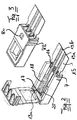
- 1 comprises a flex foil contact arrangement, generally designated 1 1 a base 2 with a support surface 3 and a lid 4, which has a film hinge 5 with the base 2 is connected.
- the base 2 has a generally U-shaped circumferential wall 6 provided, wherein the U is open on the feed side, so closed the side from which a flexible film end is inserted 3, the side walls 6 are open the height of the support surface 3 with a forward (feed side) lateral groove extending to the rear 7 provided.
- a locking lug 8a for cooperation provided with a locking arrangement 8b, which as side cheeks are formed on the cover 4, around which the film hinge 5 to be able to snap-in cover 4.
- the U-shaped side wall is close to the support area 3 lower than the feed side, the different heights Areas are connected to each other by a ramp 9.
- a series of holding cams 11a facing the base are provided, in corresponding holding cam recesses 11b the base 2 intervene.
- a pin 13a is provided centrally, which in an elongated Recess 13b in the base 2 can be pivoted.
- the Pin 13a is directly next to a window 14 in the Cover 4 is provided, which has such a clear width, that contact finger 20 on a socket (see Fig. 5) can penetrate through the window 14.
- a latching arrangement 8c for latching the arrangement provided in a socket.
- the flex foil contact arrangement that is to say the flex foil plug according to the present invention is used as follows:
- a flexible film 15 of suitable width 15 (compare Fig. 4) with elongated holes 16 and 17 before under behind provided their contact area 18.
- the flex film 15 in the lateral grooves 7 between the wall 6 and base 2 of the Flex film contact assembly 1 inserted until it at the rear End of the flex foil contact assembly 1 abuts.
- the flex film is now correctly aligned and against the side Move protected on base 2.
- the Lid 4 swung down.
- the pin 13a penetrates the slot 17, which between two conductor tracks 19a, 19b is arranged in a region 20 free of conductor tracks, and will then pivoted into the recess 13. This already results mechanical contact between pin 13a and the flex film 15 before the holding cams 11a close to the flex film are.
- the flex film is pulled backwards and in Contact area streamlined. Then penetrate the holding cams 11a the elongated holes 16 in the flexible film 15 and get into the Retaining cam recesses 11b at the base 2. The flex film is pulled slightly inwards, for which the back, So beveled to the inside of the side edge of the Holding cam 11a then contributes to the side cheeks 8b Engagement with the locking cams 8a and the plug cover 4 is locked at the base.
- the plug can now be inserted into a corresponding socket and there may be those in the socket existing contact pins in the socket on the conductor ends ultrasonically welded or otherwise permanent get connected.
- FIGS. 5 to 8 show a further exemplary embodiment, which differs from the previous one only in that that instead of the elongated holes penetrating cams 11b of the first variant as a front engagement means Press cams 11b 'are provided which the flex film does not pierce, but push down and so also in Interaction with the rear pin 13a 'a flat position the flex film in the contact area.
Landscapes
- Coupling Device And Connection With Printed Circuit (AREA)
Applications Claiming Priority (4)
| Application Number | Priority Date | Filing Date | Title |
|---|---|---|---|
| DE2000137648 DE10037648A1 (de) | 2000-07-31 | 2000-07-31 | Flexfolienstraffer |
| DE10038631 | 2000-07-31 | ||
| DE10037648 | 2000-07-31 | ||
| DE10038631 | 2000-07-31 |
Publications (2)
| Publication Number | Publication Date |
|---|---|
| EP1178573A2 true EP1178573A2 (fr) | 2002-02-06 |
| EP1178573A3 EP1178573A3 (fr) | 2003-02-05 |
Family
ID=26006587
Family Applications (1)
| Application Number | Title | Priority Date | Filing Date |
|---|---|---|---|
| EP01117910A Withdrawn EP1178573A3 (fr) | 2000-07-31 | 2001-07-24 | Connecteur pour circuit imprimé flexible |
Country Status (1)
| Country | Link |
|---|---|
| EP (1) | EP1178573A3 (fr) |
Cited By (3)
| Publication number | Priority date | Publication date | Assignee | Title |
|---|---|---|---|---|
| EP1710864A3 (fr) * | 2005-04-08 | 2008-03-26 | Tyco Electronics AMP K.K. | Connecteur électrique, faisceau de câbles et procédé pour arranger un faisceau de câbles |
| CN104078774A (zh) * | 2013-03-29 | 2014-10-01 | 海洋王(东莞)照明科技有限公司 | 一种导线连接装置 |
| FR3128066A1 (fr) * | 2021-10-07 | 2023-04-14 | Tyco Electronics France Sas | Dispositif de connexion électrique |
Family Cites Families (6)
| Publication number | Priority date | Publication date | Assignee | Title |
|---|---|---|---|---|
| US4406511A (en) * | 1981-07-29 | 1983-09-27 | Amp Incorporated | Flat cable connector strain relief |
| DE4041093C1 (fr) * | 1990-12-21 | 1992-04-02 | Karl Lumberg Gmbh & Co, 5885 Schalksmuehle, De | |
| US5356308A (en) * | 1991-10-31 | 1994-10-18 | Sumitomo Wiring Systems, Ltd. | Connector assembly for a flexible wiring plate |
| DE4217205C2 (de) * | 1992-05-23 | 1994-09-08 | Amphenol Tuchel Elect | Steckverbinder |
| JP3107121B2 (ja) * | 1992-12-18 | 2000-11-06 | 矢崎総業株式会社 | フラット電線とコネクタのロック構造 |
| US5934933A (en) * | 1997-06-20 | 1999-08-10 | Cts Corporation | Snap lock membrane connector |
-
2001
- 2001-07-24 EP EP01117910A patent/EP1178573A3/fr not_active Withdrawn
Cited By (4)
| Publication number | Priority date | Publication date | Assignee | Title |
|---|---|---|---|---|
| EP1710864A3 (fr) * | 2005-04-08 | 2008-03-26 | Tyco Electronics AMP K.K. | Connecteur électrique, faisceau de câbles et procédé pour arranger un faisceau de câbles |
| CN104078774A (zh) * | 2013-03-29 | 2014-10-01 | 海洋王(东莞)照明科技有限公司 | 一种导线连接装置 |
| CN104078774B (zh) * | 2013-03-29 | 2016-04-27 | 海洋王(东莞)照明科技有限公司 | 一种导线连接装置 |
| FR3128066A1 (fr) * | 2021-10-07 | 2023-04-14 | Tyco Electronics France Sas | Dispositif de connexion électrique |
Also Published As
| Publication number | Publication date |
|---|---|
| EP1178573A3 (fr) | 2003-02-05 |
Similar Documents
| Publication | Publication Date | Title |
|---|---|---|
| DE69611320T2 (de) | Einführungskraftfreier elektrischer Verbinder für Flachkabel | |
| DE10250933B3 (de) | Verbinderanordnung zwischen einem Flex-Flachbandkabel und einer elektrischen Leiterplatte | |
| DE69934593T2 (de) | Niedrigprofil-Verbinderanordnung | |
| DE69121270T2 (de) | Zweiteilige Buchseneinheit für modularen Steckeraufbau | |
| DE2752117C2 (de) | Elektrisches Verbindergehäuse | |
| DE69529796T2 (de) | Doppelreihen-Flachstecker Verbinder mit geringer Höhe | |
| DE2732912A1 (de) | Elektrisches verbindungsteil | |
| DE2618758B2 (de) | Verbinder zur elektrischen Verbindung eines flachen, flexiblen Schaltungselements, wie z.B. eines Bandkabels | |
| DE2651216A1 (de) | Gedruckte leiterplatteneinheit | |
| DE2245982B2 (de) | Elektrischer Verbinder zur Herstellung einer Andrückverbindung mit einem Flachleiter eines Flachleiterkabels | |
| DE7921423U1 (de) | Elektrisches Verbindergehäuse | |
| DE2212807C2 (de) | Elektrische Verbinderanordnung | |
| DE2307437A1 (de) | Kabelschuh fuer elektrische leitungen | |
| DE2827487C2 (fr) | ||
| DE10008932A1 (de) | Elektrischer Stecker | |
| DE10065972A1 (de) | Flexfoliensteckerzugentlastung | |
| DE1590048C3 (de) | AnschluBstecker für ein Bandkabel | |
| DE2743648C3 (de) | Aufnahmevorrichtung zur Aufnahme von mit gedruckten Schaltungsplatten bestückten Gehäusen insbesondere der elektrischen Nachrichtenübertragungstechnik | |
| DE102005028512A1 (de) | Stecker | |
| DE3879986T2 (de) | Elektrischer Verbinder. | |
| DE3603250C2 (fr) | ||
| EP1178573A2 (fr) | Connecteur pour circuit imprimé flexible | |
| DE69023166T2 (de) | Elektrischer Verbinder. | |
| DE2844576A1 (de) | Baugruppentraeger | |
| DE2106178B2 (de) | Elektrischer Kontakt |
Legal Events
| Date | Code | Title | Description |
|---|---|---|---|
| PUAI | Public reference made under article 153(3) epc to a published international application that has entered the european phase |
Free format text: ORIGINAL CODE: 0009012 |
|
| AK | Designated contracting states |
Kind code of ref document: A2 Designated state(s): AT BE CH CY DE DK ES FI FR GB GR IE IT LI LU MC NL PT SE TR |
|
| AX | Request for extension of the european patent |
Free format text: AL;LT;LV;MK;RO;SI |
|
| PUAL | Search report despatched |
Free format text: ORIGINAL CODE: 0009013 |
|
| AK | Designated contracting states |
Designated state(s): AT BE CH CY DE DK ES FI FR GB GR IE IT LI LU MC NL PT SE TR |
|
| AX | Request for extension of the european patent |
Extension state: AL LT LV MK RO SI |
|
| RIC1 | Information provided on ipc code assigned before grant |
Ipc: 7H 01R 9/07 B Ipc: 7H 01R 13/58 B Ipc: 7H 01R 13/50 A |
|
| AKX | Designation fees paid | ||
| REG | Reference to a national code |
Ref country code: DE Ref legal event code: 8566 |
|
| STAA | Information on the status of an ep patent application or granted ep patent |
Free format text: STATUS: THE APPLICATION IS DEEMED TO BE WITHDRAWN |
|
| 18D | Application deemed to be withdrawn |
Effective date: 20030806 |