EP1179162B1 - Paneel aus hochisoliertem elektrothermischen gewebe - Google Patents
Paneel aus hochisoliertem elektrothermischen gewebe Download PDFInfo
- Publication number
- EP1179162B1 EP1179162B1 EP99929698A EP99929698A EP1179162B1 EP 1179162 B1 EP1179162 B1 EP 1179162B1 EP 99929698 A EP99929698 A EP 99929698A EP 99929698 A EP99929698 A EP 99929698A EP 1179162 B1 EP1179162 B1 EP 1179162B1
- Authority
- EP
- European Patent Office
- Prior art keywords
- panel
- generating
- fabric
- heat
- diffusing heat
- Prior art date
- Legal status (The legal status is an assumption and is not a legal conclusion. Google has not performed a legal analysis and makes no representation as to the accuracy of the status listed.)
- Expired - Lifetime
Links
Images

Classifications
-
- F—MECHANICAL ENGINEERING; LIGHTING; HEATING; WEAPONS; BLASTING
- F24—HEATING; RANGES; VENTILATING
- F24D—DOMESTIC- OR SPACE-HEATING SYSTEMS, e.g. CENTRAL HEATING SYSTEMS; DOMESTIC HOT-WATER SUPPLY SYSTEMS; ELEMENTS OR COMPONENTS THEREFOR
- F24D13/00—Electric heating systems
- F24D13/02—Electric heating systems solely using resistance heating, e.g. underfloor heating
- F24D13/022—Electric heating systems solely using resistance heating, e.g. underfloor heating resistances incorporated in construction elements
-
- Y—GENERAL TAGGING OF NEW TECHNOLOGICAL DEVELOPMENTS; GENERAL TAGGING OF CROSS-SECTIONAL TECHNOLOGIES SPANNING OVER SEVERAL SECTIONS OF THE IPC; TECHNICAL SUBJECTS COVERED BY FORMER USPC CROSS-REFERENCE ART COLLECTIONS [XRACs] AND DIGESTS
- Y02—TECHNOLOGIES OR APPLICATIONS FOR MITIGATION OR ADAPTATION AGAINST CLIMATE CHANGE
- Y02B—CLIMATE CHANGE MITIGATION TECHNOLOGIES RELATED TO BUILDINGS, e.g. HOUSING, HOUSE APPLIANCES OR RELATED END-USER APPLICATIONS
- Y02B30/00—Energy efficient heating, ventilation or air conditioning [HVAC]
-
- Y—GENERAL TAGGING OF NEW TECHNOLOGICAL DEVELOPMENTS; GENERAL TAGGING OF CROSS-SECTIONAL TECHNOLOGIES SPANNING OVER SEVERAL SECTIONS OF THE IPC; TECHNICAL SUBJECTS COVERED BY FORMER USPC CROSS-REFERENCE ART COLLECTIONS [XRACs] AND DIGESTS
- Y10—TECHNICAL SUBJECTS COVERED BY FORMER USPC
- Y10T—TECHNICAL SUBJECTS COVERED BY FORMER US CLASSIFICATION
- Y10T29/00—Metal working
- Y10T29/49—Method of mechanical manufacture
- Y10T29/49002—Electrical device making
- Y10T29/49082—Resistor making
- Y10T29/49083—Heater type
Definitions
- the invention concerns means for generating heat for indoor use by electric current.
- document US-A-2 573 120 discloses a panel made with electrothermal fabric for generating and diffusing heat, the panel consisting of a heat-radiating board comprising electrothermal fabric with a weft wave of highly conductive wire, which is small in diameter and considerable in length, covered with insulating material, having ends provided with electric contacts, said board being completed by external layers of electrothermal material.
- the means of heating are also bulky and, from the practical and aesthetic points of view, are difficult to combine with the furniture.
- the above invention according to claim 1 solves these problems, offering a means of electric heat that is flat, small in size and light in weight, as well as being highly insulated, as will be explained below.
- Subject of the disclosure is a panel for generation and diffusion of heat having on it an electrothermal fabric, and a board of heat radiating material consisting of one or more pieces of said fabric.
- Said fabric presents continuous weft wires, coated with highly insulating material and having electric contacts at their ends.
- thermoadhesive material complete the board, covered on both sides by a mica-based material.
- the weft wires By connecting the electric contacts to a source of electricity, the weft wires convert electric energy into thermal energy and, through the sheets of mica-based material, radiate heat throughout the environment.
- the warp threads of the pieces of fabric consist of thin parallel threads of fibre glass laid side by side.
- the weft wires run continuously from a first corner on a first side of the piece of fabric, crosswise to the weft wires, first passing above a first face of the first strip, above the second face of the next strip, above the first face of the strip next again, and so on till it reaches the opposite side of the piece.
- the highly conductive weft wire is of copper.
- the electric contacts are connected at the two ends of the wire that forms the weft weave, to be used to convert electric current into thermal energy, creating, by suitable means, a hole in the thermoadhesive layer that covers one face of the electrothermic sheet.
- This hole also passes through the insulation of the wire, a weld, or equivalent means, being put into said hole to connect said wire to an electric contact.
- the hole may be produced by a grinder, by sanding or by a laser beam.
- said beam penetrates the insulating lining on the metal wire of the weft weave, but is repelled by the metal itself.
- the heat radiating plate is mounted inside a protective frame.
- This frame consists of two halves, of a constant section at an angle of 90°, shape and internal dimensions corresponding to the external dimensions and shape of the main parts of the panel, and being provided with means for a stable assembly.
- the external dimensions of one half of the frame correspond to the internal dimensions of the other half.
- the shape of' the panel is preferably square.
- the external sheets of the panel are of micanite. This consists of small flakes of mica glued onto paper or cloth.
- the external sheets are of micarta.
- the supporting material for micarta is a fabric of fibreglass which can be impregnated with polyester or epoxy resins.
- a thermal sensor is placed centrally on the heat radiating plate; its contacts can be connected to the two ends of a break in the continuous wire that forms the weft.
- This sensor breaks the electric circuit of the heat-radiating plate when its temperature exceeds a certain level.
- the heat-radiating sheet comprises two superimposed pieces of electrothermal fabric with a thermoadhesive layer in between and at the ends.
- the weft wires of the two pieces of superimposed fabric can be connected in parallel or in series.
- thermoadhesive material is preferably epoxidic.
- the face of the heat-radiating board that will be on view can be covered with a sheet of decorative melamine.
- the invention offers evident advantages.
- the mica-based sheets ensure maximum electrical insulation and at the same time maximum diffusion of the heat on account of their being so thin, even only a few tenths of a millimetre thick, while at the same time ensuring good mechanical strength and maximum electrical insulation.
- the heat radiating plate also ensures maximum thermal efficiency, even though it is so thin, bulk and weight as well being minimum.
- the width and length of the panel can be decided as preferred, to make it useful for a variety of purposes.
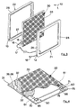
- Fig. 1 Panel with a heat-radiating board comprising a piece of electrothermal fabric, with surrounding frame, perspective.
- Fig. 2 Cross section of the panel.
- Fig. 3 An exploded view of the panel.
- Fig. 4 The heat-radiating board showing its component parts, perspective.
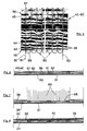
- Fig. 5 Detail of the electrothermal fabric comprised in the heat radiating board.
- FIG. 6 Detail of the heat-radiating board, a cross section.
- Fig. 7 As above with a laser making a blind hole.
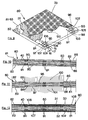
- Fig. 9 Heat-radiating board with two pieces of electrothermal fabric, perspective.
- Fig. 11 The board in Fig, 9 with a laser beam making two blind holes facing in opposite directions.
- the square panel 10 comprises the electrothermal sheet 30 protected by the frame 20 consisting of the two halves 21 and 22.
- the half-frame 21 presents a front 23 and edge 26 at 90°.
- the half frame 22 presents a front 27 and edge 28, also at 90°.
- the external dimensions of the half-frame 22 correspond to the internal dimensions of the other half 21 so that one fits firmly into the other to form a stable frame.
- the heat-radiating board 30 is formed of a piece 40 of special fabric placed between two layers, 35 and 36, of epoxidic thermoadhesive material and is clad on the two outer faces by pieces 31 and 32 of micanite.
- a decorative sheet 33 of melamine paper is laid on the surface to remain on view.
- the piece 40 of special fabric presents a warp 43-45 and a weft 50.
- the warp is formed of parallel strips 43-45 laid side by side, each strip being formed of fibreglass threads 46.
- the weft 50 is formed of a continuous copper wire 51 coated with insulating paint 52.
- the copper wire is inserted at one end, for example 55 (on the left low down in Fig. 5), of one side of the piece 40, crosswise to the fibreglass strips 43-45, passing alternatively on the first, on the second, on the first face, and so on, of the successive strips 43-45, emerging at the second end 56 (above, on the left, in the figure) of the opposite side of the piece, and after makng an 180°-bend 57, returns into the piece alongside the first already mentioned length of wire so returning to the first side 55.
- FIGS 6-8 show the method followed to do this.
- the holes 65, 66 are made by the laser beam 60 on the surface of the thermoadhesive layer 36. Said beam perforates the thermoadhesive layer 36 and the coating 52 on the copper wire 51.
- the electric contacts 75, 76 can therefore be connected at the two ends of the length of copper wire between the two holes, by welds 70, 71 made in the holes 65, 66.
- Said contacts 75, 76 are connected to the electric wires 15, 16 that bring in mains electricity through the cable 17 and plug 18.
- Figure 9 shows a heat-radiating board 80 comprising two pieces 40, 90 of special fabric with an intermediate layer 81 and two outer layers 82, 83 of epoxidic thermoadhesive material.
- the board is clad on its two surfaces by pieces of micanite 31, 32.
- Figures 9-12 show how mains electricity can be used to feed both the wefts 50 and 91 of copper wire in the pieces of fabric 40 and 90 by connecting the wires 15, 16 in the cable 17 to contacts 108, 109.
- wefts 50 and 91 become electrically connected in series.
- Figure 9 shows, practically in the centre of the upper surface of the heat-radiating board 80, a discoid sensor 120 with switch whose contacts are connected to the two separated ends of the copper warp below said upper surface.
- the switch in said sensor automatically opens thus opening the electric circuit and preventing further generation of heat until the temperature has fallen to the pre-set level.
- the electric cable 17, with plug 18 passes through the two opposite cavities, respectively 12 in the half frame 21 and 13 in the half frame 22.
- the copper weft wires 50 and 91 in the pieces ot thermoelectric fabric 40 and 80 receive current and heat up to a moderate temperature of about 100°C, the heat so generated, on passing through the micanite, is radiated outwards from the panel to the environment as shown by the arrrows 11.
- the surface of the panel on view shows the decorative sheet of melamine 33.
- Micanite is well known to be an insulating material consisting of a stiff or flexible sheet made from flakes of mica, of muscovite in particular.
- micanite sheets may be made with the mica flakes glued onto paper or cloth.
- micarta may be used, this consisting of tiny flakes of pure mica mixed to form a paste without glue, then compressed and felted.
- Micarta may be given a cloth or glass base or be impregnated with polyester and epoxy resins.
- the sheets of micanite shown in the figures can therefore be replaced by sheets of micarta and the like.
Landscapes
- Engineering & Computer Science (AREA)
- General Engineering & Computer Science (AREA)
- Thermal Sciences (AREA)
- Combustion & Propulsion (AREA)
- Mechanical Engineering (AREA)
- Physics & Mathematics (AREA)
- Chemical & Material Sciences (AREA)
- Surface Heating Bodies (AREA)
- Insulating Bodies (AREA)
- Panels For Use In Building Construction (AREA)
- Woven Fabrics (AREA)
- Laminated Bodies (AREA)
- Vehicle Interior And Exterior Ornaments, Soundproofing, And Insulation (AREA)
- Organic Insulating Materials (AREA)
- Inorganic Insulating Materials (AREA)
Claims (24)
- Paneel (10) mit elektrothermischem Gewebe (40, 90) zur Wärmeerzeugung und -diffusion, wobei das Paneel aus einer wärmeausstrahlenden Platte (30, 80) erhalten wurde, die ein oder mehr elektrothermische Gewebestücke (40, 90) einschließt, mit Schuß (50, 91) aus einem Metalldraht (51), der durchgehend, elektrisch hoch leitfähig, mit einem kleinen Durchmesser und beträchtlich lang, sowie durch ein hoch isolierendes Material (52) umgeben ist und auf dessen Enden elektrische Kontakte (75, 76, 105, 108, 109) sitzen, wobei diese Platte (30, 80) durch Zwischenschichten (81) und Außenschichten (35, 36, 82, 83) aus heißklebendem Material ergänzt ist und wobei die beiden Flachseiten der Platte durch die Blätter (31, 32) aus Glimmermaterial verkleidet sind, so daß bei Verbindung der elektrischen Kontakte (75, 76, 105, 108 109) mit einer Stromquelle, der Drahtfaden (51) vom Schuß (50, 91) die elektrische Energie in Wärmeenergie umwandelt und die Wärmediffusion sich durch die Blätter (31, 32) aus Glimmermaterial durch Ausstrahlung in den Raum verbreitet.
- Paneel (10) mit elektrothermischem Gewebe (40, 90) zur Wärmeerzeugung und ―diffusion, wie nach Patentanspruch 1),
dadurch gekennzeichnet, daß die Kette (43-45) der Gewebestücke (40, 90) aus parallelen und nebeneinanderliegenden Streifen aus dünnen, nebeneinanderliegenden Glasfasern (46) erhalten wurde. - Paneel (10) mit elektrothermischem Gewebe (40, 90) zur Wärmeerzeugung und -diffusion, wie nach Patentansprüchen 1) und 2),
dadurch gekennzeichnet, daß der Drahtfaden (51), der den Schuß (50, 91) zusammensetzt, von einer ersten Seite (55) des Gewebestücks (40, 90) durchgehend quer zu den Streifen (43-45) der Kette läuft, wobei er wechselweise oberhalb der ersten Seite des ersten Streifens (43), oberhalb der zweiten Seite des folgenden Streifens (44), oberhalb der ersten Seite des folgenden Streifens und so fort bis zur gegenüberliegenden Seite (56) des Gewebestücks (40, 90) läuft und wobei der genannte Drahtfaden (51) von dieser Seite, nach einer engen Biegung (57) um 180°, wieder zur ersten Seite (55) zurückläuft, eng anliegend an die gesamte soeben durchlaufene Strecke, und wobei der genannte Drahtfaden (51) von dieser ersten Seite (55), nach einer engen Biegung (58) um 180°, wieder zur gegenüberliegenden Seite (56) des Gewebes (40, 90) zurückläuft, wobei er oberhalb der zweiten Seite des ersten Streifens (43), oberhalb der ersten Seite des folgenden Streifens (44), oberhalb der zweiten Seite des folgenden Streifens und so fort bis zur Vervollständigung des ganzen Schusses (50, 91) des Gewebestücks (40, 90) läuft, was - wegen dem genannten Nebeneinanderliegen des Leiters (51), dessen Strecken durch Strom in entgegengesetzter Richtung durchlaufen sind - bewirkt, daß keine elektrischen Felder vorhanden sind. - Paneel (10) mit elektrothermischem Gewebe (40, 90) zur Wärmeerzeugung und -diffusion, wie nach Patentanspruch 1),
dadurch gekennzeichnet, daß der elektrisch hoch leitfähige Drahtfaden (51) vom Schuß (50) aus Kupfer ist. - Paneel (10) mit elektrothermischem Gewebe (40, 90) zur Wärmeerzeugung und -diffusion, wie nach Patentanspruch 1),
dadurch gekennzeichnet, daß die elektrischen Kontakte (75, 76, 105, 108, 109) mit den beiden Enden vom Drahtfaden (51) verbunden sind, der den Schuß (50, 91) zusammensetzt und die man gebrauchen möchte, um die elektrische Energie in Wärmeenergie umzuwandeln, wobei durch entsprechende Vorrichtungen (60, 100, 101) ein Loch (65-66, 95-98) in die heißklebende Schicht (36, 82, 83), die eine oder beide Flachseiten der elektrothermischen Platte (30, 80) umkleidet, angebracht wird, wobei dieses Loch (65-66, 95-98) auch die Verkleidung (52) der Isolierung des Metalldrahts (51) einschließt, wobei in dieses Loch (65-66, 95-98) eine Schweißung (70, 71, 102, 103, 106, 107) oder Ähnliches eingesetzt wird, um diesen Metalldraht (51) mit einem elektrischen Kontakt (75, 76, 105, 108, 109) zu verbinden. - Paneel (10) mit elektrothermischem Gewebe (40, 20) zur Wärmeerzeugung und -diffusion, wie nach Patentanspruch 5),
dadurch gekennzeichnet, daß das Loch (65-66, 95-98) durch die Wirkung einer Schleifmaschine erhalten wird. - Paneel (10) mit elektrothermischem Gewebe (40, 90) zur Wärmeerzeugung und -diffusion, wie nach Patentanspruch 5),
dadurch gekennzeichnet, daß das Loch (65-66, 95-98) durch Sandstrahlen erhalten wird. - Paneel (10) mit elektrothermischem Gewebe (40, 90) zur Wärmeerzeugung und -diffusion, wie nach Patentanspruch 5),
dadurch gekennzeichnet, daß das Loch (65-66, 95-98) durch einen Laserstrahl (60, 100-101) erhalten wird, der, wegen der Art des Lasers, die Verkleidung (52) zur Isolierung des Metalldrahts (51) des Schusses (50, 91) durchdringt, doch vom Metall (51) selbst zurückgewiesen wird. - Paneel (10) mit elektrothermischem Gewebe (40, 90) zur Wärmeerzeugung und -diffusion, wie nach Patentanspruch 1),
dadurch gekennzeichnet, daß die wärmeausstrahlende Platte (30, 80) in einem Schutzrahmen (20) eingelagert ist. - Paneel (10) mit elektrothermischem Gewebe (40, 90) zur Wärmeerzeugung und -diffusion, wie nach Patentanspruch 9),
dadurch gekennzeichnet, daß der Rahmen (20) aus zwei gegenübergestellten Halbrahmen (21-22) besteht, die einen konstanten Querschnitt aufgrund eines 90°-Winkels haben und dessen Innenformen und Innenmaße den Außenformen und Außenmaßen der Innenelemente (30) des Paneels (10) entsprechen und die mit stabilen Vorrichtungen zur Montage ausgerüstet sind. - Paneel (10) mit elektrothermischem Gewebe (40, 90) zur Wärmeerzeugung und -diffusion, wie nach Patentanspruch 10),
dadurch gekennzeichnet, daß ein Halbrahmen (22) Außenmaße hat, die den Innenmaßen des zweiten Halbrahmens (21) entsprechen. - Paneel (10) mit elektrothermischem Gewebe (40, 90) zur Wärmeerzeugung und -diffusion, wie nach Patentanspruch 1),
dadurch gekennzeichnet, daß die Form quadratisch ist. - Paneel (10) mit elektrothermischem Gewebe (40, 90) zur Wärmeerzeugung und -diffusion, wie nach Patentanspruch 1),
dadurch gekennzeichnet, daß die Außenblätter (31, 32) aus Kunstglimmer sind. - Paneel (10) mit elektrothermischem Gewebe (40, 90) zur Wärmeerzeugung und -diffusion, wie nach Patentanspruch 13),
dadurch gekennzeichnet, daß der Kunstglimmer (31, 32) durch Aufklebung von Glimmerblättchen auf ein Papier- oder Stoffblatt (33) erhalten wird. - Paneel (10) mit elektrothermischem Gewebe (40, 90) zur Wärmeerzeugung und -diffusion, wie nach Patentanspruch 1),
dadurch gekennzeichnet, daß die Außenblätter aus Mikarta (31, 32) sind. - Paneel (10) mit elektrothermischem Gewebe (40, 90) zur Wärmeerzeugung und -diffusion, wie nach Patentanspruch 15),
dadurch gekennzeichnet, daß die Mikarta (31, 32) eine Halterung aus Glasfasergewebe hat. - Paneel (10) mit elektrothermischem Gewebe (40, 90) zur Wärmeerzeugung und ―diffusion, wie nach Patentanspruch 15),
dadurch gekennzeichnet, daß die Mikarta (31, 32) durch Polyesterharz oder Epoxydharz imprägniert ist. - Paneel mit elektrothermischem Gewebe (40, 90) zur Wärmeerzeugung und -diffusion, wie nach Patentanspruch 1),
dadurch gekennzeichnet, daß auf der Mitte der wärmeausstrahlenden Platte (30, 80) ein thermischer Sensor (120) vorgesehen ist, dessen Enden mit den beiden Enden einer Unterbrechung des durchgehenden Drahtfadens (51), der den Schuß (50, 91) bildet, verbunden werden können und somit dieser Sensor (120) den Stromkreislauf der wärmeausstrahlenden Platte (30, 80) unterbrechen kann, wenn die Temperatur derselben über ein bestimmtes Niveau ansteigt. - Paneel mit elektrothermischem Gewebe zur Wärmeerzeugung und -diffusion, wie nach Patentanspruch 1),
dadurch gekennzeichnet, daß der Drahtfaden (51), der den Schuß (50, 91) bildet, etwa für zwei Hälften des Gewebestücks durchgehend ist, da die Enden des Kupferdrahts (51), die den beiden Hälften entsprechen, mit einem thermoelektrischen Sensor (120) verbunden sind, der die automatische Stromversorgungsunterbrechung in der Hälfte des Gewebestücks bewirkt, in der das zuvor festgesetzte Temperaturniveau eventuell überschritten wird. - Paneel mit elektrothermischem Gewebe (40, 90) zur Wärmeerzeugung und -diffusion, wie nach Patentanspruch 1),
dadurch gekennzeichnet, daß die wärmeausstrahlende Platte (80) zwei thermoelektrische Gewebestücke (40, 90) einschließt, die mit Zwischenschichten (81) übereinanderliegend sind und dessen äußere Oberflächen (82-83) heißklebend sind. - Paneel mit elektrothermischem Gewebe (40, 90) zur Wärmeerzeugung und -diffusion, wie nach Patentanspruch 20),
dadurch gekennzeichnet, daß die Drahtfaden (51) vom Schuß (50, 91) der beiden übereinanderliegenden Gewebestücke (40, 90) parallel verbunden sind. - Paneel mit elektrothermischem Gewebe (40, 90) zur Wärmeerzeugung und -diffusion, wie nach Patentanspruch 20),
dadurch gekennzeichnet, daß die Drahtfaden (51) vom Schuß (50, 91) der beiden übereinanderliegenden Gewebestücke (40, 90) serienmäßig verbunden sind. - Paneel mit elektrothermischem Gewebe (40, 90) zur Wärmeerzeugung und -diffusion, wie nach Patentansprüchen 1) und 20),
dadurch gekennzeichnet, daß das heißklebende Material (35, 36, 81-83) Epoxydharz ist. - Paneel (10) mit elektrothermischem Gewebe (40, 90) zur Wärmeerzeugung und -diffusion, wie nach Patentanspruch 1),
dadurch gekennzeichnet, daß die Frontseite der wärmeausstrahlenden Platte (30, 80), die bestimmt ist, sichtbar zu bleiben, durch ein Blatt (33) aus dekorativem Melamin verkleidet ist.
Applications Claiming Priority (3)
| Application Number | Priority Date | Filing Date | Title |
|---|---|---|---|
| IT1999MI001056A IT1312433B1 (it) | 1999-05-14 | 1999-05-14 | Pannello con tessuto elettro-termico,ad alto isolamento elettrico |
| ITMI991056 | 1999-05-14 | ||
| PCT/IT1999/000193 WO2000070270A1 (en) | 1999-05-14 | 1999-06-30 | Panel made of a highly insulated electrothermal fabric |
Publications (2)
| Publication Number | Publication Date |
|---|---|
| EP1179162A1 EP1179162A1 (de) | 2002-02-13 |
| EP1179162B1 true EP1179162B1 (de) | 2004-07-21 |
Family
ID=11382960
Family Applications (1)
| Application Number | Title | Priority Date | Filing Date |
|---|---|---|---|
| EP99929698A Expired - Lifetime EP1179162B1 (de) | 1999-05-14 | 1999-06-30 | Paneel aus hochisoliertem elektrothermischen gewebe |
Country Status (10)
| Country | Link |
|---|---|
| US (1) | US6944393B1 (de) |
| EP (1) | EP1179162B1 (de) |
| AT (1) | ATE271676T1 (de) |
| AU (1) | AU4647199A (de) |
| CA (1) | CA2373181C (de) |
| DE (1) | DE69918866T2 (de) |
| HK (1) | HK1046030B (de) |
| IT (1) | IT1312433B1 (de) |
| TW (1) | TW517110B (de) |
| WO (1) | WO2000070270A1 (de) |
Families Citing this family (11)
| Publication number | Priority date | Publication date | Assignee | Title |
|---|---|---|---|---|
| ITAR20040009U1 (it) * | 2004-06-01 | 2004-09-01 | Mario Nibi | Cabina di verniciatura a riscaldamento elettrico ibrido |
| US20090095735A1 (en) * | 2005-08-22 | 2009-04-16 | Thermosiv Ltd. | Flexible heating weave |
| US20070172215A1 (en) * | 2006-01-20 | 2007-07-26 | Charves Chang | Far infrared heater |
| CN102012060B (zh) * | 2009-09-08 | 2012-12-19 | 清华大学 | 壁挂式电取暖器 |
| US8692168B2 (en) * | 2010-02-02 | 2014-04-08 | Tylohelo Inc. | Infrared heating panels, systems and methods |
| US10278892B2 (en) * | 2012-10-31 | 2019-05-07 | Tylohelo Inc. | Printed shield with grounded matrix and pass through solder point systems and methods |
| CA2841497C (en) | 2013-02-01 | 2015-09-01 | Steven John Benda | Infrared heating panels with non-linear heat distribution |
| CN109855306A (zh) * | 2019-02-19 | 2019-06-07 | 中国科学院工程热物理研究所 | 基于热化学储能的电蓄热锅炉、供能系统及方法 |
| DE102019113518A1 (de) * | 2019-05-21 | 2020-11-26 | Dbk David + Baader Gmbh | Fluidheizer und Verfahren zu dessen Herstellung |
| TWI754218B (zh) * | 2020-02-12 | 2022-02-01 | 吳隆榮 | 提升散熱效果的編織物 |
| CN115791460B (zh) * | 2022-11-18 | 2023-08-22 | 中国矿业大学 | 岩石类材料内部爆破裂纹扩展速度传感器及其测试方法 |
Family Cites Families (25)
| Publication number | Priority date | Publication date | Assignee | Title |
|---|---|---|---|---|
| US2573120A (en) | 1947-12-04 | 1951-10-30 | Richard F Wandelt | Heat radiator and method of radiating heat |
| DE2229808A1 (de) | 1972-06-19 | 1974-03-07 | Lueckenhaus Fa Peter August | Elektrische widerstandsheizmatte |
| US3746837A (en) * | 1972-07-18 | 1973-07-17 | I Frey | Food warming appliance |
| US3961157A (en) * | 1975-01-06 | 1976-06-01 | Safeway Products Inc. | Electrical radiant heater panel |
| DE2620602A1 (de) | 1976-05-10 | 1977-12-01 | Martin Schmiedgen | Mit elektrischer energie gespeister laufsteg als beweglicher heizkoerper |
| US4250398A (en) * | 1978-03-03 | 1981-02-10 | Delphic Research Laboratories, Inc. | Solid state electrically conductive laminate |
| US4294003A (en) * | 1979-12-13 | 1981-10-13 | Lyall Electric, Inc. | Insulated radiant heating panel |
| US4471212A (en) * | 1981-12-21 | 1984-09-11 | Armstrong World Industries, Inc. | Light weight thin buckle-resistant ceiling heating panel |
| US4474841A (en) * | 1983-09-30 | 1984-10-02 | Kerekes Peter S | Heat-radiant paper laminate panel and method of forming |
| JPS6279270A (ja) * | 1985-10-02 | 1987-04-11 | Kyowa Shokai:Kk | 樹脂発熱体 |
| JPS63277353A (ja) * | 1987-05-06 | 1988-11-15 | 株式会社 欧亜 | 放熱板 |
| JPH0173793U (de) * | 1987-11-05 | 1989-05-18 | ||
| JPH01249441A (ja) * | 1988-03-31 | 1989-10-04 | Toppan Printing Co Ltd | 熱硬化性樹脂化粧板の製造方法 |
| US5098795A (en) * | 1988-08-10 | 1992-03-24 | Battelle Memorial Institute | Composite metal foil and ceramic fabric materials |
| US4980564A (en) * | 1989-12-27 | 1990-12-25 | Southern Manufacture, Inc. | Radiation barrier fabric |
| JP3037525B2 (ja) * | 1993-04-12 | 2000-04-24 | 松下電器産業株式会社 | 発熱シート |
| GB2278188A (en) * | 1993-04-23 | 1994-11-23 | Wayne Michael Marsden | Electric panel convector heater |
| JP3360372B2 (ja) * | 1993-10-01 | 2002-12-24 | 住友化学工業株式会社 | ピリミジン化合物の製造法 |
| US5707893A (en) * | 1995-12-01 | 1998-01-13 | International Business Machines Corporation | Method of making a circuitized substrate using two different metallization processes |
| DE29616029U1 (de) * | 1996-09-14 | 1996-11-21 | C.F. Ploucquet GmbH & Co, 89522 Heidenheim | Wärmetarnplane |
| HU1068U (en) | 1996-12-09 | 1997-05-28 | Fujas | Heating element |
| FR2760821B1 (fr) * | 1997-03-12 | 1999-06-04 | Martin Kaltenbacher | Appareil de chauffage electrique |
| US5910267A (en) * | 1997-09-24 | 1999-06-08 | Stricker; Jesse C. | Infrared heater |
| EP1046320A1 (de) * | 1998-01-09 | 2000-10-25 | Ceramitech, Inc. | Elektrische heizvorrichtung |
| IT1298207B1 (it) * | 1998-01-27 | 1999-12-20 | Cadif Srl | Sistema per la trasformazione dell'energia elettrica in energia termica gia' diffusa, ad alta temperatura mediante resistenze |
-
1999
- 1999-05-14 IT IT1999MI001056A patent/IT1312433B1/it active
- 1999-06-30 WO PCT/IT1999/000193 patent/WO2000070270A1/en not_active Ceased
- 1999-06-30 HK HK02105938.2A patent/HK1046030B/en not_active IP Right Cessation
- 1999-06-30 EP EP99929698A patent/EP1179162B1/de not_active Expired - Lifetime
- 1999-06-30 DE DE69918866T patent/DE69918866T2/de not_active Expired - Lifetime
- 1999-06-30 AT AT99929698T patent/ATE271676T1/de not_active IP Right Cessation
- 1999-06-30 CA CA002373181A patent/CA2373181C/en not_active Expired - Fee Related
- 1999-06-30 US US10/030,336 patent/US6944393B1/en not_active Expired - Fee Related
- 1999-06-30 AU AU46471/99A patent/AU4647199A/en not_active Abandoned
- 1999-07-02 TW TW088111295A patent/TW517110B/zh not_active IP Right Cessation
Also Published As
| Publication number | Publication date |
|---|---|
| TW517110B (en) | 2003-01-11 |
| HK1046030A1 (en) | 2002-12-20 |
| CA2373181C (en) | 2005-10-04 |
| IT1312433B1 (it) | 2002-04-17 |
| US6944393B1 (en) | 2005-09-13 |
| EP1179162A1 (de) | 2002-02-13 |
| ITMI991056A1 (it) | 2000-11-14 |
| ATE271676T1 (de) | 2004-08-15 |
| WO2000070270A1 (en) | 2000-11-23 |
| CA2373181A1 (en) | 2000-11-23 |
| HK1046030B (en) | 2005-04-22 |
| DE69918866D1 (de) | 2004-08-26 |
| AU4647199A (en) | 2000-12-05 |
| DE69918866T2 (de) | 2005-08-18 |
Similar Documents
| Publication | Publication Date | Title |
|---|---|---|
| CA2373181C (en) | Panel made of a highly insulated electrothermal fabric | |
| EP1797743B1 (de) | Roll-up-heizung für einen boden oder eine wand, elektrischer verbinder für eine roll-up-heizung, verfahren zur herstelung einer roll-up-heizung | |
| US3417229A (en) | Electrical resistance heating articles | |
| EP0015918A1 (de) | Aus mehreren lagen bestehender, elektrisch leitender festkörper | |
| ZA200100940B (en) | Heating member with resistive surface. | |
| SE9102489L (sv) | Uppvaermningsbara speglar | |
| CA2312563A1 (en) | Flat surface-mounted multi-purpose wire | |
| CA2194757A1 (en) | Electrical heating device | |
| US5969369A (en) | Infrared emissive module | |
| DE4126723A1 (de) | Wand- und/oder fussbodenbelag | |
| CN103379743A (zh) | 电子组件和将金属体连接于柔性载体的导电线路上的方法 | |
| JPH0579649A (ja) | 床暖房パネル | |
| KR102760623B1 (ko) | 온열 매트 | |
| KR200331073Y1 (ko) | 건축용 난방 전열판 | |
| US3751630A (en) | Radiant panel heating system | |
| WO2003026352A3 (de) | Elektrische heizeinrichtung mit beschichtetem heizleiter | |
| JPS61243687A (ja) | シートヒーター物品 | |
| AU760680B2 (en) | Ribbon/strip heater and method of manufacture | |
| KR101535554B1 (ko) | 발열 대리석 | |
| JP2007280695A (ja) | 面状発熱体及び床暖房パネル | |
| JPH0878139A (ja) | 面状発熱体及び当該発熱体を使用した暖房設備の施工方法 | |
| JPH0371728B2 (de) | ||
| KR20050007887A (ko) | 활성탄섬유 다공성 발열체의 전극연결구조 | |
| SU1744305A1 (ru) | Тепловой двигатель | |
| KR200233478Y1 (ko) | 원적외선 방사 탄소섬유 면상 발열체를 이용한 전열 다다미 |
Legal Events
| Date | Code | Title | Description |
|---|---|---|---|
| PUAI | Public reference made under article 153(3) epc to a published international application that has entered the european phase |
Free format text: ORIGINAL CODE: 0009012 |
|
| 17P | Request for examination filed |
Effective date: 20011120 |
|
| AK | Designated contracting states |
Kind code of ref document: A1 Designated state(s): AT BE CH CY DE DK ES FI FR GB GR IE IT LI LU MC NL PT SE |
|
| DAX | Request for extension of the european patent (deleted) | ||
| GRAP | Despatch of communication of intention to grant a patent |
Free format text: ORIGINAL CODE: EPIDOSNIGR1 |
|
| RBV | Designated contracting states (corrected) |
Designated state(s): AT BE CH CY DE DK ES FI FR GB GR IE LI LU MC NL PT SE |
|
| GRAS | Grant fee paid |
Free format text: ORIGINAL CODE: EPIDOSNIGR3 |
|
| GRAA | (expected) grant |
Free format text: ORIGINAL CODE: 0009210 |
|
| AK | Designated contracting states |
Kind code of ref document: B1 Designated state(s): AT BE CH CY DE DK ES FI FR GB GR IE LI LU MC NL PT SE |
|
| PG25 | Lapsed in a contracting state [announced via postgrant information from national office to epo] |
Ref country code: NL Free format text: LAPSE BECAUSE OF FAILURE TO SUBMIT A TRANSLATION OF THE DESCRIPTION OR TO PAY THE FEE WITHIN THE PRESCRIBED TIME-LIMIT Effective date: 20040721 Ref country code: LI Free format text: LAPSE BECAUSE OF FAILURE TO SUBMIT A TRANSLATION OF THE DESCRIPTION OR TO PAY THE FEE WITHIN THE PRESCRIBED TIME-LIMIT Effective date: 20040721 Ref country code: FI Free format text: LAPSE BECAUSE OF FAILURE TO SUBMIT A TRANSLATION OF THE DESCRIPTION OR TO PAY THE FEE WITHIN THE PRESCRIBED TIME-LIMIT Effective date: 20040721 Ref country code: CH Free format text: LAPSE BECAUSE OF FAILURE TO SUBMIT A TRANSLATION OF THE DESCRIPTION OR TO PAY THE FEE WITHIN THE PRESCRIBED TIME-LIMIT Effective date: 20040721 Ref country code: BE Free format text: LAPSE BECAUSE OF FAILURE TO SUBMIT A TRANSLATION OF THE DESCRIPTION OR TO PAY THE FEE WITHIN THE PRESCRIBED TIME-LIMIT Effective date: 20040721 Ref country code: AT Free format text: LAPSE BECAUSE OF FAILURE TO SUBMIT A TRANSLATION OF THE DESCRIPTION OR TO PAY THE FEE WITHIN THE PRESCRIBED TIME-LIMIT Effective date: 20040721 |
|
| REG | Reference to a national code |
Ref country code: GB Ref legal event code: FG4D |
|
| REG | Reference to a national code |
Ref country code: CH Ref legal event code: EP |
|
| REG | Reference to a national code |
Ref country code: IE Ref legal event code: FG4D |
|
| REF | Corresponds to: |
Ref document number: 69918866 Country of ref document: DE Date of ref document: 20040826 Kind code of ref document: P |
|
| PG25 | Lapsed in a contracting state [announced via postgrant information from national office to epo] |
Ref country code: SE Free format text: LAPSE BECAUSE OF FAILURE TO SUBMIT A TRANSLATION OF THE DESCRIPTION OR TO PAY THE FEE WITHIN THE PRESCRIBED TIME-LIMIT Effective date: 20041021 Ref country code: GR Free format text: LAPSE BECAUSE OF FAILURE TO SUBMIT A TRANSLATION OF THE DESCRIPTION OR TO PAY THE FEE WITHIN THE PRESCRIBED TIME-LIMIT Effective date: 20041021 Ref country code: DK Free format text: LAPSE BECAUSE OF FAILURE TO SUBMIT A TRANSLATION OF THE DESCRIPTION OR TO PAY THE FEE WITHIN THE PRESCRIBED TIME-LIMIT Effective date: 20041021 |
|
| PG25 | Lapsed in a contracting state [announced via postgrant information from national office to epo] |
Ref country code: ES Free format text: LAPSE BECAUSE OF FAILURE TO SUBMIT A TRANSLATION OF THE DESCRIPTION OR TO PAY THE FEE WITHIN THE PRESCRIBED TIME-LIMIT Effective date: 20041101 |
|
| NLV1 | Nl: lapsed or annulled due to failure to fulfill the requirements of art. 29p and 29m of the patents act | ||
| REG | Reference to a national code |
Ref country code: CH Ref legal event code: PL |
|
| REG | Reference to a national code |
Ref country code: HK Ref legal event code: GR Ref document number: 1046030 Country of ref document: HK |
|
| PLBE | No opposition filed within time limit |
Free format text: ORIGINAL CODE: 0009261 |
|
| STAA | Information on the status of an ep patent application or granted ep patent |
Free format text: STATUS: NO OPPOSITION FILED WITHIN TIME LIMIT |
|
| ET | Fr: translation filed | ||
| PG25 | Lapsed in a contracting state [announced via postgrant information from national office to epo] |
Ref country code: MC Free format text: LAPSE BECAUSE OF NON-PAYMENT OF DUE FEES Effective date: 20050630 Ref country code: LU Free format text: LAPSE BECAUSE OF NON-PAYMENT OF DUE FEES Effective date: 20050630 Ref country code: IE Free format text: LAPSE BECAUSE OF NON-PAYMENT OF DUE FEES Effective date: 20050630 Ref country code: CY Free format text: LAPSE BECAUSE OF FAILURE TO SUBMIT A TRANSLATION OF THE DESCRIPTION OR TO PAY THE FEE WITHIN THE PRESCRIBED TIME-LIMIT Effective date: 20050630 |
|
| 26N | No opposition filed |
Effective date: 20050422 |
|
| REG | Reference to a national code |
Ref country code: IE Ref legal event code: MM4A |
|
| PG25 | Lapsed in a contracting state [announced via postgrant information from national office to epo] |
Ref country code: PT Free format text: LAPSE BECAUSE OF NON-PAYMENT OF DUE FEES Effective date: 20041221 |
|
| PGFP | Annual fee paid to national office [announced via postgrant information from national office to epo] |
Ref country code: FR Payment date: 20110616 Year of fee payment: 13 |
|
| PGFP | Annual fee paid to national office [announced via postgrant information from national office to epo] |
Ref country code: GB Payment date: 20110526 Year of fee payment: 13 |
|
| PGFP | Annual fee paid to national office [announced via postgrant information from national office to epo] |
Ref country code: DE Payment date: 20110622 Year of fee payment: 13 |
|
| GBPC | Gb: european patent ceased through non-payment of renewal fee |
Effective date: 20120630 |
|
| REG | Reference to a national code |
Ref country code: FR Ref legal event code: ST Effective date: 20130228 |
|
| REG | Reference to a national code |
Ref country code: DE Ref legal event code: R119 Ref document number: 69918866 Country of ref document: DE Effective date: 20130101 |
|
| PG25 | Lapsed in a contracting state [announced via postgrant information from national office to epo] |
Ref country code: DE Free format text: LAPSE BECAUSE OF NON-PAYMENT OF DUE FEES Effective date: 20130101 Ref country code: FR Free format text: LAPSE BECAUSE OF NON-PAYMENT OF DUE FEES Effective date: 20120702 Ref country code: GB Free format text: LAPSE BECAUSE OF NON-PAYMENT OF DUE FEES Effective date: 20120630 |