EP1179450A2 - Anzeigesteuereinheit, Anzeigesteuerverfahren und Informationsaufzeichnungsmedium - Google Patents
Anzeigesteuereinheit, Anzeigesteuerverfahren und Informationsaufzeichnungsmedium Download PDFInfo
- Publication number
- EP1179450A2 EP1179450A2 EP01306458A EP01306458A EP1179450A2 EP 1179450 A2 EP1179450 A2 EP 1179450A2 EP 01306458 A EP01306458 A EP 01306458A EP 01306458 A EP01306458 A EP 01306458A EP 1179450 A2 EP1179450 A2 EP 1179450A2
- Authority
- EP
- European Patent Office
- Prior art keywords
- video
- display
- display device
- display panel
- active state
- Prior art date
- Legal status (The legal status is an assumption and is not a legal conclusion. Google has not performed a legal analysis and makes no representation as to the accuracy of the status listed.)
- Granted
Links
- 238000000034 method Methods 0.000 title claims description 7
- 238000001514 detection method Methods 0.000 claims description 6
- 238000012545 processing Methods 0.000 description 27
- 239000004973 liquid crystal related substance Substances 0.000 description 22
- 230000004048 modification Effects 0.000 description 18
- 238000012986 modification Methods 0.000 description 18
- 230000009471 action Effects 0.000 description 11
- 238000010276 construction Methods 0.000 description 9
- 230000033001 locomotion Effects 0.000 description 7
- 230000007246 mechanism Effects 0.000 description 5
- 230000003287 optical effect Effects 0.000 description 5
- 230000006870 function Effects 0.000 description 4
- 230000004044 response Effects 0.000 description 4
- 238000010586 diagram Methods 0.000 description 2
- 239000002390 adhesive tape Substances 0.000 description 1
- 239000013078 crystal Substances 0.000 description 1
- 238000011161 development Methods 0.000 description 1
- 239000007788 liquid Substances 0.000 description 1
- 230000007257 malfunction Effects 0.000 description 1
- 230000002123 temporal effect Effects 0.000 description 1
Images




Classifications
-
- B—PERFORMING OPERATIONS; TRANSPORTING
- B60—VEHICLES IN GENERAL
- B60R—VEHICLES, VEHICLE FITTINGS, OR VEHICLE PARTS, NOT OTHERWISE PROVIDED FOR
- B60R11/00—Arrangements for holding or mounting articles, not otherwise provided for
- B60R11/02—Arrangements for holding or mounting articles, not otherwise provided for for radio sets, television sets, telephones, or the like; Arrangement of controls thereof
- B60R11/0229—Arrangements for holding or mounting articles, not otherwise provided for for radio sets, television sets, telephones, or the like; Arrangement of controls thereof for displays, e.g. cathodic tubes
- B60R11/0235—Arrangements for holding or mounting articles, not otherwise provided for for radio sets, television sets, telephones, or the like; Arrangement of controls thereof for displays, e.g. cathodic tubes of flat type, e.g. LCD
-
- B—PERFORMING OPERATIONS; TRANSPORTING
- B60—VEHICLES IN GENERAL
- B60R—VEHICLES, VEHICLE FITTINGS, OR VEHICLE PARTS, NOT OTHERWISE PROVIDED FOR
- B60R11/00—Arrangements for holding or mounting articles, not otherwise provided for
- B60R2011/0001—Arrangements for holding or mounting articles, not otherwise provided for characterised by position
- B60R2011/0003—Arrangements for holding or mounting articles, not otherwise provided for characterised by position inside the vehicle
- B60R2011/0005—Dashboard
-
- B—PERFORMING OPERATIONS; TRANSPORTING
- B60—VEHICLES IN GENERAL
- B60R—VEHICLES, VEHICLE FITTINGS, OR VEHICLE PARTS, NOT OTHERWISE PROVIDED FOR
- B60R11/00—Arrangements for holding or mounting articles, not otherwise provided for
- B60R2011/0001—Arrangements for holding or mounting articles, not otherwise provided for characterised by position
- B60R2011/0003—Arrangements for holding or mounting articles, not otherwise provided for characterised by position inside the vehicle
- B60R2011/0028—Ceiling, e.g. roof rails
-
- B—PERFORMING OPERATIONS; TRANSPORTING
- B60—VEHICLES IN GENERAL
- B60R—VEHICLES, VEHICLE FITTINGS, OR VEHICLE PARTS, NOT OTHERWISE PROVIDED FOR
- B60R11/00—Arrangements for holding or mounting articles, not otherwise provided for
- B60R2011/0042—Arrangements for holding or mounting articles, not otherwise provided for characterised by mounting means
- B60R2011/008—Adjustable or movable supports
- B60R2011/0082—Adjustable or movable supports collapsible, e.g. for storing after use
-
- B—PERFORMING OPERATIONS; TRANSPORTING
- B60—VEHICLES IN GENERAL
- B60R—VEHICLES, VEHICLE FITTINGS, OR VEHICLE PARTS, NOT OTHERWISE PROVIDED FOR
- B60R11/00—Arrangements for holding or mounting articles, not otherwise provided for
- B60R2011/0042—Arrangements for holding or mounting articles, not otherwise provided for characterised by mounting means
- B60R2011/008—Adjustable or movable supports
- B60R2011/0092—Adjustable or movable supports with motorization
-
- B—PERFORMING OPERATIONS; TRANSPORTING
- B60—VEHICLES IN GENERAL
- B60R—VEHICLES, VEHICLE FITTINGS, OR VEHICLE PARTS, NOT OTHERWISE PROVIDED FOR
- B60R11/00—Arrangements for holding or mounting articles, not otherwise provided for
- B60R2011/0094—Arrangements for holding or mounting articles, not otherwise provided for characterised by means for covering after user, e.g. boxes, shutters or the like
Definitions
- the present invention relates to a display control apparatus, display control method, and an information recording medium. Particularly, the present invention relates to a display control apparatus and display control method, which control the display of video on a display panel that is placed in its inactive state when not displaying video, on the one hand, and is placed in its active state when displaying video, and to an information recording medium in which a program for the display control is recorded.
- Such video includes images of television broadcasting, information recorded in an optical disc (for instance, images like map information recorded in a CD-ROM (Compact Disc-Read Only Memory) or DVD-ROM used as part of a navigation system), and movie information recorded in a recording medium such as a read-only DVD.
- an optical disc for instance, images like map information recorded in a CD-ROM (Compact Disc-Read Only Memory) or DVD-ROM used as part of a navigation system
- movie information recorded in a recording medium such as a read-only DVD.
- a video display apparatus in which a display panel (a video displaying unit) is retracted in a dash board when not displaying video, and is placed in a certain video-visible position from the dashboard only when displaying video.
- a display panel a video displaying unit
- This allows the limited space of a vehicle to be used effectively and prevents the display panel from deforming due to solar heat or others, thus protecting the display panel from being deteriorated in performance.
- this type of video display apparatus is called an "in-dash monitor”.
- the in-dash monitor has, for example, such a construction that its display panel starts to move from its in inactive state, i.e., its received or retracted state to its active state, i.e., its extended state in response to the turn on of the vehicle ignition switch. Normally, it needs about 3 to 5 seconds to move the display panel from the inactive state to the active state.
- the display panel As for retracting the conventional display panel from its active state, the display panel is moved to its retracted state responsively to the turn off of the ignition key. Consequently, even when the display of video recorded in an optical disc came to an end, the display panel is kept extended, unless the ignition key is turned off. This causes another problem that the above-mentioned performance protection to the display panel is not fully attained.
- An object of the present invention is to provide a display control apparatus, a display control method, and an information recording medium in which a display control program is recorded, which are able to ensure performance protection of the display panel by placing the display panel in its inactive state when the display of video comes to an end, without depending on operations of a user, and make it possible to display all video on the display panel placed in its active state by preventing a beginning part of the displayed video from being out of view, the display panel being retractable in response to a user's operation when not displaying video and being placed in its active state when displaying video.
- the "active state” means that the display panel is kept visible
- the "inactive state” means that the display panel is kept invisible.
- the display of video On entering an active state of the display device, the display of video is started by the display device. It is therefore possible to provide all of video to be displayed, through the display device that has already been placed in its active or extended state.
- the display device which is retracted when video is not displayed and is extended when video is displayed, it is prevented that the beginning of video to be displayed is skipped from its display.
- the video that is subject to display is entirely displayed by the active display device without fail.
- the display of video is started by the display device. It is therefore possible that video that is intended is displayed from the beginning by the display device that has already been extended.
- the display device which is retracted when video is not displayed and is extended when video is displayed, it is prevented that the beginning of video to be displayed is skipped from its display.
- the video that is subject to display is entirely displayed by the extended display device without fail.
- the computer is made to function such that, on entering an active state of the display device, the display of video is started by the display device. It is therefore possible that video that is intended is displayed from the beginning by the display device that has already been extended or unfolded.
- the display device which is retracted when video is not displayed and is extended when video is displayed, it is prevented that the beginning of video to be displayed is skipped from its display.
- the video that is subject to display is entirely displayed by the unfolded display device without fail.
- the computer functions so that, when the completion of display of all pieces of video is detected, receiving the display device now in its active state is started. Hence, the display device can be retracted without operator's manual operations, ensuring higher performance in protection of the display panel.
- the embodiment, to which the present invention is applied relates to a video displaying apparatus capable of displaying video obtained from an optical disc or broadcasting radio waves on an in-dash monitor mounted in an automobile.
- FIGS. 1(a)-1(c) to 5 one embodiment according to the present embodiment will now be described.
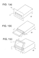
- FIGS. 1(a) to 1(c) are external perspective views showing the construction and operations of an in-dash monitor according to the embodiment.
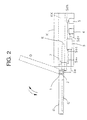
- FIG. 2 is a side view showing the internal construction and operations of the in-dash monitor of the embodiment.
- FIG. 3 shows a block diagram outlining the electric configuration of a video display apparatus according to the present invention, while FIGS. 4 and 5 show flowcharts of processing for display control performed by the video displaying apparatus.
- the in-dash monitor IM of the present embodiment includes a display panel D serving as a display device and a receiver K serving as a receiving device.
- the display panel D is received in the receiver K, as shown in FIG. 1(a).
- the receiver K is mounted within a dashboard DB such that only the front thereof, including the front of the display panel D, is exposed to the interior space of the automobile.
- the display panel D be extended or unfolded.
- the display panel D and an axis J for rotating the display panel D are drawn forward from the receiver K with a drawing rail R sliding on a guide of the receiver (refer to a solid-line arrow in FIG. 1(b)).
- the display panel D After completely drawing the axis J and display panel D out of the receiver K, the display panel D is turned clockwise (in FIG. 1(c)) around the axis J, as illustrated by a solid-line arrow in FIG. 1(c). This action enables the display panel D to stand up, so that a display screen mounted on one side of the display panel D is located so as to face to a crew. Accordingly, a crew is allowed to have access to the display panel D.
- the foregoing actions can be performed by driving a motor for sliding the display panel D and axis J along the drawing rail R and a motor for rotating the display panel D about the axis J, both motors being described later.
- the in-dash monitor IM of the present embodiment comprises the foregoing display panel D, made up of a liquid crystal panel or others, having on its one side a display screen G for displaying desired images, and a receiver K having therein a receiving space KK in which the display panel D is received horizontally in FIG.2 when the monitor is not used.
- the receiver K is mounted in the dashboard DB with its front opened outside, as shown in FIG. 1.
- the display panel D is placed with the axis J in such a manner that the panel is rotatable about the axis J.
- the display panel D When being unused, the display panel D is pulled into and received in the receiving space KK together with the axis J.
- the panel is pulled out from the receiving space KK together with the axis J toward the left in FIG. 2, before it is rotated clockwise in FIG. 2 up to a stop position shown by a dotted line in FIG. 2, thus realizing a stand-up state of the panel at rest at the stop position.
- the display panel D is rotated counterclockwise in FIG. 2 from the dotted line position shown in FIG. 2 to a position, which is shown by a solid line in FIG. 2, allowing the panel to be ready for being received in the receiving space KK.
- the display panel is then pulled into the receiver K together with the axis J toward the right in FIG. 2, which completes the receiving of the panel.
- the solid-lined panel position in FIG. 2 functions as a position for allowing the display panel D to be thoroughly received in the receiving space KK (without collisions of the panel to the inner walls of the receiving space KK during travel of the panel in the receiving space).
- the solid-lined panel position in FIG. 2 is referred to as a "receiving position.”
- Both of the display panel D and the axis J are moved together along the drawing rail R movable in the right and left direction in FIG. 2 so that they are pulled out of or inserted in the receiving space KK.
- An encoder 1 which functions as a detection device, is coaxially attached to the axis J.
- the encoder 1 generates a position detecting signal Se indicative of voltage approximately proportional to a rotational angle of the display panel D and sends it to a microcomputer 3 described later.
- a lead-in switch 2 On an end of the display panel D is secured a lead-in switch 2 that come into its on state responsively to a touch with the inner wall of the receiving space KK in cases the display panel D is completely inserted into the receiving space KK.
- the lead-in switch 2 generates a lead-in signal Ssc in response to its on state and sends it to the microcomputer 3.
- a rotary motor driver 4 and a slider motor driver 5 In other portions other than the receiving space KK in the receiver K, there are secured a rotary motor driver 4 and a slider motor driver 5.
- Each of the drivers 4 and 5 is controlled with each of control signals Sdr and Sdh supplied from the microcomputer 3, thereby driving a rotary motor and a slider motor, respectively.
- the microcomputer 3 which serves as one element for a detection device and a receiving control device, realizes control with an output controller 6 described later and executes later-described processing by using both of the position detecting signal Se from the encoder 1 and the lead-in signal Ssc from the switch 2.
- the microcomputer 3 controls exposing action, retracting action, and other actions of the display panel D as well as outputs a video signal Sav to the display panel D through later-described processing.
- video expressed by the video signal Sav can be visualized on a display screen G of the display panel D.
- the exposure of the display panel D is defined by a series of actions of drawing the display D out of the receiver K together with the axis J, and then rotating the drawn display panel in the clockwise in FIG. 2 up to an angular position providing a video displayable state.
- the video displayable state is a state in which video on the display screen G is clearly visible for users.
- the receiving of the display panel D is defined by a series of actions of rotating back the display panel D under the video displayable state down to an angular position for receiving in the counterclockwise in FIG. 2, and then inserting the panel in the receiver K completely.
- the video displayable state is realized in such a manner that, for example, a user previously operates an operation device so as to provide the microcomputer 3 with angular information which allows the display panel D to stand at a desired easy-to-see angle.
- the configuration and outlined operations of the video display apparatus according to the present embodiment will now be described, which includes the in-dash monitor IM constructed and operated as above.
- a video display apparatus S including the foregoing in-dash monitor IM comprises (i) an output controller 6 functioning as an output device, (ii) an operation device 7 and (iii) a video output unit 8.
- the video output unit 8 produces the video signal Sav of video to be displayed on the display panel D, and sends it to the output controller 6.
- an information replay apparatus serves as the video output unit 8, in which the recorded information is detected from the optical disc to replay it as video. Further, for displaying on the display panel D video received through a radio wave of television broadcasting, the video output unit 8 is realized by a television receiver to receive the broadcasting radio wave.
- the output controller 6 controls the microcomputer 3 of the in-dash monitor IM based on an operation signal Sin supplied responsively to an operation performed with the operation device 7. This makes the display panel D display necessary video thereon.
- the output controller 6 provides the microcomputer 3 with the video signal Sav that has been sent from the video output unit 8 and a synchronization signal Ssy for the video signal Sav.
- the synchronization signal Ssy which composes part of the video signal Sav, is given to the microcomputer 3 prior to transmitting video expressed by the video signal Sav to the microcomputer 3.
- the output controller 6 executes display control processing shown in FIG. 5 on the basis of a pose signal Spz, an exposure completion signal Sop, and an under-exposure signal Scp, which will be described later, all of which are supplied from the microcomputer 3.
- the microcomputer 3 performs later-described processing based on the position detecting signal Se, with the result that the pose signal Spz, the exposure completion signal Sop, and the under-exposure signal Scp are produced to be sent to the output controller 6.
- the pose signal Spz is a signal for temporarily causing the output controller 6 to stop outputting the video signal Sav.
- the exposure completion signal Sop shows that the exposure of the display panel D to the video displayable state has been completed.
- the under-exposure signal Scp shows that the display panel D is now under development to the video displayable state.
- the microcomputer 3 execute display control processing shown in FIG. 4.
- the foregoing control signals Sdr and Sdh are sent to the rotary motor driver 4 and slider motor driver 5, respectively, and the video signal Sav is sent to the display panel D.
- Step S1 it is first determined whether or not the synchronization signal Ssy, which precedes the video signal Sav, has been received.
- Step S1 When it is determined that the synchronization signal Ssy has been received (YES at Step S1), the processing transfers to a step to display on the display panel D video corresponding to the video signal Sav which should be received next. It is then determined if the display panel D is now extended or unfolded in the video displayable state or received in the receiver K, based on the lead-in signal Ssc and position detecting signal Se (Step S2).
- Step S2 If the display panel D is extended up to a position for the video displayable state (NO at Step S2), it is recognized that the video can be displayed at once, thus being moved to processing at Step S7.
- the microcomputer 3 produces the pose signal Spz to output it to the output controller 6 (Step S3), thus realizing a temporal stop of output of the video signal Sav.
- the microcomputer 3 also produces the foregoing control signals Sdh and Sdr and then outputs their control signals to the slider motor driver 5 and the rotary motor driver 4, respectively (Step S4), pulling out the display panel D from the receiver and placing it up to the position for the video displayable state.
- Step S5 When the exposure of the display panel D starts, it is determined based on the position detecting signal Se whether or not the display panel D has been placed in the position for the video displayable state (Step S5). If the exposure is not completed (NO at Step S5), the under-exposure signal Scp is outputted to the output controller 6 to continue the exposure processing (Step S6).
- Step S5 when it is detected at the determination of Step S5 that the exposure of the display panel D has been completed (YES at Step S5), the exposure completion signal Sop is produced and sent to the output controller 6 (Step S7).
- Step S8 It is then determined whether or not a video signal Sav including video information to be displayed has been received from the output controller 6 (Step S8). If the video signal Say has not been received (NO at Step S8), the processing to monitor the reception is repeated. In contrast, the video signal Sav has been received (YES at Step 8), the video is displayed on the display panel D that has already been in the video displayable state (Step S9).
- Step S10 the determination that the display has been completed is made for all pieces of video.
- the display processing for other pieces of video is continued, while when the display has been completed (YES at Step S10), the display control processing is finished for all the pieces of video.
- the display panel D will be received in the receiver K.
- Step S1 it is determined at Step S1 that the synchronization signal Ssy has not been received (NO at Step S1), it is recognized that video to be displayed has not been obtained. Then, it is determined if or not a specified period of time has passed with no reception of the synchronization signal Ssy (Step S11). The processing at Step S11 determines if the synchronization signal Ssy has not been received yet or not, that is, video to be displayed has not been received yet or not.
- Step S11 In cases it is determined at step S11 that the specified period of time has not passed (NO at Step S11), waiting for the synchronization signal Ssy is done until the specified period of time passes. On the other hand, when the specified period of time has passed (YES at Step S11), it is determined on the basis of the position detecting signal Se whether or not the display panel D is currently in the video displayable state (Step S12).
- the display control processing is terminated without any actions.
- the display panel D is in the video displayable state (YES at Step S12)
- the display panel D currently in the video displayable state is forced to be received in the receiver K (Step S13), before the display control processing is terminated.
- the output controller 6 determines if or not an operation signal Sin has been received from the operation device 7 (Step S15), the signal indicating that video should be read from the video output unit 8 to display it on the display panel D.
- an operation signal Sin has not been inputted (NO at Step S15)
- waiting is kept until the input of the operation signal.
- the synchronization signal Ssy included in the video signal Sav provided from the video output unit 8 is sent to the microcomputer 3 prior to the video itself (Step S16: refer to Step S1 in FIG. 4).
- Step S17 It is then determined whether or not the pose signal Spz has been received from the microcomputer 3 (Step S17). In the case that the pose signal has not been received (NO at Step S17), waiting is kept during a specified period of time without any processing.
- the display control processing is obliged to be terminated (Step S23), because it is considered that there occurs a malfunction in exposing the display monitor D.
- Step S17 when it is determine that the pose signal Spz has been received (YES at Step S17), it is recognized that the display panel D has not been ready for its video displayable state in the in-dash monitor IM yet. Thus, the output of the video signal (video information) Sav to the microcomputer 3, which follows the synchronization signal Ssy, is halted temporarily (Step S18). It is then determined whether or not the under-exposure signal Scp (refer to Step S6 in FIG.4) has been received (Step S19).
- Step S19 When the reception of the under-exposure signal Scp is determined at Step 19 (YES at Step S19), it is recognized that the display panel D has been yet to be extended or unfolded up to its video displayable state in the in-dash monitor IM, thereby its temporarily halted state is maintained (Step S18). On the other hand, when the under-exposure signal Scp has not been received yet (NO at Step S19), it is then determined if the exposure completion signal Sop (refer to Step S7 in FIG. 4) has been received or not (Step S20).
- Step S18 If the exposure completion signal Sop has not been received yet (NO at Step S20), it is recognized that the display panel D has been yet to be extended up to its video displayable state in the in-dash monitor IM, thereby its temporarily halted state is maintained (Step S18). In contrast, when the exposure completion signal Sop has been received (YES at Step S20), it is recognized that the exposure of the display panel D in the in-dash monitor IM has been completed.
- the output of the video signal (video information) Sav which has been temporarily halted at Step S18, is started to display the video on the display panel D (Step S21: refer to Steps S8 and S9 in FIG. 4).
- Step S22 It is then determined if the output of all pieces of video to the microcomputer 3 has been completed or not (Step S22). When such completion is not realized (NO at Step S22), the output of the video signal Sav for the remaining pieces of video is repeated (Step S21). In contrast, when being completed (YES at Step S22), the entire display control processing is terminated.
- the display of video is started only when the display panel D comes into its video displayable state (refer to Step S21 in FIG.5). In other words, all pieces of video to be displayed can be displayed on the display panel D brought into its video displayable state in advance.
- the video signal Sav is prohibited from being outputted (temporarily halted) to the display panel D (refer to Step S18 in FIG.5). This prohibition makes it possible to avoid video from being displayed in the course of exposing the display panel D.
- Step S1 in FIG.4 the display panel D is retracted from its video displayable state. It is therefore possible to retract the display panel D without any user's manual operation.
- the position to which the display panel D is unfolded provides its video displayable state in which the video is clearly visible. This prevents video from being displayed with an improper visible state.
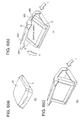
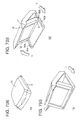
- FIGS. 6(a)-6(c) to 9(a)-9(b) are external perspective views each showing a video display apparatus of each modification.
- the foregoing embodiment has explained the video display control processing, which is executed in the in-dash monitor performing the operations as shown in FIG. 1, to which the present invention is applied. Moreover, the present invention is not limited to such a mode, but can be applied to various other modes of video display apparatus.
- a video display apparatus H1 for example, as shown in FIGS. 6(a) to 6(c), there is provided a video display apparatus H1 according to the first modification.
- the video display apparatus H1 has a construction in which a front cover 10 is folded onto a base 11 with a liquid crystal monitor 12 received therebetween. A not-shown attachment to secure the base 11 on a dashboard or others is secured on the base 11.
- protrusions 18A and 18B secured on both upper corners of the liquid crystal monitor 12 come into engagement with the guide grooves 16A and 16B.
- a user grasps a holding end 13 or others of the front cover 10, and can open and close the front cover 10.
- the protrusions 18A and 18B are smoothly slid along the guide grooves 16A and 16B about a pivot shaft (a hinge) 17.
- a not-shown stopping mechanism is secured closely to the pivot shaft 17, so that the liquid crystal monitor can be stopped at a prescribed angular position.
- this video display apparatus H1 is opened by hand, the holding end 13 of the front cover 10 is grasped by fingertips and opened, as being pushed slightly, in a direction X in FIG. 6(b).
- the liquid crystal 12 In association with a motion of the front cover 10, the liquid crystal 12 gradually stands up as it slides along the guide grooves 16A and 16B, as shown in directions Y and Z.
- a not-shown chuck device locks the monitor 12.
- the chuck device is released to fold the liquid crystal 12 between the front cover 10 and the base 11.
- the output of the signals are controlled as follows. That is, the pose signal Spz and under-exposure signal Scp are outputted from the microcomputer 3 during placing the liquid crystal monitor 12 in a position shown in FIG. 6(c). In addition, the exposure completion signal Sop is outputted to start the output of the video signal Sav, when the liquid crystal monitor 12 has been extended or unfolded up to a video displayable position.
- the video display apparatus H1 of the present modification arranging electric motors or other necessary devices closely to the pivot shaft 17 enables the video display apparatus to be opened and closed with electric power. In this case, the determination whether or not the synchronization signal Ssy is received within a specified period of time is made. If the determination of no reception is made, i.e., the display of video is completed, the video display apparatus H1 currently under its opened state is closed.
- the second modification will now be described.
- the video display apparatus H2 has a construction in which a front cover 10 is foldable onto a base 11 with a liquid crystal monitor 12 received therebetween. A not-shown attachment to secure the base 11 on a dashboard or others is secured on the base 11.
- protrusions 18A and 18B secured on both lower corners of the liquid crystal monitor 12 come into engagement with the guide grooves 16A and 16B.
- a user grasps a holding end 13 or others of the front cover 10, and can open or close the front cover 10. In association with the open or close motion of the front cover 10, the protrusions 18A and 18B are smoothly slid along the guide grooves 16A and 16B about a pivot shaft 17.
- a not-shown stopping mechanism is secured closely to the pivot shaft 17, so that the liquid crystal monitor can be stopped at a prescribed angular position.
- this video display apparatus H2 is opened by hand, the holding end 13 of the front cover 10 is grasped by fingertips and opened, as being pushed slightly, in a direction X in FIG. 6(b).
- the liquid crystal 12 In association with a motion of the front cover 10, the liquid crystal 12 gradually gets up as it slides along the guide grooves 16A and 16B, as shown in a direction Y.
- a not-shown chuck device locks the monitor 12.
- the chuck device is released to fold the liquid crystal 12 between the front cover 10 and the base 11.
- the output of the signals are controlled as follows. That is, the pose signal Spz and under-exposure signal Scp are outputted from the microcomputer 3 during exposing the liquid crystal monitor 12 in a position shown in FIG. 7(c). In addition, the exposure completion signal Sop is outputted to start the output of the video signal Sav, when the liquid crystal monitor 12 has been unfolded up to a video displayable position.
- the video display apparatus H2 of the present modification arranging electric motors or other necessary devices closely to the spindle 17 enables the video display apparatus to be opened or closed with electric power. In this case, the determination whether or not the synchronization signal Ssy is received within a prescribed period of time is made. If the determination of no reception is made, i.e., the display of video is completed, the video display apparatus H2 currently under its opened state is closed.
- a video display apparatus H3 according to the third modification will now be described.
- a front cover 10 and a base 11 are coupled with each other with the front cover 10 rotatable freely.
- An attachment 19 for securing the base 11 on a dashboard or others is attached to the base 11.
- the attachment 19 is secured on the dashboard using a double-coated adhesive tape 19A and/or screws 19B.
- guide grooves 16A and 16B are formed. Protrusions 18A and 18B secured on both lower corners of the front cover 10 come into engagement with the guide grooves 16A and 16B. A user grasps a holding end 13 or others of the front cover 10, and can open and close the front cover 10. In association with the open and close motions of the front cover 10, the protrusions 18A and 18B are smoothly slid along the guide grooves 16A and 16B.
- a not-shown stopping mechanism allows the liquid crystal monitor to be stopped at a prescribed angular position.
- the holding end 13 of the front cover is grasped by fingertips and opened with a push in a direction X as the holding end is slightly moved forward.
- the front cover 10 is then pushed down in a direction Y in such a manner that the protrusions 18A and 18B are smoothly slid forward along the guide grooves 16A and 16B.
- FIG. 8(d) exemplifies the pivot shaft and a rotation angle of the front cover 10.
- the front cover 10 can be closed through folding.
- the video display apparatus H3 of the present modification can electrically be opened and closed by an electric motor. In this case, the determination whether or not the synchronization signal Ssy is received within a specified period of time is made. If the determination of no reception is made, i.e., the display of video is completed, the video display apparatus H3 currently under its opened state is closed.
- the output of the signals are controlled as follows. That is, the pose signal Spz and under-exposure signal Scp are outputted from the microcomputer 3 during placing the liquid crystal monitor 12 in a position shown in FIG. 8(d).
- the exposure completion signal Sop is outputted to start the output of the video signal Sav, when the liquid crystal monitor 12 has been extended up to a video displayable position.
- the video display apparatus H4 has a base 11 on which a liquid crystal monitor 12 is integrally formed together with a not-shown attachment for securing the base on a dashboard or others.
- a reflecting mirror 20 is mounted on the inner surface of a front cover 10.
- front cover 10 is rotatably coupled with the base 11 via a pivot shaft 17, providing a folding structure in which the front cover 10 can be smoothly turned upward or downward.
- a not-shown stopping mechanism arranged closely to the pivot shaft 17 is used for stopping the front cover 10 at a prescribed angular position.
- the front cover 10 is stopped by the stopping mechanism at a prescribed angular position.
- the front cover 10 which is now opened, can be closed by hand or with an electrical power device.
- This construction gives users an optimum angle of field of view for use, thus providing the video display apparatus H4 capable of securing safety and a forward view of uses for non-use.
- the output of the signals are controlled as follows. That is, the pose signal Spz and under-exposure signal Scp are outputted from the microcomputer 3 during placing the front cover 10 in a position shown in FIG.9B.
- the exposure completion signal Sop is outputted to start the output of the video signal Sav, when the front cover 10 has been unfolded up to an angular position shown in FIG.9B.
- the front cover 10 In cases the front cover 10 is electrically powered for its closing, it is determined if the synchronization signal Ssy has been received or not during a prescribed period of time. When there is no reception of such signal, i.e., the display of video is completed, the front cover 10 is closed.
- a personal computer can be used for the microcomputer 3 and output controller 6, as long as programs of the flowcharts shown in FIGS. 4 and 5 are stored in a flexible disc, a hard disc, or others serving as an information medium and the personal computer is able to read the programs for execution.
Landscapes
- Engineering & Computer Science (AREA)
- Mechanical Engineering (AREA)
- Devices For Indicating Variable Information By Combining Individual Elements (AREA)
- Fittings On The Vehicle Exterior For Carrying Loads, And Devices For Holding Or Mounting Articles (AREA)
- Controls And Circuits For Display Device (AREA)
Applications Claiming Priority (2)
| Application Number | Priority Date | Filing Date | Title |
|---|---|---|---|
| JP2000242296A JP2002055625A (ja) | 2000-08-10 | 2000-08-10 | 表示制御装置、表示制御方法及び情報記録媒体 |
| JP2000242296 | 2000-08-10 |
Publications (3)
| Publication Number | Publication Date |
|---|---|
| EP1179450A2 true EP1179450A2 (de) | 2002-02-13 |
| EP1179450A3 EP1179450A3 (de) | 2003-02-05 |
| EP1179450B1 EP1179450B1 (de) | 2005-09-28 |
Family
ID=18733335
Family Applications (1)
| Application Number | Title | Priority Date | Filing Date |
|---|---|---|---|
| EP01306458A Expired - Lifetime EP1179450B1 (de) | 2000-08-10 | 2001-07-27 | Anzeigesteuereinheit, Anzeigesteuerverfahren und Informationsaufzeichnungsmedium |
Country Status (4)
| Country | Link |
|---|---|
| US (1) | US7133085B2 (de) |
| EP (1) | EP1179450B1 (de) |
| JP (1) | JP2002055625A (de) |
| DE (1) | DE60113615T2 (de) |
Cited By (7)
| Publication number | Priority date | Publication date | Assignee | Title |
|---|---|---|---|---|
| GB2392882A (en) * | 2002-09-12 | 2004-03-17 | Sealine Internat Ltd | A boat having a concealed display device |
| EP1367580A3 (de) * | 2002-05-30 | 2004-09-15 | Pioneer Corporation | Wiedergabeanzeigegerät und Wiedergabeanzeigeverfahren |
| GB2414131A (en) * | 2004-05-12 | 2005-11-16 | E Lead Electronic Co Ltd | Foldable multimedia display apparatus |
| WO2007031453A3 (de) * | 2005-09-12 | 2007-10-11 | Siemens Ag | Anzeigesystem mit einer anzeige, die zwischen einer ruhe- und einer betriebsposition bewegbar ist |
| DE102007004446A1 (de) * | 2007-01-30 | 2008-07-31 | Audi Ag | Armaturenfach eines Fahrzeugs für einen mobilen Computer |
| FR2929202A1 (fr) * | 2008-03-31 | 2009-10-02 | Vision Systems Aeronautics Soc | Dispositif de diffusion d'information visuelle ou de contenu audiovisuel. |
| CN112092740A (zh) * | 2020-09-22 | 2020-12-18 | 广州鹰瞰信息科技有限公司 | 一种车载导航设备 |
Families Citing this family (24)
| Publication number | Priority date | Publication date | Assignee | Title |
|---|---|---|---|---|
| CN1701349A (zh) * | 2003-03-19 | 2005-11-23 | 松下电器产业株式会社 | 显示设备 |
| US7663706B2 (en) * | 2004-06-03 | 2010-02-16 | Costel Co., Ltd. | In-wall type multi-functional television set |
| US8230096B2 (en) * | 2005-01-14 | 2012-07-24 | Citrix Systems, Inc. | Methods and systems for generating playback instructions for playback of a recorded computer session |
| US8935316B2 (en) | 2005-01-14 | 2015-01-13 | Citrix Systems, Inc. | Methods and systems for in-session playback on a local machine of remotely-stored and real time presentation layer protocol data |
| US8200828B2 (en) | 2005-01-14 | 2012-06-12 | Citrix Systems, Inc. | Systems and methods for single stack shadowing |
| US8296441B2 (en) | 2005-01-14 | 2012-10-23 | Citrix Systems, Inc. | Methods and systems for joining a real-time session of presentation layer protocol data |
| US20060159432A1 (en) | 2005-01-14 | 2006-07-20 | Citrix Systems, Inc. | System and methods for automatic time-warped playback in rendering a recorded computer session |
| DE102007011521A1 (de) * | 2007-03-09 | 2008-07-10 | Audi Ag | Vorrichtung zur Halterung von Gegenständen |
| US20110025943A1 (en) * | 2008-05-27 | 2011-02-03 | Sharp Kabushiki Kaisha | Display device |
| JP2010036659A (ja) * | 2008-08-01 | 2010-02-18 | Pioneer Electronic Corp | ディスプレイ装置 |
| JP2010042694A (ja) * | 2008-08-08 | 2010-02-25 | Pioneer Electronic Corp | ディスプレイ装置の動力伝達機構 |
| WO2010021044A1 (ja) * | 2008-08-21 | 2010-02-25 | パイオニア株式会社 | 車載用機器の衝撃吸収構造 |
| JP2010070125A (ja) * | 2008-09-19 | 2010-04-02 | Pioneer Electronic Corp | ディスプレイ装置、駆動制御方法 |
| JP2010070122A (ja) * | 2008-09-19 | 2010-04-02 | Pioneer Electronic Corp | ディスプレイ装置、駆動制御方法 |
| JP5241398B2 (ja) * | 2008-09-19 | 2013-07-17 | パイオニア株式会社 | ディスプレイ装置、駆動制御方法 |
| JP5198997B2 (ja) * | 2008-09-19 | 2013-05-15 | パイオニア株式会社 | ディスプレイ装置、駆動制御方法 |
| US8070120B2 (en) * | 2008-11-19 | 2011-12-06 | Hoffman Enclosures, Inc. | Vertical motion pendant arm |
| CN101751083A (zh) * | 2008-12-01 | 2010-06-23 | 鸿富锦精密工业(深圳)有限公司 | 电子设备组件及其支架 |
| US8615159B2 (en) | 2011-09-20 | 2013-12-24 | Citrix Systems, Inc. | Methods and systems for cataloging text in a recorded session |
| CN107105181B (zh) * | 2017-05-24 | 2020-06-19 | 赣州市牧士电子有限公司 | 一种多功能电视 |
| CN107972596A (zh) * | 2017-11-14 | 2018-05-01 | 北京汽车股份有限公司 | 用于车辆的仪表板和具有它的车辆 |
| RU187297U1 (ru) * | 2018-11-06 | 2019-02-28 | Российская Федерация, от имени которой выступает Министерство обороны Российской Федерации | Устройство подъема-опускания средства отображения информации |
| WO2023277910A1 (en) * | 2021-06-30 | 2023-01-05 | Hewlett-Packard Development Company, L.P. | Retractable displays for electronic meetings |
| US11946781B2 (en) * | 2022-01-25 | 2024-04-02 | Hewlett-Packard Development Company, L.P. | Sensor assemblies coupled to sliding assemblies for position sensing |
Family Cites Families (22)
| Publication number | Priority date | Publication date | Assignee | Title |
|---|---|---|---|---|
| JPH0231577A (ja) * | 1988-07-20 | 1990-02-01 | Alpine Electron Inc | デイスプレイ装置 |
| US5161028A (en) * | 1989-07-20 | 1992-11-03 | Kabushiki Kaisha Toshiba | Car-mounted video displaying apparatus |
| US5847685A (en) * | 1992-08-19 | 1998-12-08 | Alpine Electronics, Inc. | Vehicle-mounted display mechanism |
| EP0614104A3 (de) * | 1993-03-05 | 1995-12-20 | Hughes Aircraft Co | System zur Steuerung von virtuellen Bildanzeigen mit "head-up" Anzeigesystem. |
| US5742358A (en) * | 1994-05-12 | 1998-04-21 | Casio Computer Co., Ltd. | Projection type displaying apparatus having screen |
| US5555466A (en) * | 1994-10-12 | 1996-09-10 | Asa Electronics Corporation | Vehicular audio/visual system having distribution box for connecting individual passenger monitors to multiple program sources |
| JPH09325710A (ja) * | 1996-06-04 | 1997-12-16 | Tokai Rika Co Ltd | 収納式ディスプレイ装置 |
| US5946055A (en) * | 1996-08-16 | 1999-08-31 | Rosen Product Development, Inc. | Display unit |
| GB9722934D0 (en) * | 1996-12-31 | 1998-01-07 | John B Rosen | Personal video system |
| GB2322105B (en) * | 1997-02-06 | 1999-08-18 | Nissan Motor | Vehicle display layout structure |
| US5811791A (en) * | 1997-03-25 | 1998-09-22 | Sony Corporation | Method and apparatus for providing a vehicle entertainment control system having an override control switch |
| US5949345A (en) * | 1997-05-27 | 1999-09-07 | Microsoft Corporation | Displaying computer information to a driver of a vehicle |
| US5996954A (en) * | 1997-10-14 | 1999-12-07 | Rosen Products Llc | Stowable support apparatus |
| JP3259954B2 (ja) * | 1997-12-18 | 2002-02-25 | 株式会社オートネットワーク技術研究所 | 車載用ユニット |
| US6125030A (en) * | 1998-08-07 | 2000-09-26 | Lear Donnelly Overhead Systems L.L.C. | Vehicle overhead console with flip down navigation unit |
| DE10029612A1 (de) * | 1999-07-14 | 2001-01-18 | Volkswagen Ag | Anzeige- und/oder Bedieneinrichtung für mindestens eine elektrische Einrichtung in Kraftfahrzeugen |
| US6816129B1 (en) * | 1999-12-21 | 2004-11-09 | International Business Machines Corporation | Multiple display device for use with existing personal computer systems |
| US6633658B1 (en) * | 2000-03-17 | 2003-10-14 | Senorx, Inc. | System and method for managing intermittent interference on imaging systems |
| US6778381B1 (en) * | 2000-10-18 | 2004-08-17 | Hewlett-Packard Development Company, L.P. | Retractable display module |
| US6678892B1 (en) * | 2000-10-27 | 2004-01-13 | Audivox Corporation | Multimedia entertainment unit for use in a vehicle |
| US6409242B1 (en) * | 2000-11-14 | 2002-06-25 | Chung L. Chang | Flat thin screen T/V monitor automotive roof mount |
| US6443574B1 (en) * | 2001-07-24 | 2002-09-03 | Visteon Global Technologies, Inc. | Removable vehicle entertainment system |
-
2000
- 2000-08-10 JP JP2000242296A patent/JP2002055625A/ja not_active Abandoned
-
2001
- 2001-07-27 EP EP01306458A patent/EP1179450B1/de not_active Expired - Lifetime
- 2001-07-27 DE DE60113615T patent/DE60113615T2/de not_active Expired - Fee Related
- 2001-08-08 US US09/924,055 patent/US7133085B2/en not_active Expired - Fee Related
Non-Patent Citations (1)
| Title |
|---|
| None |
Cited By (11)
| Publication number | Priority date | Publication date | Assignee | Title |
|---|---|---|---|---|
| EP1367580A3 (de) * | 2002-05-30 | 2004-09-15 | Pioneer Corporation | Wiedergabeanzeigegerät und Wiedergabeanzeigeverfahren |
| GB2392882A (en) * | 2002-09-12 | 2004-03-17 | Sealine Internat Ltd | A boat having a concealed display device |
| GB2414131A (en) * | 2004-05-12 | 2005-11-16 | E Lead Electronic Co Ltd | Foldable multimedia display apparatus |
| GB2414131B (en) * | 2004-05-12 | 2006-04-26 | E Lead Electronic Co Ltd | Foldable multimedia display apparatus |
| WO2007031453A3 (de) * | 2005-09-12 | 2007-10-11 | Siemens Ag | Anzeigesystem mit einer anzeige, die zwischen einer ruhe- und einer betriebsposition bewegbar ist |
| CN101263029B (zh) * | 2005-09-12 | 2011-01-26 | 大陆汽车有限责任公司 | 具有可在停止位置与运行位置之间移动的显示装置的显示系统 |
| DE102007004446A1 (de) * | 2007-01-30 | 2008-07-31 | Audi Ag | Armaturenfach eines Fahrzeugs für einen mobilen Computer |
| DE102007004446B4 (de) * | 2007-01-30 | 2010-12-16 | Audi Ag | Armaturenfach eines Fahrzeugs für einen mobilen Computer |
| FR2929202A1 (fr) * | 2008-03-31 | 2009-10-02 | Vision Systems Aeronautics Soc | Dispositif de diffusion d'information visuelle ou de contenu audiovisuel. |
| CN112092740A (zh) * | 2020-09-22 | 2020-12-18 | 广州鹰瞰信息科技有限公司 | 一种车载导航设备 |
| CN112092740B (zh) * | 2020-09-22 | 2021-04-06 | 广州鹰瞰信息科技有限公司 | 一种车载导航设备 |
Also Published As
| Publication number | Publication date |
|---|---|
| EP1179450B1 (de) | 2005-09-28 |
| DE60113615T2 (de) | 2006-06-22 |
| US7133085B2 (en) | 2006-11-07 |
| EP1179450A3 (de) | 2003-02-05 |
| US20020051098A1 (en) | 2002-05-02 |
| DE60113615D1 (de) | 2005-11-03 |
| JP2002055625A (ja) | 2002-02-20 |
Similar Documents
| Publication | Publication Date | Title |
|---|---|---|
| EP1179450B1 (de) | Anzeigesteuereinheit, Anzeigesteuerverfahren und Informationsaufzeichnungsmedium | |
| JPH09224202A (ja) | 折り畳み表示装置 | |
| US20010049960A1 (en) | Apparatus for controlling an electronic equipment for vehicles | |
| JP2014143850A (ja) | ヘッドアップディスプレイ装置 | |
| JP3039719B2 (ja) | 車載用テレビ | |
| JPH07159193A (ja) | 表示装置 | |
| CN117141382B (zh) | 遮阳板系统及车辆 | |
| JP3233427B2 (ja) | 車載用テレビ | |
| JP2804643B2 (ja) | 車載用ディスプレイ装置 | |
| JPH0495543A (ja) | 車載テレビ格納装置 | |
| JP3718972B2 (ja) | 開閉式反射型表示装置 | |
| CN117183905A (zh) | 汽车用投影系统及汽车 | |
| JP3215140B2 (ja) | 車載用テレビ | |
| JP2000309247A (ja) | 車載用インダッシュモニター | |
| JP2003237484A (ja) | 車載用電子機器 | |
| JP2010032316A (ja) | 表示手段制御装置及び表示手段制御方法並びに表示手段制御用プログラム | |
| JP4184629B2 (ja) | 車載用ディスプレイ装置 | |
| JPH10309996A (ja) | 表示装置 | |
| JPH0646493B2 (ja) | 操作パネル開閉機能付き電子機器 | |
| JP3089096B2 (ja) | 車載用ディスプレイ装置 | |
| JP2002204409A (ja) | 車載用av装置の保持機構 | |
| JPH05185876A (ja) | 車載用テレビ | |
| JP2003068062A (ja) | 電子機器 | |
| JP2000105990A (ja) | 車載機器の可動ノーズ制御装置 | |
| JPH10117310A (ja) | 車載用収容型モニタ |
Legal Events
| Date | Code | Title | Description |
|---|---|---|---|
| PUAI | Public reference made under article 153(3) epc to a published international application that has entered the european phase |
Free format text: ORIGINAL CODE: 0009012 |
|
| AK | Designated contracting states |
Kind code of ref document: A2 Designated state(s): AT BE CH CY DE DK ES FI FR GB GR IE IT LI LU MC NL PT SE TR |
|
| AX | Request for extension of the european patent |
Free format text: AL;LT;LV;MK;RO;SI |
|
| PUAL | Search report despatched |
Free format text: ORIGINAL CODE: 0009013 |
|
| AK | Designated contracting states |
Designated state(s): AT BE CH CY DE DK ES FI FR GB GR IE IT LI LU MC NL PT SE TR |
|
| AX | Request for extension of the european patent |
Extension state: AL LT LV MK RO SI |
|
| 17P | Request for examination filed |
Effective date: 20030801 |
|
| AKX | Designation fees paid |
Designated state(s): DE FR GB |
|
| 17Q | First examination report despatched |
Effective date: 20040614 |
|
| GRAP | Despatch of communication of intention to grant a patent |
Free format text: ORIGINAL CODE: EPIDOSNIGR1 |
|
| GRAS | Grant fee paid |
Free format text: ORIGINAL CODE: EPIDOSNIGR3 |
|
| GRAA | (expected) grant |
Free format text: ORIGINAL CODE: 0009210 |
|
| AK | Designated contracting states |
Kind code of ref document: B1 Designated state(s): DE FR GB |
|
| REG | Reference to a national code |
Ref country code: GB Ref legal event code: FG4D |
|
| REF | Corresponds to: |
Ref document number: 60113615 Country of ref document: DE Date of ref document: 20051103 Kind code of ref document: P |
|
| ET | Fr: translation filed | ||
| REG | Reference to a national code |
Ref country code: GB Ref legal event code: 746 Effective date: 20060612 |
|
| PLBE | No opposition filed within time limit |
Free format text: ORIGINAL CODE: 0009261 |
|
| STAA | Information on the status of an ep patent application or granted ep patent |
Free format text: STATUS: NO OPPOSITION FILED WITHIN TIME LIMIT |
|
| 26N | No opposition filed |
Effective date: 20060629 |
|
| PGFP | Annual fee paid to national office [announced via postgrant information from national office to epo] |
Ref country code: DE Payment date: 20070719 Year of fee payment: 7 |
|
| PGFP | Annual fee paid to national office [announced via postgrant information from national office to epo] |
Ref country code: GB Payment date: 20070725 Year of fee payment: 7 |
|
| PGFP | Annual fee paid to national office [announced via postgrant information from national office to epo] |
Ref country code: FR Payment date: 20070710 Year of fee payment: 7 |
|
| GBPC | Gb: european patent ceased through non-payment of renewal fee |
Effective date: 20080727 |
|
| PG25 | Lapsed in a contracting state [announced via postgrant information from national office to epo] |
Ref country code: DE Free format text: LAPSE BECAUSE OF NON-PAYMENT OF DUE FEES Effective date: 20090203 |
|
| REG | Reference to a national code |
Ref country code: FR Ref legal event code: ST Effective date: 20090331 |
|
| PG25 | Lapsed in a contracting state [announced via postgrant information from national office to epo] |
Ref country code: GB Free format text: LAPSE BECAUSE OF NON-PAYMENT OF DUE FEES Effective date: 20080727 |
|
| PG25 | Lapsed in a contracting state [announced via postgrant information from national office to epo] |
Ref country code: FR Free format text: LAPSE BECAUSE OF NON-PAYMENT OF DUE FEES Effective date: 20080731 |