EP1179657A1 - Distribution variable - Google Patents
Distribution variable Download PDFInfo
- Publication number
- EP1179657A1 EP1179657A1 EP01000338A EP01000338A EP1179657A1 EP 1179657 A1 EP1179657 A1 EP 1179657A1 EP 01000338 A EP01000338 A EP 01000338A EP 01000338 A EP01000338 A EP 01000338A EP 1179657 A1 EP1179657 A1 EP 1179657A1
- Authority
- EP
- European Patent Office
- Prior art keywords
- drive shaft
- cam sleeve
- pin
- rotation
- drive member
- Prior art date
- Legal status (The legal status is an assumption and is not a legal conclusion. Google has not performed a legal analysis and makes no representation as to the accuracy of the status listed.)
- Granted
Links
- 230000007246 mechanism Effects 0.000 title claims abstract description 34
- 230000008878 coupling Effects 0.000 claims abstract description 10
- 238000010168 coupling process Methods 0.000 claims abstract description 10
- 238000005859 coupling reaction Methods 0.000 claims abstract description 10
- 230000010355 oscillation Effects 0.000 claims abstract description 9
- 238000002485 combustion reaction Methods 0.000 claims abstract description 8
- 230000000717 retained effect Effects 0.000 claims description 2
- 230000008859 change Effects 0.000 description 2
- 238000010586 diagram Methods 0.000 description 2
- 230000004075 alteration Effects 0.000 description 1
- 238000005461 lubrication Methods 0.000 description 1
- 230000004048 modification Effects 0.000 description 1
- 238000012986 modification Methods 0.000 description 1
Images


Classifications
-
- F—MECHANICAL ENGINEERING; LIGHTING; HEATING; WEAPONS; BLASTING
- F01—MACHINES OR ENGINES IN GENERAL; ENGINE PLANTS IN GENERAL; STEAM ENGINES
- F01L—CYCLICALLY OPERATING VALVES FOR MACHINES OR ENGINES
- F01L1/00—Valve-gear or valve arrangements, e.g. lift-valve gear
- F01L1/26—Valve-gear or valve arrangements, e.g. lift-valve gear characterised by the provision of two or more valves operated simultaneously by same transmitting-gear; peculiar to machines or engines with more than two lift-valves per cylinder
- F01L1/267—Valve-gear or valve arrangements, e.g. lift-valve gear characterised by the provision of two or more valves operated simultaneously by same transmitting-gear; peculiar to machines or engines with more than two lift-valves per cylinder with means for varying the timing or the lift of the valves
-
- F—MECHANICAL ENGINEERING; LIGHTING; HEATING; WEAPONS; BLASTING
- F01—MACHINES OR ENGINES IN GENERAL; ENGINE PLANTS IN GENERAL; STEAM ENGINES
- F01L—CYCLICALLY OPERATING VALVES FOR MACHINES OR ENGINES
- F01L1/00—Valve-gear or valve arrangements, e.g. lift-valve gear
- F01L1/02—Valve drive
- F01L1/04—Valve drive by means of cams, camshafts, cam discs, eccentrics or the like
- F01L1/047—Camshafts
-
- F—MECHANICAL ENGINEERING; LIGHTING; HEATING; WEAPONS; BLASTING
- F01—MACHINES OR ENGINES IN GENERAL; ENGINE PLANTS IN GENERAL; STEAM ENGINES
- F01L—CYCLICALLY OPERATING VALVES FOR MACHINES OR ENGINES
- F01L1/00—Valve-gear or valve arrangements, e.g. lift-valve gear
- F01L1/34—Valve-gear or valve arrangements, e.g. lift-valve gear characterised by the provision of means for changing the timing of the valves without changing the duration of opening and without affecting the magnitude of the valve lift
- F01L1/344—Valve-gear or valve arrangements, e.g. lift-valve gear characterised by the provision of means for changing the timing of the valves without changing the duration of opening and without affecting the magnitude of the valve lift changing the angular relationship between crankshaft and camshaft, e.g. using helicoidal gear
- F01L1/356—Valve-gear or valve arrangements, e.g. lift-valve gear characterised by the provision of means for changing the timing of the valves without changing the duration of opening and without affecting the magnitude of the valve lift changing the angular relationship between crankshaft and camshaft, e.g. using helicoidal gear making the angular relationship oscillate, e.g. non-homokinetic drive
-
- F—MECHANICAL ENGINEERING; LIGHTING; HEATING; WEAPONS; BLASTING
- F01—MACHINES OR ENGINES IN GENERAL; ENGINE PLANTS IN GENERAL; STEAM ENGINES
- F01L—CYCLICALLY OPERATING VALVES FOR MACHINES OR ENGINES
- F01L1/00—Valve-gear or valve arrangements, e.g. lift-valve gear
- F01L1/02—Valve drive
- F01L1/04—Valve drive by means of cams, camshafts, cam discs, eccentrics or the like
- F01L1/047—Camshafts
- F01L1/053—Camshafts overhead type
- F01L2001/0537—Double overhead camshafts [DOHC]
-
- F—MECHANICAL ENGINEERING; LIGHTING; HEATING; WEAPONS; BLASTING
- F02—COMBUSTION ENGINES; HOT-GAS OR COMBUSTION-PRODUCT ENGINE PLANTS
- F02B—INTERNAL-COMBUSTION PISTON ENGINES; COMBUSTION ENGINES IN GENERAL
- F02B2275/00—Other engines, components or details, not provided for in other groups of this subclass
- F02B2275/18—DOHC [Double overhead camshaft]
Definitions
- the present invention to relates to a mechanism for enabling the duration of a valve event in an internal combustion engine to be varied.
- valve event the proportion of an engine cycle measured in crankshaft angle during which the valve remains open
- cam profile the proportion of an engine cycle measured in crankshaft angle during which the valve remains open
- the valve event durations could not be optimised for performance over the entire load/speed operating range of the engine and instead the fixed cam profiles were selected to provide an acceptable compromise over the engine operating range.
- VET variable event timing
- the geometry of the cams is variable but the cams always rotate at half crankshaft speed.
- Such mechanisms tend to be complex and expensive.
- the cams In the second category, to which the mechanisms of the present invention belong, the cams have fixed profile but their phase is cyclically varied as the engine turns so that during each engine cycle the phase is advanced and retarded relative to the crankshaft. In other words, a variable amplitude oscillation is superimposed on the rotation of the cams so as to vary event duration dynamically.
- the present invention seeks to provide a variable event timing mechanism that is compact, reliable and capable of being fitted to existing engines without the need for major alterations to the engine block or cylinder head.
- a mechanism for enabling the duration of a valve event in an internal combustion engine to be varied comprising a drive shaft rotatable in synchronism with the engine crankshaft, a cam sleeve rotatably mounted on the drive shaft for opening and closing an engine valve and a drive member coupled to the drive shaft and the cam sleeve, wherein the drive member is mounted for rotation about an axis parallel to that of the drive shaft and the axis of the drive member is variably offset from the drive shaft axis, the extent of the offset serving to vary the phase of the cam sleeve relative to the drive shaft cyclically thereby superimposing a variable amplitude oscillation on the steady rotation of the cam sleeve by the drive shaft to vary the valve event duration, characterised in that the means for coupling the drive member for rotation with the drive shaft includes a pin slidably received in a radial bore in the drive shaft and the end of the pin projecting from the drive shaft is pivot
- the drive member may be coupled to the cam sleeve by way of a doubly articulated link that is pivotably secured at one end to the drive member and at the other end to the cam sleeve.
- the drive member may conveniently be connected to a cylindrical ring surrounding the drive shaft and journalled in a block that is mounted for sliding movement towards and away from the surface of the engine to which the pillow blocks supporting the drive shaft bearings are secured.
- a mechanism for enabling the duration of a valve event in an internal combustion engine to be varied comprising a drive shaft rotatable in synchronism with the engine crankshaft, a rotatably mounted cam sleeve surrounding the drive shaft with clearance and carrying a cam for opening and closing an engine valve, means for coupling the cam sleeve for rotation with the drive shaft, and means for moving the cam sleeve and the drive shaft relative to one another between concentric and eccentric positions, the extent of the offset between the axes of rotation of the cam sleeve and the drive shaft serving to vary the phase of the cam sleeve relative to the drive shaft cyclically thereby superimposing a variable amplitude oscillation on the steady rotation of the cam sleeve by the drive shaft to vary the valve event duration, characterised in that the means for coupling the cam sleeve for rotation with the drive shaft includes a pin slidably received in a radial bore in the
- the radial pin is slidably received in the drive shaft and the movement of the pin in its bore accommodates the eccentric motion of the drive member or cam sleeve relative to the drive shaft, making it possible to pivot the projecting end of the pin directly on the drive member or cam sleeve.
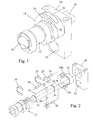
- a VET mechanism of a first embodiment of the invention comprises a drive shaft 10 that is driven in the normal manner from the engine. crankshaft.
- the illustrated mechanism serves to vary event duration and phase in a fixed relationship to one another (as shown in the valve lift diagram of Figure 4) but should it additionally be required to vary the phase of the valve events independently of any change in event duration, then it is possible to incorporate a known phase change mechanism in the pulley driving the drive shaft 10.
- the VET mechanism comprises a cam sleeve 12 that is fitted over the drive shaft 10 and can rotate freely relative to it.
- Drive is transmitted from the drive shaft 10 to the cam sleeve 12 by a crescent shaped drive member 14.
- the drive member 14 is formed integrally with a ring 16 that is journalled in a block 18.
- the ring 16 surrounds the drive shaft 10 with clearance and can be moved by sliding the block 18 up and down from a position where it is concentric with the drive shaft 10 to eccentric positions.
- Each end of the crescent of the drive member 14 is bifurcated and receives a pivot pin between its jaws.
- One of the ends 14a is pivotably connected by a pin 28 to a lollipop-shaped element 20 having a stem which is slidably received in a radial bore 22 in the drive shaft 10.
- the opposite end 14b of the drive member 14 is connected by way of a link 23 to the cam sleeve 12.
- the link 23 is doubly articulated, being pivotable about a first pin 24 relative to the drive member 14 and about a second pin 26 relative to the cam sleeve 12.
- Circlips 30 and 32 received in grooves 34 and 36 on the drive shaft 10 serve to retain the cam sleeve 12 and its drive member 14 axially on the drive shaft 10.
- the ring 16 By moving the block 18 either up or down from this position, the ring 16 will be forced to rotate about an axis that is vertically offset from the axis of the drive shaft 10. As a result, as the drive member 14 rotates, the distance of the driven end 14a from the centre of the drive shaft centre will vary cyclically during each revolution. Hence the lollipop-shaped element 20 will move in and out of the bore 22 in synchronism with the rotation of the drive shaft 10 causing a rotational oscillation of the drive member 14 around the drive shaft.
- the opposite end 14b of the drive member 14 connects to the cam sleeve 12 via the doubly articulated link 23 which moves during each revolution to compensate for the drive member 14 and cam sleeve 12 having different centres of rotation.
- This motion causes a further rotational oscillation of the cam sleeve 12 relative to the drive member 14 which superimposes upon the oscillation of the drive member 14 around the drive shaft 10 such that the phase of the cam sleeve is varied cyclically as the drive shaft rotates.
- This will result in the curves 100 and 114 at the extreme of adjustment of the block 18 in one direction and in the curves 104 and 110 at the extreme of adjustment in the opposite direction.
- the various blocks 18 for the different valves must all be movable in synchronism with one another and this can be achieved by mounting each block 18 on pins 40 that extend vertically from the cylinder head, i.e. from the face of the cylinder head on which the pillow blocks supporting the drive shaft bearings are mounted. Eccentrics 50 received in the bores 42 in the blocks 18 can be rotated in unison to raise and lower all the blocks 18 simultaneously by the same amount.
- one of the guide pins 40 may be formed with a bore 42 that communicates with an oil gallery 44 in the cylinder head. Further bores 46 in the block 18 connected to the bore 42 serve to guide the oil to the bearing surface of the ring 16, to the eccentric 50 and to the outer surfaces of the guide pins 40.
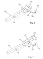
- the drive shaft 10 and the cam sleeve 12 are always concentric and they are coupled to one another by an intermediate drive member 14 that can be moved to an eccentric position.
- the intermediate drive member is omitted and instead the drive shaft 110 can be moved to an eccentric position relative to the cam sleeve 112.
- all the embodiments operate in any analogous manner to one another.
- inventions of Figures 5 to 7 also have in common with the embodiment of Figures 1 to 3, the fact that the coupling between the drive shaft 110 and the cam sleeve includes a pin slidably received in a radial bore in the drive shaft 110 and the fact that all the coupling forces acts in the same plane normal to the axis of rotation of the mechanism.
- the bearing blocks that support the drive shaft may furthermore be constructed in a similar manner to the blocks 18.
- a pin 220 is slidably received in a radial bore 122 in the drive shaft 110 the pin 220 having a tangentially extending arm 223.
- a single pivot pin 224 connects the arm 223 to the cam sleeve 112. The slidable pin 220 reciprocates radially within the bore 122 as the mechanism rotates.
- the slidable pin 320 has a cylindrical head 324 of which the axis lies parallel to the axis of rotation of the mechanism.
- the head 324 is received in a block 326 that is a force fit in a bore 328 in the cam sleeve 112.
- the pin 320 needs to move in the bore 122 to take up the eccentricity.
- the pin 420 again has a part cylindrical head 424 but this is received in a cap 426 that is retained in a cut-out 432 in the cam sleeve 112 by a clamping band 430.
- the head 424 of the pin 420 cannot move radially in relation to the cam sleeve 112 and the pin 420 must once again reciprocate within the bore 122 in the drive shaft 110.
Landscapes
- Engineering & Computer Science (AREA)
- Mechanical Engineering (AREA)
- General Engineering & Computer Science (AREA)
- Valve Device For Special Equipments (AREA)
Applications Claiming Priority (2)
| Application Number | Priority Date | Filing Date | Title |
|---|---|---|---|
| GB0019325 | 2000-08-08 | ||
| GB0019325A GB2365508A (en) | 2000-08-08 | 2000-08-08 | Variable valve timing mechanism |
Publications (2)
| Publication Number | Publication Date |
|---|---|
| EP1179657A1 true EP1179657A1 (fr) | 2002-02-13 |
| EP1179657B1 EP1179657B1 (fr) | 2006-06-21 |
Family
ID=9897107
Family Applications (2)
| Application Number | Title | Priority Date | Filing Date |
|---|---|---|---|
| EP20010000338 Expired - Lifetime EP1179657B1 (fr) | 2000-08-08 | 2001-08-02 | Distribution variable |
| EP01000345A Expired - Lifetime EP1234955B1 (fr) | 2000-08-08 | 2001-08-02 | Dispositif de distribution variable |
Family Applications After (1)
| Application Number | Title | Priority Date | Filing Date |
|---|---|---|---|
| EP01000345A Expired - Lifetime EP1234955B1 (fr) | 2000-08-08 | 2001-08-02 | Dispositif de distribution variable |
Country Status (3)
| Country | Link |
|---|---|
| EP (2) | EP1179657B1 (fr) |
| DE (2) | DE60125321T2 (fr) |
| GB (1) | GB2365508A (fr) |
Cited By (2)
| Publication number | Priority date | Publication date | Assignee | Title |
|---|---|---|---|---|
| WO2006097767A1 (fr) * | 2005-03-18 | 2006-09-21 | Mechadyne Plc | Ensemble d'arbre a cames |
| DE102013215560A1 (de) * | 2013-08-07 | 2015-02-12 | Mahle International Gmbh | Variable Nockenwelle |
Families Citing this family (4)
| Publication number | Priority date | Publication date | Assignee | Title |
|---|---|---|---|---|
| DE102012008219B4 (de) * | 2012-04-25 | 2019-05-16 | Audi Ag | Ventiltrieb einer Brennkraftmaschine |
| DE102016201264A1 (de) * | 2016-01-28 | 2017-08-03 | Mahle International Gmbh | Betriebsverfahren |
| JP2021071049A (ja) * | 2018-02-28 | 2021-05-06 | 日立Astemo株式会社 | 内燃機関のバルブタイミング制御装置 |
| GB202005068D0 (en) * | 2020-04-06 | 2020-05-20 | Pattakos Manousos | Continous variable valve duration apparatus |
Citations (3)
| Publication number | Priority date | Publication date | Assignee | Title |
|---|---|---|---|---|
| EP0801213A1 (fr) * | 1996-04-10 | 1997-10-15 | Mitsubishi Jidosha Kogyo Kabushiki Kaisha | Actionneur hydraulique et son application à un mécanisme de commande variable des soupapes |
| US5787849A (en) * | 1995-11-21 | 1998-08-04 | Mitchell; Stephen W. | Valve timing phase changer |
| US5979381A (en) * | 1995-12-12 | 1999-11-09 | Korostenski; Erwin | Valve gear mechanism for an internal combustion engine |
Family Cites Families (13)
| Publication number | Priority date | Publication date | Assignee | Title |
|---|---|---|---|---|
| GB2066361B (en) * | 1980-01-02 | 1984-07-11 | Nat Res Dev | Valve timing mechanisms of internal combustion engines |
| GB2165885B (en) * | 1984-10-20 | 1987-12-23 | Austin Rover Group | I c engine variable valve timing mechanism |
| GB2252130B (en) * | 1989-10-13 | 1994-03-30 | Rover Group | An internal combustion engine camshaft drive mechanism |
| GB9021270D0 (en) * | 1990-10-01 | 1990-11-14 | Mitchell Stephen W | Improvements in or relating to driving connections between two rotatable bodies |
| JP3177532B2 (ja) * | 1992-01-27 | 2001-06-18 | 株式会社ユニシアジェックス | 内燃機関の吸排気弁駆動制御装置 |
| DE4220668C1 (de) * | 1992-06-24 | 1993-12-09 | Daimler Benz Ag | Betätigungsvorrichtung für eine Stellklappe in Kraftfahrzeugen |
| DE4413406C2 (de) * | 1994-04-18 | 1999-05-06 | Korostenski Erwin | Brennkraftmaschine mit variabler Ventilsteuerung |
| DE4419557C1 (de) * | 1994-06-03 | 1995-10-19 | Korostenski Erwin | Brennkraftmaschine mit variabler Ventilsteuerung |
| DE59502370D1 (de) * | 1994-12-13 | 1998-07-02 | Erwin Korostenski | Ventiltrieb einer brennkraftmaschine |
| JPH08240109A (ja) * | 1995-03-03 | 1996-09-17 | Unisia Jecs Corp | 内燃機関の吸排気弁駆動制御装置 |
| AU7617696A (en) * | 1995-08-19 | 1997-03-12 | Erwin Korostenski | Internal combustion engine and process for operating the valve gear mechanism of an internal combustion engine |
| DE19643160A1 (de) * | 1995-10-18 | 1997-04-24 | Unisia Jecs Corp | Phasenverstellmechanismus für die Nockenwelle eines Verbrennungsmotors |
| JP3899576B2 (ja) * | 1997-02-07 | 2007-03-28 | 三菱自動車工業株式会社 | 可変動弁機構及び可変動弁機構付き内燃機関 |
-
2000
- 2000-08-08 GB GB0019325A patent/GB2365508A/en not_active Withdrawn
-
2001
- 2001-08-02 DE DE2001625321 patent/DE60125321T2/de not_active Expired - Fee Related
- 2001-08-02 EP EP20010000338 patent/EP1179657B1/fr not_active Expired - Lifetime
- 2001-08-02 DE DE2001620852 patent/DE60120852T2/de not_active Expired - Fee Related
- 2001-08-02 EP EP01000345A patent/EP1234955B1/fr not_active Expired - Lifetime
Patent Citations (3)
| Publication number | Priority date | Publication date | Assignee | Title |
|---|---|---|---|---|
| US5787849A (en) * | 1995-11-21 | 1998-08-04 | Mitchell; Stephen W. | Valve timing phase changer |
| US5979381A (en) * | 1995-12-12 | 1999-11-09 | Korostenski; Erwin | Valve gear mechanism for an internal combustion engine |
| EP0801213A1 (fr) * | 1996-04-10 | 1997-10-15 | Mitsubishi Jidosha Kogyo Kabushiki Kaisha | Actionneur hydraulique et son application à un mécanisme de commande variable des soupapes |
Cited By (3)
| Publication number | Priority date | Publication date | Assignee | Title |
|---|---|---|---|---|
| WO2006097767A1 (fr) * | 2005-03-18 | 2006-09-21 | Mechadyne Plc | Ensemble d'arbre a cames |
| US7958859B2 (en) | 2005-03-18 | 2011-06-14 | Mechadyne Plc | Camshaft assembly |
| DE102013215560A1 (de) * | 2013-08-07 | 2015-02-12 | Mahle International Gmbh | Variable Nockenwelle |
Also Published As
| Publication number | Publication date |
|---|---|
| EP1234955B1 (fr) | 2006-12-20 |
| GB0019325D0 (en) | 2000-09-27 |
| DE60125321T2 (de) | 2007-07-05 |
| GB2365508A (en) | 2002-02-20 |
| DE60120852T2 (de) | 2007-01-11 |
| DE60120852D1 (de) | 2006-08-03 |
| EP1234955A1 (fr) | 2002-08-28 |
| EP1179657B1 (fr) | 2006-06-21 |
| DE60125321D1 (de) | 2007-02-01 |
Similar Documents
| Publication | Publication Date | Title |
|---|---|---|
| EP1172528B1 (fr) | Commande de soupape pour moteur à combustion interne | |
| JP3606237B2 (ja) | 内燃機関 | |
| US6041746A (en) | Variable valve actuation apparatus | |
| US6382151B2 (en) | Ring gear variable valve train device | |
| JP2002523677A (ja) | カム動作システム | |
| US5732669A (en) | Valve control for an internal combustion engine | |
| EP1030035A2 (fr) | Déphaseur | |
| JP2002517669A (ja) | 内燃機関用バルブタイミング機構 | |
| JPH0941924A (ja) | 動力伝達機構及び動力伝達機構付き可変動弁機構 | |
| EP0686230B1 (fr) | Bossage de came a deplacement angulaire decale | |
| EP1179657B1 (fr) | Distribution variable | |
| JPH10317927A (ja) | 内燃機関のバルブ特性制御装置 | |
| KR20060107855A (ko) | 내연 기관용 밸브 트레인 | |
| EP1669559B1 (fr) | Mécanisme de commande de soupape | |
| CN101545387A (zh) | 用于内燃机的可变阀操作系统 | |
| EP1956200A2 (fr) | Dispositif de commande de soupape doté d'un calage et d'une durée de levée de soupape variable | |
| JP3344236B2 (ja) | 内燃機関用バルブ駆動装置 | |
| EP1697619B1 (fr) | Commande de soupapes variable | |
| JP2003083017A (ja) | バルブリフト調整装置 | |
| EP1318280A2 (fr) | Came avec période d'ouverture étendue pour un mécanisme de commande des soupapes | |
| CA2093117C (fr) | Liaison entre deux corps tournants, l'un entrainant l'autre | |
| JP4157395B2 (ja) | Ohv型内燃機関の可変動弁装置 | |
| WO2002081872A1 (fr) | Systeme de distribution a programme variable | |
| JP4011222B2 (ja) | 内燃機関の可変動弁装置 | |
| JP3383988B2 (ja) | 可変リフト弁 |
Legal Events
| Date | Code | Title | Description |
|---|---|---|---|
| PUAI | Public reference made under article 153(3) epc to a published international application that has entered the european phase |
Free format text: ORIGINAL CODE: 0009012 |
|
| AK | Designated contracting states |
Kind code of ref document: A1 Designated state(s): DE FR GB Kind code of ref document: A1 Designated state(s): AT BE CH CY DE DK ES FI FR GB GR IE IT LI LU MC NL PT SE TR |
|
| AX | Request for extension of the european patent |
Free format text: AL;LT;LV;MK;RO;SI |
|
| 17P | Request for examination filed |
Effective date: 20020709 |
|
| AKX | Designation fees paid |
Free format text: DE FR GB |
|
| 17Q | First examination report despatched |
Effective date: 20050429 |
|
| GRAP | Despatch of communication of intention to grant a patent |
Free format text: ORIGINAL CODE: EPIDOSNIGR1 |
|
| GRAS | Grant fee paid |
Free format text: ORIGINAL CODE: EPIDOSNIGR3 |
|
| GRAA | (expected) grant |
Free format text: ORIGINAL CODE: 0009210 |
|
| AK | Designated contracting states |
Kind code of ref document: B1 Designated state(s): DE FR GB |
|
| REG | Reference to a national code |
Ref country code: GB Ref legal event code: FG4D |
|
| REF | Corresponds to: |
Ref document number: 60120852 Country of ref document: DE Date of ref document: 20060803 Kind code of ref document: P |
|
| ET | Fr: translation filed | ||
| PLBE | No opposition filed within time limit |
Free format text: ORIGINAL CODE: 0009261 |
|
| STAA | Information on the status of an ep patent application or granted ep patent |
Free format text: STATUS: NO OPPOSITION FILED WITHIN TIME LIMIT |
|
| 26N | No opposition filed |
Effective date: 20070322 |
|
| PGFP | Annual fee paid to national office [announced via postgrant information from national office to epo] |
Ref country code: DE Payment date: 20070822 Year of fee payment: 7 |
|
| PGFP | Annual fee paid to national office [announced via postgrant information from national office to epo] |
Ref country code: GB Payment date: 20070823 Year of fee payment: 7 |
|
| PGFP | Annual fee paid to national office [announced via postgrant information from national office to epo] |
Ref country code: FR Payment date: 20070812 Year of fee payment: 7 |
|
| GBPC | Gb: european patent ceased through non-payment of renewal fee |
Effective date: 20080802 |
|
| REG | Reference to a national code |
Ref country code: FR Ref legal event code: ST Effective date: 20090430 |
|
| PG25 | Lapsed in a contracting state [announced via postgrant information from national office to epo] |
Ref country code: DE Free format text: LAPSE BECAUSE OF NON-PAYMENT OF DUE FEES Effective date: 20090303 Ref country code: FR Free format text: LAPSE BECAUSE OF NON-PAYMENT OF DUE FEES Effective date: 20080901 |
|
| PG25 | Lapsed in a contracting state [announced via postgrant information from national office to epo] |
Ref country code: GB Free format text: LAPSE BECAUSE OF NON-PAYMENT OF DUE FEES Effective date: 20080802 |