EP1180420A2 - Aufsatz für drehendes Handwerkzeug zum Schnitzen oder Hobeln - Google Patents
Aufsatz für drehendes Handwerkzeug zum Schnitzen oder Hobeln Download PDFInfo
- Publication number
- EP1180420A2 EP1180420A2 EP01118773A EP01118773A EP1180420A2 EP 1180420 A2 EP1180420 A2 EP 1180420A2 EP 01118773 A EP01118773 A EP 01118773A EP 01118773 A EP01118773 A EP 01118773A EP 1180420 A2 EP1180420 A2 EP 1180420A2
- Authority
- EP
- European Patent Office
- Prior art keywords
- attachment
- bit
- carving
- planing
- extension portion
- Prior art date
- Legal status (The legal status is an assumption and is not a legal conclusion. Google has not performed a legal analysis and makes no representation as to the accuracy of the status listed.)
- Granted
Links
- 238000005520 cutting process Methods 0.000 claims abstract description 31
- 210000003813 thumb Anatomy 0.000 claims abstract description 4
- 230000007704 transition Effects 0.000 claims description 10
- 229910052751 metal Inorganic materials 0.000 claims description 3
- 239000002184 metal Substances 0.000 claims description 3
- 239000000463 material Substances 0.000 description 4
- 238000010276 construction Methods 0.000 description 3
- 238000000227 grinding Methods 0.000 description 2
- 238000012986 modification Methods 0.000 description 2
- 230000004048 modification Effects 0.000 description 2
- 238000005498 polishing Methods 0.000 description 2
- 238000006467 substitution reaction Methods 0.000 description 2
- 229910000831 Steel Inorganic materials 0.000 description 1
- 229910052782 aluminium Inorganic materials 0.000 description 1
- XAGFODPZIPBFFR-UHFFFAOYSA-N aluminium Chemical compound [Al] XAGFODPZIPBFFR-UHFFFAOYSA-N 0.000 description 1
- 238000004140 cleaning Methods 0.000 description 1
- 230000000295 complement effect Effects 0.000 description 1
- 210000004247 hand Anatomy 0.000 description 1
- 230000001788 irregular Effects 0.000 description 1
- 230000000670 limiting effect Effects 0.000 description 1
- 230000035515 penetration Effects 0.000 description 1
- 239000010959 steel Substances 0.000 description 1
Images


Classifications
-
- B—PERFORMING OPERATIONS; TRANSPORTING
- B27—WORKING OR PRESERVING WOOD OR SIMILAR MATERIAL; NAILING OR STAPLING MACHINES IN GENERAL
- B27C—PLANING, DRILLING, MILLING, TURNING OR UNIVERSAL MACHINES FOR WOOD OR SIMILAR MATERIAL
- B27C1/00—Machines for producing flat surfaces, e.g. by rotary cutters; Equipment therefor
- B27C1/10—Hand planes equipped with power-driven cutter blocks
-
- B—PERFORMING OPERATIONS; TRANSPORTING
- B27—WORKING OR PRESERVING WOOD OR SIMILAR MATERIAL; NAILING OR STAPLING MACHINES IN GENERAL
- B27C—PLANING, DRILLING, MILLING, TURNING OR UNIVERSAL MACHINES FOR WOOD OR SIMILAR MATERIAL
- B27C5/00—Machines designed for producing special profiles or shaped work, e.g. by rotary cutters; Equipment therefor
- B27C5/10—Portable hand-operated wood-milling machines; Routers
-
- Y—GENERAL TAGGING OF NEW TECHNOLOGICAL DEVELOPMENTS; GENERAL TAGGING OF CROSS-SECTIONAL TECHNOLOGIES SPANNING OVER SEVERAL SECTIONS OF THE IPC; TECHNICAL SUBJECTS COVERED BY FORMER USPC CROSS-REFERENCE ART COLLECTIONS [XRACs] AND DIGESTS
- Y10—TECHNICAL SUBJECTS COVERED BY FORMER USPC
- Y10T—TECHNICAL SUBJECTS COVERED BY FORMER US CLASSIFICATION
- Y10T407/00—Cutters, for shaping
- Y10T407/19—Rotary cutting tool
- Y10T407/1946—Face or end mill
- Y10T407/1948—Face or end mill with cutting edge entirely across end of tool [e.g., router bit, end mill, etc.]
-
- Y—GENERAL TAGGING OF NEW TECHNOLOGICAL DEVELOPMENTS; GENERAL TAGGING OF CROSS-SECTIONAL TECHNOLOGIES SPANNING OVER SEVERAL SECTIONS OF THE IPC; TECHNICAL SUBJECTS COVERED BY FORMER USPC CROSS-REFERENCE ART COLLECTIONS [XRACs] AND DIGESTS
- Y10—TECHNICAL SUBJECTS COVERED BY FORMER USPC
- Y10T—TECHNICAL SUBJECTS COVERED BY FORMER US CLASSIFICATION
- Y10T407/00—Cutters, for shaping
- Y10T407/19—Rotary cutting tool
- Y10T407/195—Compound tooth arrangement
-
- Y—GENERAL TAGGING OF NEW TECHNOLOGICAL DEVELOPMENTS; GENERAL TAGGING OF CROSS-SECTIONAL TECHNOLOGIES SPANNING OVER SEVERAL SECTIONS OF THE IPC; TECHNICAL SUBJECTS COVERED BY FORMER USPC CROSS-REFERENCE ART COLLECTIONS [XRACs] AND DIGESTS
- Y10—TECHNICAL SUBJECTS COVERED BY FORMER USPC
- Y10T—TECHNICAL SUBJECTS COVERED BY FORMER US CLASSIFICATION
- Y10T409/00—Gear cutting, milling, or planing
- Y10T409/30—Milling
- Y10T409/306216—Randomly manipulated, work supported, or work following device
- Y10T409/306552—Randomly manipulated
- Y10T409/306608—End mill [e.g., router, etc.]
Definitions
- the present invention relates generally to a removable attachment for use with a rotary hand tool. More specifically, the present invention relates to a removable attachment which is adapted to be used for carving and/or planing tasks.
- the attachment is used in conjunction with an elongated drywall cutting bit or similar side cutting bit that is installed in the tool.
- attachments are currently available for use with rotary hand tools (such as those marketed under the Dremel brand made by the S-B Power Tool Company of Chicago, Illinois) to aid the user in performing specialized tasks more accurately or more efficiently.
- Such attachments include various guide attachments for controlling the depth of cut and angle of penetration while performing various tasks that relate to making, maintaining and/or repairing objects or work surfaces.
- Such rotary hand tools are often supplied with a flexible drive shaft that attaches to the nose portion of the hand tool itself and provides several feet of flexible extension with the bits being attached to the outer end of the extension. This enables the power unit to be suspended from a support and enables the user to control the bit rather than the power unit, which obviously is much lighter and enables more convenient usage in hard to access locations.
- drywall cutting bits which generally have a number of flutes in the side thereof, with the end that is inserted into the collet being smooth and the cutting bit having a smooth outer end.
- the bits are approximately 1/8 inch in diameter and may be up to 2 inches in length.
- the elongated drywall cutting bit as well as other side cutting bits may conveniently be used to perform carving or planing tasks with the advantage that a relatively wide swath can be made because of the length of the cutting surface of the bit.
- control of such cutting action is in large part a function of the skill of the user in that the amount of downward force applied to the bit during operation can vary the depth of cut.
- the cutting action can be quite irregular due to the variation in the softness of the material that is being worked on and the dexterity of the user.
- Another object of the present invention is to provide such an attachment which enables the user to apply varying degrees of force to the bit without gouging the work piece to any significant degree regardless of the amount of force that is applied.
- Still another object of the present invention is to provide such an attachment that is simple in its design and construction, comprises a unitary piece that is easily attached and is easy to use.
- Yet another object of the present invention is to provide such an attachment that is adapted to be applied to the hand tool drive unit itself, or alternatively be attached to a flexible drive shaft extension or other attachment such as a right angle attachment.
- Still another object of the present invention lies in the provision for applying substantial force to the drill bit without gouging in that the attachment prevents the bit from cutting more than a known predetermined amount during any one pass across the volume of the work piece.
- the present invention is directed to an attachment for a rotary hand tool of the type which has an electric motor that is relatively small in size and which has an output shaft or spindle to which a collet may be screwed on, with the collet being adapted to hold bits of various kinds for performing various tasks such as woodworking or other tasks such as polishing, grinding, sanding, cutting, and the like.
- the present invention is directed to an attachment for use in connection with a drywall cutting bit or other side cutting elongated bit which is used to carve or plane a work piece.
- the carving and/or planing attachment is adapted to be mounted to the nose piece of the rotary tool or to the outer end of a flexible drive extension or any other suitable attachment such as a right angle attachment and encircles the collet and bit at the base end portion of the attachment.
- the carving and/or planing attachment embodying the present invention has an extension portion that extends along the length of the bit and partially encircles it, providing a planar surface that limits the depth of engagement by the bit during operation.
- the extension has a semi-cylindrical surface portion that contacts a smooth outer end portion of the cutting bit and provides support to the bit so that it cannot be deflected and cut into the extension portion of the attachment.
- a recess in the back of the attachment is adapted to provide a nonslip surface into which the end of a user's thumb may rest for the purpose of applying downward force to the attachment during operation.
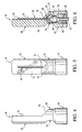
- FIGS. 1-6 the carving and/or planing attachment indicated generally at 10 is shown in FIGS. 1-6 and is adapted to be attached to a rotary hand tool indicated generally at 12 in FIG. 7 or to a flexible extension that may be attached to the threaded nose 19.
- the hand tool 12 has a motor 14, a housing 16, with a threaded nose 18 and an output spindle 20 that has a threaded portion onto which a collet 22 (FIG. 6) can be screwed on.
- the collet is of conventional design, having an outer nut 24 that is rotatably coupled to a stationary portion that is threaded onto the spindle 26 and contains a split ring collet which is sized to accept a predetermined sized bit, such as the bit indicated generally at 28 shown in FIG. 6.
- the bit 28 has a smooth outer end portion 30, a smooth shank 32 that fits within the collet 22, and a fluted side portion 34 located therebetween with the portion 34 being adapted to perform a cutting or planing action during operation.
- Such bits 28 are commercially available as drywall cutting bits, but other side cutting bits are also available.
- a drive means such as a flexible shaft attachment as shown in FIG. 7 is available for connection to the hand tool 12, with. the attachment generally indicated at 36 having a connector portion 38.
- the extension has a connector portion 38 which has internal threads that engage the threaded nosepiece 19 when installed and the connector portion is connected to an outer sheath 40 that terminates in a threaded attachment nose portion 42 that is similar in construction to the threaded nose portion 18.
- the attachment 36 has an internal flexible shaft 44 that is connected to the spindle via a keyed connector 46 with the connector being attached to the spindle 20 said having a keyed inner configuration that is complementary to the shape of the end of the shaft 44.
- the shaft 44 terminates in a spindle structure 50 which is threaded and of the same size as the spindle 20.
- a collet such as collet 22 can be attached to the spindle portion 50 and be adapted to retain a bit such as the bit 29 shown in FIG. 6.
- Other drive means such as a right angle attachment, is available and similarly attaches to the nosepiece 19 and has an internal flexible shaft that is connected to the spindle and has an output spindle structure similar to structure 50 and has a housing to which the carving and/or planing attachment of the present invention can be attached.
- the attachment is preferably of unitary construction and may be made of metal, such as aluminum, steel or other metal, or it may be tirade of a plastic or plastic-like material.
- the attachment 10 has an overall cylindrical shape with a base portion indicated generally at 54, a transition portion indicated generally at 56 and an extension portion indicated generally at 58.
- the attachment may be made in two pieces with the transition and/or extension portion being rotatable relative to the base portion to vary the circumferential position of the cutting bit relative to the hand tool itself.
- the base portion 54 is in the form of a hollow cylinder, with the inside of the cylinder being identified at 60 and having interior threads 62 which are adapted to engage the threaded nose portion 18 or the threaded nose portion 42 when installed on the rotary hand tool or an extension thereof.
- the interior 60 transitions to a chamber 64 that is cylindrical in shape and of a diameter sufficient to enable the collet 22 to be located therein, with the top of the chamber 64 having a conical shape 66 which transitions to an aperture 68 through which the bit 28 can pass. While the chamber of the preferred embodiment is shown to be closed, it should be understood that it need not be, i.e., there may be one or more openings in the side wall of the attachment adjacent the chamber.
- the aperture 68 continues to the extension portion 58 but becomes a semi-cylindrical aperture such as shown in FIG. 5 and in the cross section of FIG. 6.
- the bit 28 is adapted to fit within the aperture 68 and its semi-cylindrical recess portion, with the extension portion providing support for the bit 28 during operation. This is achieved by the smooth non-cutting end portion 30 of the bit engaging the depth of the recess 68, with the material of the extension portion providing support for the bit during operation.
- the transition portion 56 has an inclined face 70 extending from the outer diameter of the front inwardly toward the aperture 68 and terminating in a planar surface 72 at line 74 that approximately intercepts the center of the aperture 68 which necessarily corresponds to the center of the bit 29 as well.
- the attachment may be constructed so that the location of the planar surface 72 relative to the aperture may be different from that shown to expose more or less of the bit to a work piece.
- the plane or surface 72 were more rightward relative to the bit as shown in FIG. 6. there would be less of the bit protruding from the plane or surface 72 which would reduce the possible depth of cut during use.
- the position of the plane or surface 72 were moved to the left relative to the bit so as to expose more of the bit, then the bit would be available to provide a deeper cut during a pass through the work piece.
- the inclined portion 70 is shown to be approximately 45° and intercepts the plane of the area 72 at fine 74, which provides a guide for the user during operation. If a work piece is engaged by the surface 70 and the user applies force intending to bring the bit into engagement with the work piece, the inclined portion 70 will tend to position the attachment and tool relative to the workplace so that the cutting surface of the bit will engage the workplace approximately at the location of the line 74. It should be understood that the angle of the surface 70 maybe greater or less than the approximate 45 degree angle shown and may in fact be curved if desired.
- a recess 76 may be provided in the back of the attachment in the transition portion. It should be understood that the shape of the recess 56, while circular in shape from the side as shown in FIG. 4, may be some other curved shape and may in fact be planar if desired. The purpose of the recess is to provide a convenient surface where the user can apply force with his thumb or other portion of his hands to increase the speed of cut or otherwise more conveniently control the attachment.
- an improved attachment for use with rotary hand tools has been shown and described which has significant attributes and advantages in carrying out carving and/or planing operations on a work piece in a manner whereby the potential of gouging the work piece is significantly minimized because of the presence of the extension portion of the attachment surrounding the cutting bit.
- the extension portion is adapted to contact the work piece and prevent the cutting bit from cutting deeper than a known amount.
- the size and shape of the attachment is conducive to highly efficient rapid and easy operation.
Landscapes
- Life Sciences & Earth Sciences (AREA)
- Engineering & Computer Science (AREA)
- Mechanical Engineering (AREA)
- Wood Science & Technology (AREA)
- Forests & Forestry (AREA)
- Milling, Drilling, And Turning Of Wood (AREA)
- Gripping On Spindles (AREA)
- Processing Of Stones Or Stones Resemblance Materials (AREA)
- Drilling Tools (AREA)
Applications Claiming Priority (2)
| Application Number | Priority Date | Filing Date | Title |
|---|---|---|---|
| US09/642,295 US6491483B1 (en) | 2000-08-18 | 2000-08-18 | Carving/planing attachment for a rotary hand tool |
| US642295 | 2000-08-18 |
Publications (3)
| Publication Number | Publication Date |
|---|---|
| EP1180420A2 true EP1180420A2 (de) | 2002-02-20 |
| EP1180420A3 EP1180420A3 (de) | 2002-02-27 |
| EP1180420B1 EP1180420B1 (de) | 2004-10-20 |
Family
ID=24576018
Family Applications (1)
| Application Number | Title | Priority Date | Filing Date |
|---|---|---|---|
| EP01118773A Expired - Lifetime EP1180420B1 (de) | 2000-08-18 | 2001-08-08 | Aufsatz für drehendes Handwerkzeug zum Schnitzen oder Hobeln |
Country Status (3)
| Country | Link |
|---|---|
| US (1) | US6491483B1 (de) |
| EP (1) | EP1180420B1 (de) |
| DE (1) | DE60106539T2 (de) |
Cited By (1)
| Publication number | Priority date | Publication date | Assignee | Title |
|---|---|---|---|---|
| WO2005110689A3 (en) * | 2004-04-06 | 2006-02-16 | Bosch Gmbh Robert | Planing/chamfering attachment for a rotary hand tool |
Families Citing this family (6)
| Publication number | Priority date | Publication date | Assignee | Title |
|---|---|---|---|---|
| JP4087608B2 (ja) * | 2002-01-25 | 2008-05-21 | オークマ株式会社 | 切削工具、および該切削工具を用いた切削加工方法 |
| US6796755B2 (en) * | 2002-09-03 | 2004-09-28 | Joseph J. Angeloni | Guide for rotary cutter |
| DE10393255T5 (de) | 2002-09-03 | 2005-08-18 | Kennametal Inc. | Werkzeughalter |
| US20090183887A1 (en) * | 2008-01-18 | 2009-07-23 | Credo Technology Corporation | Power hand tool system with universal flexible shaft and method of operating |
| JP5963292B2 (ja) * | 2013-07-01 | 2016-08-03 | 国立大学法人名古屋大学 | エンドミル加工装置およびcam装置およびncプログラム |
| USD1050857S1 (en) | 2020-05-19 | 2024-11-12 | Techtronic Cordless Gp | Accessory for planer attachment |
Family Cites Families (8)
| Publication number | Priority date | Publication date | Assignee | Title |
|---|---|---|---|---|
| DE954737C (de) | 1954-08-17 | 1956-12-20 | Albert Fezer | Motorhandfraesgeraet, insbesondere zur Furnierbearbeitung |
| FR2439651A1 (fr) | 1978-10-27 | 1980-05-23 | Orblin Charles | Machine a lame rotative notamment utilisable comme tronconneuse |
| AT371745B (de) * | 1979-06-26 | 1983-07-25 | Linsinger Ernst Dipl Ing Dr | Verfahren und werkzeug zum beseitigen des brenngrates an den kanten brenngeschnittener blechteile |
| US4359302A (en) | 1979-11-28 | 1982-11-16 | Bryan Payne | Method for cutting wallboards |
| US4674548A (en) | 1985-12-26 | 1987-06-23 | The Boeing Company | Adjustable router |
| US5224803A (en) * | 1991-10-28 | 1993-07-06 | Guy Lallier | Router device |
| US5224230A (en) * | 1992-02-03 | 1993-07-06 | Vanicsek Paul K | Router-bit drywall cutter |
| WO1997029880A1 (en) * | 1996-02-13 | 1997-08-21 | Robert Maurice Renn | Miniature all-purpose tool |
-
2000
- 2000-08-18 US US09/642,295 patent/US6491483B1/en not_active Expired - Lifetime
-
2001
- 2001-08-08 EP EP01118773A patent/EP1180420B1/de not_active Expired - Lifetime
- 2001-08-08 DE DE60106539T patent/DE60106539T2/de not_active Expired - Lifetime
Cited By (2)
| Publication number | Priority date | Publication date | Assignee | Title |
|---|---|---|---|---|
| WO2005110689A3 (en) * | 2004-04-06 | 2006-02-16 | Bosch Gmbh Robert | Planing/chamfering attachment for a rotary hand tool |
| US7168897B2 (en) | 2004-04-06 | 2007-01-30 | Robert Bosch Gmbh | Planing/chamfering attachment for a rotary hand tool |
Also Published As
| Publication number | Publication date |
|---|---|
| DE60106539T2 (de) | 2006-03-09 |
| EP1180420A3 (de) | 2002-02-27 |
| US6491483B1 (en) | 2002-12-10 |
| DE60106539D1 (de) | 2004-11-25 |
| EP1180420B1 (de) | 2004-10-20 |
Similar Documents
| Publication | Publication Date | Title |
|---|---|---|
| US6814157B2 (en) | Rotary tool flex shaft with lock pin and end cap | |
| CN101426620B (zh) | 电动工具保护装置 | |
| US5639273A (en) | Grinding cup and holder device | |
| US9302329B2 (en) | Bi-directional quick change tool-less lever and wedge actuated collet chuck, system and/or method for using the same | |
| US7677281B2 (en) | Power router tool | |
| US6106372A (en) | Tungsten electrode sharpener | |
| US4319503A (en) | Tube facing machine | |
| CA2562302C (en) | Planing/chamfering attachment for a rotary hand tool | |
| US20020148333A1 (en) | Automated pipe cutter tool box | |
| US6491483B1 (en) | Carving/planing attachment for a rotary hand tool | |
| US6044559A (en) | Cutting blade and stabilizing handle attachments for a power drill | |
| US7048617B1 (en) | Method and apparatus for smoothing unfinished surfaces | |
| US7530884B2 (en) | System and method for duplicating keys | |
| KR102025515B1 (ko) | 조각도 연마 장치 | |
| JPH081491A (ja) | 面取り装置 | |
| US20210101248A1 (en) | Method and apparatus for forming holes | |
| JP2552389Y2 (ja) | 円錐形切削工具の研磨装置 | |
| KR20040077237A (ko) | 연마 가공물 고정용 지그 | |
| CA2310118A1 (en) | An edge trimming tool | |
| JP2002137106A (ja) | マシニングセンタ等の工作機用研削及び研磨工具の保持具 | |
| JPH05154710A (ja) | 穿孔装置 | |
| JPH11320252A (ja) | ハンド型面取り加工機 | |
| JP2564987Y2 (ja) | くり抜き作業用アタッチメント | |
| KR200226443Y1 (ko) | 중심고정날이 구비된 코어드릴 | |
| JPH09136301A (ja) | 座掘りカッター |
Legal Events
| Date | Code | Title | Description |
|---|---|---|---|
| PUAI | Public reference made under article 153(3) epc to a published international application that has entered the european phase |
Free format text: ORIGINAL CODE: 0009012 |
|
| PUAL | Search report despatched |
Free format text: ORIGINAL CODE: 0009013 |
|
| AK | Designated contracting states |
Kind code of ref document: A2 Designated state(s): AT BE CH CY DE DK ES FI FR GB GR IE IT LI LU MC NL PT SE TR Kind code of ref document: A2 Designated state(s): DE FR GB |
|
| AX | Request for extension of the european patent |
Free format text: AL;LT;LV;MK;RO;SI |
|
| AK | Designated contracting states |
Kind code of ref document: A3 Designated state(s): AT BE CH CY DE DK ES FI FR GB GR IE IT LI LU MC NL PT SE TR |
|
| AX | Request for extension of the european patent |
Free format text: AL;LT;LV;MK;RO;SI |
|
| 17P | Request for examination filed |
Effective date: 20020822 |
|
| AKX | Designation fees paid |
Free format text: DE FR GB |
|
| GRAP | Despatch of communication of intention to grant a patent |
Free format text: ORIGINAL CODE: EPIDOSNIGR1 |
|
| GRAS | Grant fee paid |
Free format text: ORIGINAL CODE: EPIDOSNIGR3 |
|
| GRAA | (expected) grant |
Free format text: ORIGINAL CODE: 0009210 |
|
| RAP1 | Party data changed (applicant data changed or rights of an application transferred) |
Owner name: CREDO TECHNOLOGY CORPORATION |
|
| AK | Designated contracting states |
Kind code of ref document: B1 Designated state(s): DE FR GB |
|
| REG | Reference to a national code |
Ref country code: GB Ref legal event code: FG4D |
|
| REG | Reference to a national code |
Ref country code: IE Ref legal event code: FG4D |
|
| REF | Corresponds to: |
Ref document number: 60106539 Country of ref document: DE Date of ref document: 20041125 Kind code of ref document: P |
|
| ET | Fr: translation filed | ||
| PLBE | No opposition filed within time limit |
Free format text: ORIGINAL CODE: 0009261 |
|
| STAA | Information on the status of an ep patent application or granted ep patent |
Free format text: STATUS: NO OPPOSITION FILED WITHIN TIME LIMIT |
|
| 26N | No opposition filed |
Effective date: 20050721 |
|
| PGFP | Annual fee paid to national office [announced via postgrant information from national office to epo] |
Ref country code: FR Payment date: 20090819 Year of fee payment: 9 |
|
| REG | Reference to a national code |
Ref country code: FR Ref legal event code: ST Effective date: 20110502 |
|
| PG25 | Lapsed in a contracting state [announced via postgrant information from national office to epo] |
Ref country code: FR Free format text: LAPSE BECAUSE OF NON-PAYMENT OF DUE FEES Effective date: 20100831 |
|
| PGFP | Annual fee paid to national office [announced via postgrant information from national office to epo] |
Ref country code: GB Payment date: 20180828 Year of fee payment: 18 |
|
| PGFP | Annual fee paid to national office [announced via postgrant information from national office to epo] |
Ref country code: DE Payment date: 20181024 Year of fee payment: 18 |
|
| REG | Reference to a national code |
Ref country code: DE Ref legal event code: R119 Ref document number: 60106539 Country of ref document: DE |
|
| GBPC | Gb: european patent ceased through non-payment of renewal fee |
Effective date: 20190808 |
|
| PG25 | Lapsed in a contracting state [announced via postgrant information from national office to epo] |
Ref country code: DE Free format text: LAPSE BECAUSE OF NON-PAYMENT OF DUE FEES Effective date: 20200303 |
|
| PG25 | Lapsed in a contracting state [announced via postgrant information from national office to epo] |
Ref country code: GB Free format text: LAPSE BECAUSE OF NON-PAYMENT OF DUE FEES Effective date: 20190808 |