EP1180701A1 - Ensemble d'un connecteur optique et d'un circuit imprimé avec connexion mobile - Google Patents
Ensemble d'un connecteur optique et d'un circuit imprimé avec connexion mobile Download PDFInfo
- Publication number
- EP1180701A1 EP1180701A1 EP01117686A EP01117686A EP1180701A1 EP 1180701 A1 EP1180701 A1 EP 1180701A1 EP 01117686 A EP01117686 A EP 01117686A EP 01117686 A EP01117686 A EP 01117686A EP 1180701 A1 EP1180701 A1 EP 1180701A1
- Authority
- EP
- European Patent Office
- Prior art keywords
- base
- outer housing
- optical connector
- spring
- optical fiber
- Prior art date
- Legal status (The legal status is an assumption and is not a legal conclusion. Google has not performed a legal analysis and makes no representation as to the accuracy of the status listed.)
- Withdrawn
Links
- 230000003287 optical effect Effects 0.000 title claims abstract description 74
- 239000013307 optical fiber Substances 0.000 claims abstract description 54
- 230000013011 mating Effects 0.000 claims description 14
- 238000000034 method Methods 0.000 claims description 3
- 238000006073 displacement reaction Methods 0.000 claims 4
- 230000000712 assembly Effects 0.000 description 3
- 238000000429 assembly Methods 0.000 description 3
- 239000000835 fiber Substances 0.000 description 3
- 239000002991 molded plastic Substances 0.000 description 3
- 230000006835 compression Effects 0.000 description 2
- 238000007906 compression Methods 0.000 description 2
- 230000009977 dual effect Effects 0.000 description 2
- 238000000605 extraction Methods 0.000 description 2
- 238000003780 insertion Methods 0.000 description 2
- 230000037431 insertion Effects 0.000 description 2
- 239000000463 material Substances 0.000 description 2
- 238000012986 modification Methods 0.000 description 2
- 230000004048 modification Effects 0.000 description 2
- 239000002861 polymer material Substances 0.000 description 2
- 230000003993 interaction Effects 0.000 description 1
- 238000004519 manufacturing process Methods 0.000 description 1
Images

Classifications
-
- G—PHYSICS
- G02—OPTICS
- G02B—OPTICAL ELEMENTS, SYSTEMS OR APPARATUS
- G02B6/00—Light guides; Structural details of arrangements comprising light guides and other optical elements, e.g. couplings
- G02B6/24—Coupling light guides
- G02B6/36—Mechanical coupling means
- G02B6/38—Mechanical coupling means having fibre to fibre mating means
- G02B6/3807—Dismountable connectors, i.e. comprising plugs
- G02B6/381—Dismountable connectors, i.e. comprising plugs of the ferrule type, e.g. fibre ends embedded in ferrules, connecting a pair of fibres
- G02B6/3818—Dismountable connectors, i.e. comprising plugs of the ferrule type, e.g. fibre ends embedded in ferrules, connecting a pair of fibres of a low-reflection-loss type
- G02B6/3821—Dismountable connectors, i.e. comprising plugs of the ferrule type, e.g. fibre ends embedded in ferrules, connecting a pair of fibres of a low-reflection-loss type with axial spring biasing or loading means
-
- G—PHYSICS
- G02—OPTICS
- G02B—OPTICAL ELEMENTS, SYSTEMS OR APPARATUS
- G02B6/00—Light guides; Structural details of arrangements comprising light guides and other optical elements, e.g. couplings
- G02B6/24—Coupling light guides
- G02B6/36—Mechanical coupling means
- G02B6/38—Mechanical coupling means having fibre to fibre mating means
- G02B6/3807—Dismountable connectors, i.e. comprising plugs
- G02B6/3897—Connectors fixed to housings, casing, frames or circuit boards
-
- G—PHYSICS
- G02—OPTICS
- G02B—OPTICAL ELEMENTS, SYSTEMS OR APPARATUS
- G02B6/00—Light guides; Structural details of arrangements comprising light guides and other optical elements, e.g. couplings
- G02B6/24—Coupling light guides
- G02B6/36—Mechanical coupling means
- G02B6/38—Mechanical coupling means having fibre to fibre mating means
- G02B6/3807—Dismountable connectors, i.e. comprising plugs
- G02B6/389—Dismountable connectors, i.e. comprising plugs characterised by the method of fastening connecting plugs and sockets, e.g. screw- or nut-lock, snap-in, bayonet type
- G02B6/3893—Push-pull type, e.g. snap-in, push-on
Definitions
- the present invention relates to optical connectors and, more particularly, to a movable connection of an optical connector to a printed circuit board.
- U.S. Patent 4,432,604 discloses a self-adjusting fiberoptic connector assembly having optical fiber plugs connected to a backplane by movable brackets.
- U.S. Patent 5,828,805 discloses a multifiber optical connector plug.
- U.S. Patent 4,361,372 discloses a connector panel for an electronic cabinet having spring-loaded cells for a floating plate on a connector panel.
- an optical connector assembly comprising a base, an optical fiber connector, and a spring.
- the base is adapted to be fixedly attached to a printed circuit board.
- the optical fiber connector has an outer housing movably mounted to the base. The spring biases the optical fiber connector in a predetermined direction relative to the base.
- an electronic and optical assembly comprising a printed circuit board; and an optical fiber connector mounted on the printed circuit board. A portion of the optical connector extends beyond an edge of the printed circuit board.
- the optical connector is movably mounted to move inward and outward relative to the edge.
- an optical connector assembly comprising: a ferrule and optical fiber subassembly, an outer housing, a base, and a spring.
- the outer housing surrounds the subassembly.
- the subassembly is movable in a longitudinal direction in the outer housing.
- the base is connected to the outer housing.
- the outer housing is movable relative to the base.
- the base is adapted to be fixedly attached to a printed circuit board.
- the spring biases the outer housing in a predetermined direction relative to the base.
- an arrangement usable in a connector for an optical fiber having a front end allowing to make contact with another optical fiber, and the arrangement comprising at least two spring type elements, wherein each spring type element is arranged in such a manner that it is capable of providing a force to the optical fiber, the force having a component in an orientation which is orthogonal to the front end.
- connection system comprising:
- a method of assembling an optical connector assembly comprising steps of providing an optical connector comprising an outer housing and a ferrule and optical fiber assembly located inside the housing; providing a base adapted to be fixedly attached to a printed circuit board; and movably mounting the optical connector to the base and biasing the outer housing of the optical connector in a predetermined direction relative to the base.
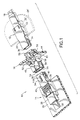
- FIG. 1 there is shown a partial exploded perspective view of a backplane connection system 10 incorporating features of the present invention.
- a backplane connection system 10 incorporating features of the present invention.
- the present invention will be described with reference to the single embodiment shown in the drawings, it should be understood that the present invention can be embodied in many alternate forms of embodiments.
- any suitable size, shape or type of elements or materials could be used.
- the backplane connection system 10 generally comprises a first optical cable assembly 12, a combined printed circuit board and optical cable assembly 14, and a backplane assembly 16.
- the first optical cable assembly 12 generally comprises an optical fiber cable 18 preferably having multiple optical fibers and an optical connector 20.
- the connector 20 could be any suitable optical connector, such as described in U.S. Patent No. 5,828,805. Ferrules of the connector 20 precisely locate ends of the optical fibers in the connector 20 at a front end of the ferrules.
- the connector 20 includes an outer housing 22.
- the outer housing 22 includes enlarged recesses 24 on its sides for connection with the backplane assembly 16.
- the connector 20 could have any suitable configuration or features.
- the combined printed circuit board and optical cable assembly 14 generally comprises a daughter printed circuit board 26, a second optical cable assembly 28 and a connecting assembly 30.
- the second optical cable assembly 28 generally comprises an optical fiber cable 32 and an optical connector 34.
- the optical fiber cable 32 preferably comprises multiple optical fibers.
- the optical connector 34 is similar to the connector described in U.S. patent No. 5,828,805. Ferrules of the connector 34 precisely locate ends of the optical fibers at front ends of the ferrules. Pins (not shown) extending out the front end of a ferrule of one of the connectors 20 or 34, are matingly received in holes of a ferrule in the mating connector when the front ends 36, 38 of the connectors 20, 34 are mated to each other.
- the connector 34 includes an outer housing 40.
- the outer housing 40 includes enlarged recesses 42 on its sides for connection with the backplane assembly 16.
- the backplane assembly 16 generally comprises a backplane member 44 and an optical connector adapter 46.
- the backplane member 44 is a mother printed circuit board or multi-layer board.
- the mother printed circuit board 44 preferably comprises at least one card edge connector (not shown) or other type of electrical connector on a front side 45 for making electrical connection with contacts (not shown) on daughter printed circuit boards; including a connector for the daughter board 26.
- the adapter 46 is fixedly connected to the mother board 44 in a hole between front and rear sides of the mother board.
- the adapter 46 generally comprises a housing 50 and a mounting clip 52.
- the adapter housing 50 preferably is a molded plastic member. Typically, the housing 50 is made from two pieces bonded together before mounting on the board 44.
- the adapter housing 50 includes an open center channel 54 and opposite open ends 56 into the channel 54.
- the adapter housing 50 also includes resilient latch arms 58 on sides of the adapter housing.
- the latch arms 58 are adapted to interact with the enlarged recesses 24, 42 in the connector outer housings 22, 40 to independently mount the connectors 20, 34 to the adapter housing 50.
- An adapter assembly similar to the adapter housing 50 is available from FCI Electronics of Etters, PA, USA as part number 86144.
- the adapter 46 generally functions as a support for connecting the two optical connectors 20, 34 to each other at a predetermined location; one of the connectors 34 being located on a daughter printed circuit board.
- the optical connectors 20, 34 can have any suitable type of configuration. In alternate embodiments, features of the present invention could be used with any suitable backplane member, or optical connector adapter, or in any suitable system for connecting two optical connectors to each other.
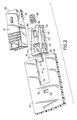
- the daughter board 26 preferrably comprises two mounting holes 60, 62 proximate an edge 64.
- the first hole 60 is open at the edge 64.
- the hole 60 need not be open at the edge, or the daughter board could have more or less than two mounting holes.
- the connecting assembly 30 generally comprises a base 66 and a spring 68.
- the base 66 is a one-piece member preferably comprised of a molded plastic or polymer material. However, the base could be comprised of multiple members and any suitable type(s) of material could be used.
- the base 66 generally comprises a latch 70, two side slots 72 and a recess 74 in a top surface 76.
- the latch 70 is a cantelevered snap-lock latch adapted to snap over the portion 78 of the daughter board 26 into the second hole 62.
- the base 66 can rest against the surface 82 in the first hole 60.
- the two side slots 72 slidingly receive portions of the daughter board 26 on sides of the first hole 60.
- the base 66 is slid into the first hole 60 as indicated by arrow A.
- the recess 74 generally comprises a spring locating area 84, a dovetail groove 86, and ramp and hole areas 88, 90 that form a stop surface 92.
- the base 66 has a spring support rod 94 extending into the spring locating area 84.
- the dovetail groove 86 extends to the spring locating area 84 from the end 96 of the base 66.
- the base 66 could have any suitable shape or configuration.
- the areas 84, 86, 88, 90 and/or stop surface 92 could also have any suitable shape or configuration.
- the spring 68 is located in the spring locating area 84.
- the spring 68 is a coil spring.
- any suitable type of spring could be used.
- the spring could also be formed integrally with the base 66 and/or outer housing 40, or could be mounted to the outer housing 40 rather than the base 66.
- One end of the spring rests against the surface 98 in the spring locating area 84 and the other end of the spring rests against a portion of the outer housing 40 of the connector 34.
- the connector 34 generally comprises the outer housing 40, a subassembly 100 and a spring 102.
- Spring 102 allows fine adjustment of the fibers with the fibers in a mating connector, for example, to absorb tolerance differences within the connectors.
- the subassembly 100 generally comprises two ferrule members 104, and inner housing 106, and ends 108 of the optical fibers from the cable 32. The ends 108 are sandwiched between the two ferrule members 104.
- the inner housing 106 retains the two ferrule members together.
- the inner housing 106 includes grooves 110. Portions 112 of the outer housing 40 extend into the grooves 110.
- the subassembly 100 can longitudinally slide in the outer housing 40.
- the interaction between the portions 112 and the grooves 110 functions as limits to forward and rearward motion of the subassembly 100 in the outer housing 40.
- the spring 102 biases the subassembly 100 in a forward direction.
- Spring 102 allows for rough or coarse adjustment of the connector in order to absorb tolerance differences in the boards 26, 26'.
- the spring 102 can be compressed as the front end 114 of the subassembly 100 is pushed into the front end of the outer housing 40 when the front end 114 makes contact with the front end of the mating connector 20.
- the spring 102 can thus allow for specific ferrule compression or mating force which is desired in a backplane fiber optic connector.
- the connector 34 allows for a ⁇ 2 mm longitudinal mismatch when the connectors 20, 34 are connected to the adapter 46.
- a boot 116 is provided as a strain relief for the cable 32.
- any suitable optical fiber and ferrule subassembly could be provided and any suitable system for movably mounting the subassembly to the outer housing could be provided.
- the subassembly could be stationarily connected to the outer housing.
- the outer housing 40 is preferably a one-piece member comprised of molded plastic or polymer material.
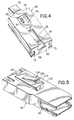
- the outer housing 40 comprises a top side with a guide stop 118 (see Figs. 1 and 3) and a bottom side 120.
- the bottom side 120 includes a guide rail section 122 and a resiliently deflectable stop latch 124.
- the guide rail section 122 has a cross-sectionally complimentary shape to the cross-sectional shape of the groove 86 in the base.
- the guide rail section 122 has a dovetail cross-sectional shape.
- any suitable, slidably interlocking shapes could be provided for the groove 86 and guide rail section 122.
- the latch 124 extends downward from the guide rail section 122.
- An end 126 (stop projection) of the latch 124 is adapted to contact the stop surface 92 of the base 66 to limit movement of the outer housing 40 on the base 66 in direction B (see Fig. 3).
- the guide rail section 122 is slid into the groove 86 from rear end 96 of the base 66.
- the latch 124 is deflected upward and then snaps back downward behind the stop surface 92.
- the rear end 128 of the guide rail section 122 forms a spring contact surface for contacting an end of the spring 68 in the base 66.
- the spring 68 biases the outer housing 40 in direction B on the base 66 with the latch 124 locating the outer housing at a predetermined position on the base.
- the outer housing 40 can be moved in direction A relative to the base 66 with the spring 68 being compressed between the surfaces 128 and 98.
- any suitable type of movable interconnection between the optical connector and the base could be provided.
- the outer housing 40 is movably mounted to the daughter board 26.
- This provides a dual type of Z axis float.
- the first type of Z axis float can compensate for the connections between the connectors 20, 34 and the adapter 46 while still providing a desired predetermined compression mating force between the front ends of the ferrules of the two connectors.
- the second type of Z axis float can compensate for Z axis differentials between the connector 34 and the adapter 46, and electrical connection(s) between the daughter board 26 and the mother board 44.
- An alternative solution would be to merely lengthen the spring 102 and keep the outer housing stationarily connected to the daughter board.
- the spring assembly can also provide float in the X- and Y-axes.
- the connector 34 When the connector 34 is inserted into the adapter 46 and is fully inserted, the outer housing 40 will stop against the adapter housing 50. However, the daughter board 26 can continue to move in the Z direction to compensate for tolerances in the backplane assembly.
- the connector 34 will be at the correct depth of insertion in the adapter 46 without exposing the ferrule subassembly 100 to any of the forces associated with daughter board/mother board connection tolerances.
- the present invention allows for daughter board card edge connections at both front and rear sides of the backplane assembly, such as shown by dotted lines in Fig. 1 with board 26' and connecting assembly 30'.
- the present invention allows use of standard conventional springs as the springs 102 in the optical connector 34 so the correct ferrule mating force will be achieved.
- the present invention allows backplane assemblies to be built with greater tolerances; thereby reducing manufacturing costs.
- the present invention can also allow easier removal of the assembly 14 from the backplane assembly 16 by allowing the card 26 to start to move away from the mother board 44 before disconnection forces are encountered between the connector outer housing 40 and the adapter housing 50. It is also relatively easy to disconnect the connector 34 from the base 66 by merely inserting a tool (not shown) in the bottom of the hole 90 to deflect the latch 124 upward past the stop surface 92 and then merely slide the connector 34 in direction B off of the base 66, such as for repair or replacement of the optical cable assembly 28.
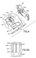
- the system generally comprises a daughter board 26", a connecting assembly 200, and a conventional optical cable assembly 202.
- the daughter board 26" has a hole 60" which receives the base 201.
- the hole 60" is spaced from the edge 64", but the card 26" could have the same holes 60, 62 as shown in Fig. 2, such as if the base 201 had attachment means 70, 72. Any suitable means could be used to attach the base 201 to the daughter board 26".
- the optical cable assembly 202 generally corresponds to a conventional optical cable assembly, such as having an adapter assembly available from FCI Electronics of Etters, PA as part number 86144.
- the outer housing 204 of the assembly 202 includes two mounting posts 206.
- the mounting posts 206 were originally designed for through-hole mounting of the posts in holes of a daughter board.
- the embodiment shown in Fig. 6 makes use of the mounting posts 206 to attach the assembly 202 to the connecting assembly 200.
- the connecting assembly 200 has been designed to not require redesign of the conventional optical cable assembly 202.
- the present invention allows use of the conventional optical cable assembly 202 with either a conventional fixed mounting to a daughter board or with a movable mounting to a daughter board via a connecting assembly 200.
- the connecting assembly 200 could be modified to allow connection of any suitable type of conventional optical cable assembly thereto to provide the same type of possible dual use of such other conventional optical cable assemblies.
- the connecting assembly 200 generally comprises the base 201, a spring 208, and a movable slide 210.
- the base 201 includes a recess 212 in a top side.
- the movable slide 210 is movably mounted in the recess 212.
- the slide 210 is shown in a forward position in Fig. 6.
- the spring 208 is also located in the recess 212 and biases the slide 210 at its forward position. Any suitable means can retain the spring 208 and the slide 210 in the recess 212.
- the slide includes two mounting holes 214 on its top side.
- the holes 214 are suitably sized, shaped and located relative to each other to have the mounting posts 206 of the optical cable assembly 202 inserted into the holes 212 and thereby fixedly mount the outer housing 204 to the slide 210.
- the connection ability of the slide 210 could be configured to allow connection of any suitable conventional optical connector housing. With the outer housing 204 connected to the slide 210, the optical connector assembly 202 is mounted to the daughter board 26" with its front end 205 extending past the edge 64", but the connector assembly 202 can move in direction A if necessary, with the spring 208 being compressed, during mating of the daughter card 26" and connector assembly 202 to another electrical/optical assembly, such as in a backplane.
- the connecting assembly 220 includes a base 222, a spring 224, and a slide 226.
- the base 222 includes rails or guide pins 228.
- the slide 226 is slidably mounted on the rails.
- the spring 224 is a coil spring located around the center rail.
- the center rail keeps the spring 224 attached to the base 222.
- the rails 228 also keep the slide 226 attached to the base 222.
- any suitable slide mounting configuration or slide biasing configuration could be used.
Landscapes
- Physics & Mathematics (AREA)
- General Physics & Mathematics (AREA)
- Optics & Photonics (AREA)
- Mechanical Coupling Of Light Guides (AREA)
- Light Guides In General And Applications Therefor (AREA)
- Connector Housings Or Holding Contact Members (AREA)
- Structure Of Printed Boards (AREA)
Applications Claiming Priority (2)
| Application Number | Priority Date | Filing Date | Title |
|---|---|---|---|
| US634409 | 2000-08-09 | ||
| US09/634,409 US6682230B1 (en) | 2000-08-09 | 2000-08-09 | Optical connector and printed circuit board assembly with movable connection |
Publications (1)
| Publication Number | Publication Date |
|---|---|
| EP1180701A1 true EP1180701A1 (fr) | 2002-02-20 |
Family
ID=24543662
Family Applications (1)
| Application Number | Title | Priority Date | Filing Date |
|---|---|---|---|
| EP01117686A Withdrawn EP1180701A1 (fr) | 2000-08-09 | 2001-07-26 | Ensemble d'un connecteur optique et d'un circuit imprimé avec connexion mobile |
Country Status (5)
| Country | Link |
|---|---|
| US (1) | US6682230B1 (fr) |
| EP (1) | EP1180701A1 (fr) |
| JP (1) | JP2002139652A (fr) |
| KR (1) | KR20020013424A (fr) |
| CA (1) | CA2353137A1 (fr) |
Cited By (10)
| Publication number | Priority date | Publication date | Assignee | Title |
|---|---|---|---|---|
| WO2003021322A3 (fr) * | 2001-08-31 | 2004-01-08 | Teradyne Inc | Connecteur de fibres optiques a plaquette |
| NL1025381C2 (nl) * | 2004-02-02 | 2005-08-03 | Framatome Connectors Int | Optisch connectorsysteem. |
| NL1025379C2 (nl) * | 2004-02-02 | 2005-08-03 | Framatome Connectors Int | Optisch connectorsysteem. |
| EP2293129A1 (fr) * | 2009-09-03 | 2011-03-09 | Tyco Electronics Raychem BVBA | Supports de positionnement pour ensemble de connecteur optique à fibres, ensemble de connecteur optique à fibres et unité de terminaison de fibre |
| WO2011160310A1 (fr) * | 2010-06-25 | 2011-12-29 | 深圳日海通讯技术股份有限公司 | Fiche de fibre optique pour connexion de fibres optiques haute densité |
| CN103974753A (zh) * | 2012-08-24 | 2014-08-06 | 小部件电子公司 | 利用磁性互连的模块电子搭建系统及其使用方法 |
| US9419378B2 (en) | 2011-08-26 | 2016-08-16 | Littlebits Electronics Inc. | Modular electronic building systems with magnetic interconnections and methods of using the same |
| US9597607B2 (en) | 2011-08-26 | 2017-03-21 | Littlebits Electronics Inc. | Modular electronic building systems with magnetic interconnections and methods of using the same |
| US10155153B2 (en) | 2009-08-06 | 2018-12-18 | Littlebits Electronics, Inc. | Puzzle with conductive path |
| US11330714B2 (en) | 2011-08-26 | 2022-05-10 | Sphero, Inc. | Modular electronic building systems with magnetic interconnections and methods of using the same |
Families Citing this family (28)
| Publication number | Priority date | Publication date | Assignee | Title |
|---|---|---|---|---|
| JP3565341B2 (ja) * | 2000-08-07 | 2004-09-15 | 株式会社フジクラ | クリップ除去工具およびクリップ除去方法 |
| SE0004657D0 (sv) * | 2000-12-15 | 2000-12-15 | Ericsson Telefon Ab L M | Metod och anordning för att positionera en optisk kontakt på ett kretskort |
| US6893167B1 (en) * | 2002-01-17 | 2005-05-17 | Opnext, Inc. | Mountable optical transceiver |
| US7347634B2 (en) * | 2004-08-06 | 2008-03-25 | Finisar Corporation | Opto-electrical module for optical signals from at least two optical data channels for arranging on a main circuit board of a component assembly and opto-electrical component assembly |
| DE102009018478A1 (de) | 2009-04-22 | 2010-11-18 | Adc Gmbh | Verfahren und Anordnung zur Identifikation mindestens eines Objekts |
| US7854554B1 (en) * | 2009-05-18 | 2010-12-21 | Lockheed Martin Corporation | Fiber optic transceiver within a connector assembly |
| US7794155B1 (en) * | 2009-06-30 | 2010-09-14 | Tyco Electronics Corporation | Fiber optic connector system |
| US7972067B2 (en) * | 2009-06-30 | 2011-07-05 | Tyco Electronics Corporation | Fiber optic connector assembly |
| US20110001379A1 (en) * | 2009-07-02 | 2011-01-06 | Steorn Limited | Passive magnetic bearing |
| US8742814B2 (en) | 2009-07-15 | 2014-06-03 | Yehuda Binder | Sequentially operated modules |
| EP2488907A1 (fr) | 2009-10-16 | 2012-08-22 | ADC Telecommunications, INC. | Connectivité gérée dans des systèmes à fibres optiques et procédés associés |
| US8463098B2 (en) | 2010-08-20 | 2013-06-11 | Calix, Inc. | Optical transceiver assembly |
| US8494335B2 (en) * | 2010-09-28 | 2013-07-23 | Calix, Inc. | Cable restraint |
| US8953922B1 (en) * | 2011-07-26 | 2015-02-10 | Juniper Networks, Inc. | Fiber ribbon strain relief clamp |
| IN2014CN04948A (fr) * | 2012-01-06 | 2015-09-18 | Hewlett Packard Development Co | |
| CN104216068B (zh) * | 2014-09-30 | 2016-09-21 | 中航光电科技股份有限公司 | 智能光纤连接器及其上扣帽和电子标签座 |
| JP6390370B2 (ja) * | 2014-11-14 | 2018-09-19 | 住友電気工業株式会社 | アダプタと光コネクタ結合システム |
| EP3265857B1 (fr) | 2015-11-24 | 2022-01-19 | Hewlett Packard Enterprise Development LP | Interface entre une ferrule et une douille |
| US10197746B2 (en) * | 2015-12-18 | 2019-02-05 | US Conec, Ltd | Fiber optic ferrule and a guide pin clamp with field changeable guide pins |
| US10705303B2 (en) | 2016-02-26 | 2020-07-07 | Hewlett Packard Enterprise Development Lp | Optical connector assembly connectorized for non-permanent attachment to an optoelectronic substrate assembly |
| US10678006B2 (en) | 2016-09-30 | 2020-06-09 | Hewlett Packard Enterprise Development Lp | Optical interfaces with solder that passively aligns optical socket |
| US10048451B1 (en) | 2017-02-10 | 2018-08-14 | Hewlett Packard Enterprise Development Lp | Optical connectors with positions |
| JP6782196B2 (ja) * | 2017-06-14 | 2020-11-11 | 株式会社フジクラ | 光コネクタの清掃工具 |
| US10795091B2 (en) | 2017-07-14 | 2020-10-06 | Hewlett Packard Enterprise Development Lp | Adaptor for optical component of optical connector |
| US10234644B1 (en) | 2017-10-20 | 2019-03-19 | Corning Optical Communications LLC | Optical-electrical printed circuit boards with integrated optical waveguide arrays and photonic assemblies using same |
| US11616844B2 (en) | 2019-03-14 | 2023-03-28 | Sphero, Inc. | Modular electronic and digital building systems and methods of using the same |
| TWI717186B (zh) * | 2020-01-09 | 2021-01-21 | 廣達電腦股份有限公司 | 連接器組裝結構 |
| US11381017B2 (en) | 2020-04-14 | 2022-07-05 | Hewlett Packard Enterprise Development Lp | High connector count mating compliance |
Citations (6)
| Publication number | Priority date | Publication date | Assignee | Title |
|---|---|---|---|---|
| JPS63212908A (ja) * | 1987-03-02 | 1988-09-05 | Sumitomo Electric Ind Ltd | 光コネクタ |
| EP0485196A2 (fr) * | 1990-11-07 | 1992-05-13 | BICC Public Limited Company | Connection optique avec panneaux arrières |
| DE19539549C1 (de) * | 1995-10-12 | 1996-12-05 | Siemens Ag | Optischer Steckverbinder |
| EP0807997A1 (fr) * | 1996-05-17 | 1997-11-19 | Framatome Connectors International | Connecteur de panneau arrière |
| JPH11242137A (ja) * | 1997-11-13 | 1999-09-07 | Diamond Sa | 挿入型の光学用ラック/プラグ接続部のプラグ構造 |
| EP1006378A1 (fr) * | 1996-03-12 | 2000-06-07 | Diamond SA | Connexion enfichable comportant une pluralité de guides d'onde disposés en parallel |
Family Cites Families (21)
| Publication number | Priority date | Publication date | Assignee | Title |
|---|---|---|---|---|
| US3879102A (en) | 1973-12-10 | 1975-04-22 | Gamco Ind Inc | Entrance connector having a floating internal support sleeve |
| US4361372A (en) | 1980-09-25 | 1982-11-30 | International Telephone And Telegraph Corporation | Connector panel for an electronic cabinet |
| US4547039A (en) * | 1982-04-16 | 1985-10-15 | Amp Incorporated | Housing mountable on printed circuit board to interconnect fiber optic connectors |
| US4432604A (en) | 1982-04-28 | 1984-02-21 | Bell Telephone Laboratories, Incorporated | Self-adjusting fiberoptic connector assembly |
| US4798440A (en) * | 1983-01-24 | 1989-01-17 | Amp Incorporated | Fiber optic connector assembly |
| JPS59148287A (ja) | 1983-02-14 | 1984-08-24 | 日本電気株式会社 | コネクタ |
| US4725120A (en) * | 1984-10-25 | 1988-02-16 | American Telephone And Telegraph Company, At&T Bell Laboratories | Connector apparatus |
| FR2623945B1 (fr) | 1987-11-30 | 1990-04-27 | Marechal Sepm | Prise de courant a contacts a pression |
| US5080461A (en) | 1990-10-31 | 1992-01-14 | At&T Bell Laboratories | Retracting optical fiber connector |
| US5134679A (en) * | 1991-05-20 | 1992-07-28 | At&T Bell Laboratories | Connector for coupling an optical fiber on a backplane to a component on a circuit board |
| GB9307488D0 (en) * | 1993-04-08 | 1993-06-02 | Amp Holland | Optical fibre connector latching mechanism |
| US5263878A (en) | 1993-04-28 | 1993-11-23 | Lai Chen Kun | Speedy connecting socket |
| JP3156957B2 (ja) | 1995-08-29 | 2001-04-16 | 矢崎総業株式会社 | コネクタ |
| NL1002956C2 (nl) | 1996-04-26 | 1997-10-28 | Framatome Connectors Belgium | Multifiber connectorplug. |
| DE19626036A1 (de) * | 1996-06-28 | 1998-01-02 | Whitaker Corp | Optischer Steckverbinder |
| US5749754A (en) | 1996-07-19 | 1998-05-12 | Ericsson, Inc. | Radiotelephone having a combination fastener and electrical connector |
| US5931688A (en) | 1996-09-16 | 1999-08-03 | The Whitaker Company | Self docketing electrical connector assembly |
| US5883998A (en) | 1997-02-20 | 1999-03-16 | Lockheed Martin Corporation | Backplane connectors with separable electrical and optical connectors |
| US5899753A (en) | 1997-04-03 | 1999-05-04 | Raytheon Company | Spring-loaded ball contact connector |
| US5980312A (en) | 1998-01-12 | 1999-11-09 | Amphenol Corporation | Modular optical/electronic backplane assembly |
| US5930425A (en) | 1998-04-21 | 1999-07-27 | Lucent Technologies Inc. | High density coupling module |
-
2000
- 2000-08-09 US US09/634,409 patent/US6682230B1/en not_active Expired - Lifetime
-
2001
- 2001-07-16 CA CA002353137A patent/CA2353137A1/fr not_active Abandoned
- 2001-07-26 EP EP01117686A patent/EP1180701A1/fr not_active Withdrawn
- 2001-08-02 JP JP2001235207A patent/JP2002139652A/ja active Pending
- 2001-08-08 KR KR1020010047627A patent/KR20020013424A/ko not_active Withdrawn
Patent Citations (6)
| Publication number | Priority date | Publication date | Assignee | Title |
|---|---|---|---|---|
| JPS63212908A (ja) * | 1987-03-02 | 1988-09-05 | Sumitomo Electric Ind Ltd | 光コネクタ |
| EP0485196A2 (fr) * | 1990-11-07 | 1992-05-13 | BICC Public Limited Company | Connection optique avec panneaux arrières |
| DE19539549C1 (de) * | 1995-10-12 | 1996-12-05 | Siemens Ag | Optischer Steckverbinder |
| EP1006378A1 (fr) * | 1996-03-12 | 2000-06-07 | Diamond SA | Connexion enfichable comportant une pluralité de guides d'onde disposés en parallel |
| EP0807997A1 (fr) * | 1996-05-17 | 1997-11-19 | Framatome Connectors International | Connecteur de panneau arrière |
| JPH11242137A (ja) * | 1997-11-13 | 1999-09-07 | Diamond Sa | 挿入型の光学用ラック/プラグ接続部のプラグ構造 |
Non-Patent Citations (2)
| Title |
|---|
| PATENT ABSTRACTS OF JAPAN vol. 013, no. 004 (P - 809) 9 January 1989 (1989-01-09) * |
| PATENT ABSTRACTS OF JAPAN vol. 1999, no. 14 22 December 1999 (1999-12-22) * |
Cited By (27)
| Publication number | Priority date | Publication date | Assignee | Title |
|---|---|---|---|---|
| WO2003021322A3 (fr) * | 2001-08-31 | 2004-01-08 | Teradyne Inc | Connecteur de fibres optiques a plaquette |
| US6769814B2 (en) | 2001-08-31 | 2004-08-03 | Teradyne, Inc. | Waferized fiber optic connector |
| NL1025381C2 (nl) * | 2004-02-02 | 2005-08-03 | Framatome Connectors Int | Optisch connectorsysteem. |
| NL1025379C2 (nl) * | 2004-02-02 | 2005-08-03 | Framatome Connectors Int | Optisch connectorsysteem. |
| WO2005076048A1 (fr) * | 2004-02-02 | 2005-08-18 | Fci | Systeme de connecteur optique |
| WO2005078494A3 (fr) * | 2004-02-02 | 2005-10-13 | Framatome Connectors Int | Systeme de connecteur optique |
| US7556436B2 (en) | 2004-02-02 | 2009-07-07 | Fci | Optical connector system |
| CN100573210C (zh) * | 2004-02-02 | 2009-12-23 | Fci公司 | 光学连接器系统 |
| US11896915B2 (en) | 2009-08-06 | 2024-02-13 | Sphero, Inc. | Puzzle with conductive path |
| US10987571B2 (en) | 2009-08-06 | 2021-04-27 | Sphero, Inc. | Puzzle with conductive path |
| US10155153B2 (en) | 2009-08-06 | 2018-12-18 | Littlebits Electronics, Inc. | Puzzle with conductive path |
| WO2011026894A1 (fr) * | 2009-09-03 | 2011-03-10 | Tyco Electronics Raychem Bvba | Moyens de positionnement pour un ensemble connecteur de fibres optiques, ensemble connecteur de fibres optiques et module de terminaison à fibres optiques |
| US20120170895A1 (en) * | 2009-09-03 | 2012-07-05 | Tyco Electronics Raychem Bvba | Positioning means for a fibre optic connector assembly, a fibre optic connector assembly and fibre termination unit |
| EP2293129A1 (fr) * | 2009-09-03 | 2011-03-09 | Tyco Electronics Raychem BVBA | Supports de positionnement pour ensemble de connecteur optique à fibres, ensemble de connecteur optique à fibres et unité de terminaison de fibre |
| US9217833B2 (en) | 2009-09-03 | 2015-12-22 | Tyco Electronics Raychem Bvba | Positioning means for a fibre optic connector assembly, a fibre optic connector assembly and fibre termination unit |
| US10007070B2 (en) | 2009-09-03 | 2018-06-26 | CommScope Connectivity Belgium BVBA | Positioning means for a fibre optic connector assembly, a fibre optic connector assembly and fibre termination unit |
| WO2011160310A1 (fr) * | 2010-06-25 | 2011-12-29 | 深圳日海通讯技术股份有限公司 | Fiche de fibre optique pour connexion de fibres optiques haute densité |
| US9176286B2 (en) | 2010-06-25 | 2015-11-03 | Sunsea Telecommunications Co., Ltd. | Optical fiber plug for high density optical fiber connections |
| US9831599B2 (en) | 2011-08-26 | 2017-11-28 | Littlebits Electronics Inc. | Modular electronic building systems with magnetic interconnections and methods of using the same |
| US9597607B2 (en) | 2011-08-26 | 2017-03-21 | Littlebits Electronics Inc. | Modular electronic building systems with magnetic interconnections and methods of using the same |
| US10244630B2 (en) | 2011-08-26 | 2019-03-26 | Littlebits Electronics Inc. | Modular electronic building systems with magnetic interconnections and methods of using the same |
| US10256568B2 (en) | 2011-08-26 | 2019-04-09 | Littlebits Electronics Inc. | Modular electronic building systems with magnetic interconnections and methods of using the same |
| US9419378B2 (en) | 2011-08-26 | 2016-08-16 | Littlebits Electronics Inc. | Modular electronic building systems with magnetic interconnections and methods of using the same |
| US11330714B2 (en) | 2011-08-26 | 2022-05-10 | Sphero, Inc. | Modular electronic building systems with magnetic interconnections and methods of using the same |
| US12349275B2 (en) | 2011-08-26 | 2025-07-01 | Sphero, Inc. | Modular electronic building systems with magnetic interconnections and methods of using the same |
| CN103974753B (zh) * | 2012-08-24 | 2016-09-28 | 小部件电子公司 | 利用磁性互连的模块电子搭建系统及其使用方法 |
| CN103974753A (zh) * | 2012-08-24 | 2014-08-06 | 小部件电子公司 | 利用磁性互连的模块电子搭建系统及其使用方法 |
Also Published As
| Publication number | Publication date |
|---|---|
| JP2002139652A (ja) | 2002-05-17 |
| US6682230B1 (en) | 2004-01-27 |
| KR20020013424A (ko) | 2002-02-20 |
| CA2353137A1 (fr) | 2002-02-09 |
Similar Documents
| Publication | Publication Date | Title |
|---|---|---|
| US6682230B1 (en) | Optical connector and printed circuit board assembly with movable connection | |
| US6412986B1 (en) | Adapter for assembling multiple optical connectors | |
| EP1179745A2 (fr) | Adaptateur pour des connecteurs à fibre optique | |
| EP1014126B1 (fr) | Assemblage de connecteur | |
| US7771207B2 (en) | Assembly for interconnecting circuit boards | |
| JP3342741B2 (ja) | コネクタ構造体 | |
| EP0485196B1 (fr) | Connection optique avec panneaux arrières | |
| US5404416A (en) | Optical connector plug | |
| US6984073B2 (en) | Optical and opto-electronic interconnect alignment system | |
| CN113745872A (zh) | 浮动连接器 | |
| IE55336B1 (en) | Fiber optic connector housing | |
| US5953473A (en) | Connector | |
| WO2003081311A1 (fr) | Dispositif d'alignement de connecteurs de fibres optiques | |
| EP0800237B1 (fr) | Structure modulaire pour l'interconnexion de différentes unités et les connecteurs respectifs | |
| KR20100031471A (ko) | 블레이드 및 리셉터클 전원 커넥터 | |
| US8915652B2 (en) | Optical connector device and mating optical connector device | |
| US7311525B2 (en) | Electrical connector | |
| WO2012015734A1 (fr) | Viroles à géométrie d'accouplement complémentaire et connecteurs de fibre optique associés | |
| KR101408429B1 (ko) | 광학 도파체용 이중 플러그-인 커넥터 | |
| US20080232741A1 (en) | Connector receptacle for use with optical elements | |
| US20090279832A1 (en) | Hermaphroditic Fibre Optical Connector System | |
| US7854554B1 (en) | Fiber optic transceiver within a connector assembly | |
| US6874945B2 (en) | Optic fiber connection system with terminus-holding body slidable in housing | |
| US6698091B1 (en) | Method and apparatus for coupling circuit boards | |
| CN116134832A (zh) | 浮动数据通信模块 |
Legal Events
| Date | Code | Title | Description |
|---|---|---|---|
| PUAI | Public reference made under article 153(3) epc to a published international application that has entered the european phase |
Free format text: ORIGINAL CODE: 0009012 |
|
| AK | Designated contracting states |
Kind code of ref document: A1 Designated state(s): AT BE CH CY DE DK ES FI FR GB GR IE IT LI LU MC NL PT SE TR |
|
| AX | Request for extension of the european patent |
Free format text: AL;LT;LV;MK;RO;SI |
|
| 17P | Request for examination filed |
Effective date: 20020809 |
|
| AKX | Designation fees paid |
Free format text: AT BE CH CY DE DK ES FI FR GB GR IE IT LI LU MC NL PT SE TR |
|
| 17Q | First examination report despatched |
Effective date: 20020927 |
|
| STAA | Information on the status of an ep patent application or granted ep patent |
Free format text: STATUS: THE APPLICATION HAS BEEN WITHDRAWN |
|
| 18W | Application withdrawn |
Effective date: 20030829 |