EP1180717A2 - Générateur d'harmoniques optiques - Google Patents
Générateur d'harmoniques optiques Download PDFInfo
- Publication number
- EP1180717A2 EP1180717A2 EP01118607A EP01118607A EP1180717A2 EP 1180717 A2 EP1180717 A2 EP 1180717A2 EP 01118607 A EP01118607 A EP 01118607A EP 01118607 A EP01118607 A EP 01118607A EP 1180717 A2 EP1180717 A2 EP 1180717A2
- Authority
- EP
- European Patent Office
- Prior art keywords
- laser beam
- optical element
- nonlinear optical
- deep
- fundamental wave
- Prior art date
- Legal status (The legal status is an assumption and is not a legal conclusion. Google has not performed a legal analysis and makes no representation as to the accuracy of the status listed.)
- Granted
Links
Images



Classifications
-
- G—PHYSICS
- G02—OPTICS
- G02F—OPTICAL DEVICES OR ARRANGEMENTS FOR THE CONTROL OF LIGHT BY MODIFICATION OF THE OPTICAL PROPERTIES OF THE MEDIA OF THE ELEMENTS INVOLVED THEREIN; NON-LINEAR OPTICS; FREQUENCY-CHANGING OF LIGHT; OPTICAL LOGIC ELEMENTS; OPTICAL ANALOGUE/DIGITAL CONVERTERS
- G02F1/00—Devices or arrangements for the control of the intensity, colour, phase, polarisation or direction of light arriving from an independent light source, e.g. switching, gating or modulating; Non-linear optics
- G02F1/35—Non-linear optics
- G02F1/37—Non-linear optics for second-harmonic generation
-
- H—ELECTRICITY
- H01—ELECTRIC ELEMENTS
- H01S—DEVICES USING THE PROCESS OF LIGHT AMPLIFICATION BY STIMULATED EMISSION OF RADIATION [LASER] TO AMPLIFY OR GENERATE LIGHT; DEVICES USING STIMULATED EMISSION OF ELECTROMAGNETIC RADIATION IN WAVE RANGES OTHER THAN OPTICAL
- H01S3/00—Lasers, i.e. devices using stimulated emission of electromagnetic radiation in the infrared, visible or ultraviolet wave range
- H01S3/05—Construction or shape of optical resonators; Accommodation of active medium therein; Shape of active medium
-
- G—PHYSICS
- G02—OPTICS
- G02F—OPTICAL DEVICES OR ARRANGEMENTS FOR THE CONTROL OF LIGHT BY MODIFICATION OF THE OPTICAL PROPERTIES OF THE MEDIA OF THE ELEMENTS INVOLVED THEREIN; NON-LINEAR OPTICS; FREQUENCY-CHANGING OF LIGHT; OPTICAL LOGIC ELEMENTS; OPTICAL ANALOGUE/DIGITAL CONVERTERS
- G02F1/00—Devices or arrangements for the control of the intensity, colour, phase, polarisation or direction of light arriving from an independent light source, e.g. switching, gating or modulating; Non-linear optics
- G02F1/35—Non-linear optics
- G02F1/353—Frequency conversion, i.e. wherein a light beam is generated with frequency components different from those of the incident light beams
- G02F1/354—Third or higher harmonic generation
-
- G—PHYSICS
- G02—OPTICS
- G02F—OPTICAL DEVICES OR ARRANGEMENTS FOR THE CONTROL OF LIGHT BY MODIFICATION OF THE OPTICAL PROPERTIES OF THE MEDIA OF THE ELEMENTS INVOLVED THEREIN; NON-LINEAR OPTICS; FREQUENCY-CHANGING OF LIGHT; OPTICAL LOGIC ELEMENTS; OPTICAL ANALOGUE/DIGITAL CONVERTERS
- G02F1/00—Devices or arrangements for the control of the intensity, colour, phase, polarisation or direction of light arriving from an independent light source, e.g. switching, gating or modulating; Non-linear optics
- G02F1/35—Non-linear optics
- G02F1/353—Frequency conversion, i.e. wherein a light beam is generated with frequency components different from those of the incident light beams
- G02F1/3542—Multipass arrangements, i.e. arrangements to make light pass multiple times through the same element, e.g. using an enhancement cavity
Definitions
- a laser beam-generating apparatus which utilizes such a technique to emit a deep-ultraviolet laser beam having the wavelength of 266 nm, has been put to practical use.
- the laser beam-generating apparatus uses a green laser beam as the fundamental wave. It comprises an optical resonator having a nonlinear optical element, which is a BBO ( ⁇ -barium borate: ⁇ -BaB 2 O 4 ) crystal.
- the green laser beam is applied to the optical resonator and resonated in the optical resonator, thereby generating a deep-ultraviolet laser beam, i.e., the second harmonic.
- the laser beam-generating apparatus is used as an efficient light source in, for example, laser microscopes.
- the optical resonator incorporated in the above-mentioned laser beam-generating apparatus has a BBO crystal as the nonlinear optical element.
- the BBO crystal which is an almost rectangular flat plate, is used because it is easy to process.
- the green laser beam, or the fundamental wave is applied to the BBO crystal.
- the green laser beam passes through an optical path that satisfies the conditions for phase matching.
- the laser beam immediately emerges from the BBO crystal.
- the second harmonic i.e., deep-ultraviolet laser beam
- the deep-ultraviolet beam emerges from the BBO crystal and travels in almost the same optical axis as the green laser beam (i.e., the fundamental wave) does.
- the green laser beam and the deep-ultraviolet laser beam, both travelling from the BBO crystal, are applied to a reflector located on their common optical axis.
- the reflector has a high reflectance to the green laser beam (i.e., fundamental wave) and a high transmittance to the deep-ultraviolet laser beam (i.e., second harmonic).
- the reflector reflects the green laser beam, which is further reflected by other reflectors and applied back into the BBO crystal.
- the deep-ultraviolet laser beam passes through the reflector and ultimately emerges from the optical resonator.
- a laser beam-generating apparatus has a nonlinear optical element that performs wavelength conversion, thus generating a harmonic.
- the harmonic is output from the nonlinear optical element, spaced apart from the fundamental wave.
- An optical resonator of the structure described above may be used to generate a deep-ultraviolet laser beam. It would be best for the optical resonator to have a prism (nonlinear optical element) made of, for example, BBO ( ⁇ -barium borate: ⁇ -BaB 2 O 4 ) crystal.
- a BBO crystal exhibits higher nonlinearity than most of other crystals that are useful in the ultraviolet region. The crystal performs prominent birefringence and can achieve phase matching over a broad wavelength range. It has been used to generate a deep-ultraviolet laser beam by means of the nonlinear wavelength conversion.
- a green laser beam (wavelength: 532 nm), or the second harmonic of a laser beam emitted from a Nd:YAG laser or a Nd:YVO 4 laser.
- the green laser beam is applied into an optical resonator having a BBO crystal, and the optical resonator generates a deep-ultraviolet beam (wavelength: 266 nm), which is the second harmonic of the green laser beam.
- the nonlinear optical element 101 has an apex angle ⁇ 0 of nearly 90° and if the green laser beam is applied to the internal total reflection plane S1 at about 52° at most, the green laser beam will be applied to the internal total reflection plane S2 at an angel equal to or greater than the critical angle. In this case, the green laser beam is totally reflected at both internal total reflection planes S1 and S2 before it emerges from the nonlinear optical element 101.
- An input-coupling mirror 102 may be located at the position where the input green laser beam and the output green laser beam intersect with each other. Then, the nonlinear optical element 101 and the input-coupling mirror 102 constitute a closed optical path, providing the optical resonator 100.
- the input green laser beam travels in the nonlinear optical element 101 of the optical resonator 100, through three optical paths until it emerges from the nonlinear optical element 101.
- the beam travels through the first optical path P1 until it is totally reflected by the first internal total reflection plane S1.
- it travels through the second optical path P2 until it is totally reflected by the second internal total reflection plane S2.
- it travels through the third optical path P3 until it emerges from the nonlinear optical element 101.
- the second optical path P2 satisfies the conditions for phase matching, it is possible to generate a deep-ultraviolet laser beam as the green laser beam passes through the second optical path P2. It is also possible to emit the deep-ultraviolet laser beam from the nonlinear optical element 101 in a path spaced from the green laser beam emerging from the element 101. In this case, however, the deep-ultraviolet laser beam will deviate from the green laser beam in a greater amount than in the case where the first optical path P1 satisfies the conditions for phase matching.
- the critical angle ⁇ c for the total reflection of the beam in the nonlinear optical element 101 is approximately 36.7°.
- the incidence angle ⁇ 1 of the light beam needs to be greater than 36.7°.
- the nonlinear optical element 101 needs to have an apex angle ⁇ 0 of less than 90°.
- the sum of the incidence angles to the first and second internal total reflection planes S1 and S2 is equal to the apex angle ⁇ 0 of the nonlinear optical element 101. It is therefore required that the incidence angle ⁇ 1 at which the beam is applied to the first and second internal total reflection planes S1 and S2 be 53.3° at most.
- the nonlinear optical element 101 had a first optical path P1 that was 5 mm long, and the two points where the green laser beam is applied to, and emerges from, the element 101, respectively, were spaced apart by a distance L1 of about 2 mm.
- the distance L2 between the point where the deep-ultraviolet laser beam emerged from the element 101 and the point where the green laser beam emerged from the element 101 was 0.9 mm or more.
- the axes of the green beam and deep-ultraviolet laser beam, both emitted from the element 101 were spaced apart by 1.5 mm or more at a position about 10 mm remote from the input/output plane S3 of the nonlinear optical element 101. It was confirned that the green laser beam and the deep-ultraviolet laser beam were well spaced from each other.
- optical energy loss resulting from the fact the polarization direction of the green laser beam does not agree with the input/output plane S3 is very small, only 0.15%. Note that this optical energy loss is the sum of the loss made when the green laser beam enters the element 101 and the loss made when the green laser beam emerges from the element 101.
- the mirror 102 can be of any structure so long as it can reflect the green laser beam. It need not be one that has wavelength selectivity, like a dichroic mirror.
- the optical resonator 100 comprises only a few components, that is, one nonlinear optical element 101 and one input-coupling mirror 102. The optical resonator 100 can therefore be manufacture at low cost.
- the laser beam-generating apparatus 1 is designed to generate a green laser beam (wavelength: 532 mn) that is the second harmonic of a Nd:YAG laser and then generate a deep-ultraviolet laser beam (wavelength: 266 nm) that is the second harmonic of the green laser beam, i.e., the fundamental wave.
- the apparatus 1 comprises a green laser beam-generating section 10 and a deep-ultraviolet laser beam-generating section 20.
- the section 10 is configured to generate a green laser beam.
- the section 20 is configured to perform wavelength conversion the green laser beam generated by the section 10, thereby to generate a deep-ultraviolet laser beam.
- the semiconductor laser 11 emits an intense laser beam that has a wavelength of 808 nm.
- the focusing lens 12 focuses the intense laser beam from the semiconductor laser 11. The beam thus focused is applied to the non-planer monolithic, ring-shaped Nd:YAG laser 13, exciting the Nd:YAG laser 13. Excited with the beam, the Nd:YAG laser 13 emits an infrared laser beam that has a wavelength of 1064 nm.
- the green laser beam, or the fundamental wave passes through the phase modulator 21 and the mode-matching lens 22.
- the green laser beam is applied to the optical resonator 100.
- the green laser beam is applied through the input-coupling mirror 102 into the nonlinear optical element 101.
- the control circuit 26 uses the modulated signal, performing synchronous detection on the signal supplied from the photodetector 25 and thereby detecting an error signal that represents the phase difference between the beams traveling along the optical paths in the optical resonator 100.
- the control circuit 26 drives the high-precision positioning means 23.
- the positioning means 23 continuously changes the position of the output-coupling mirror 102 with high precision. Therefore, the optical resonator 100 can always have the desired resonance length.
- the error signal can be detected by the techniques known in the art.
- One of these techniques is FM side-band method called "Pound-Drever method," which is disclosed in R.W.P, Drever, J.L. Hall, F.V. Kowalski, J. Hough, G.M.
- a deep-ultraviolet laser beam having a wavelength of 266 mn is generated.
- the deep-ultraviolet laser beam is the second harmonic of the green laser beam.
- the green laser beam is totally reflected from the first internal total reflection plane S1 and applied to the second total reflection plane S2.
- the second total reflection plane S2 totally reflects the green laser beam, which is emitted from the nonlinear optical element 101.
- the input-coupling mirror 102 reflects the green laser beam, which is again applied into the nonlinear optical element 101.
- the deep-ultraviolet laser beam is generated as the green laser beam travels along the first optical path P1 in the nonlinear optical element 101 that satisfies the conditions for phase matching.
- the deep-ultraviolet laser beam also undergoes total reflection, first at the first internal total reflection plane S1 and then at the second total reflection plane S2. Thereafter, the deep-ultraviolet laser beam emerges from the input/output plane S3. Thus, it is emitted from nonlinear optical element 101.
- the deep-ultraviolet laser beam undergoes birefringence and is reflected twice at the first and second total reflection planes S1 and S2.
- the deep-ultraviolet laser beam is therefore emitted from the element 101, spatially deviated from the green laser beam, i.e., the fundamental wave.
- the reflecting mirror 28 comprising a knife-edged prism or the like reflects the deep-ultraviolet laser beam, which is emitted from the deep-ultraviolet laser beam-generating section 20.
- the deep-ultraviolet laser beam-generating section 20 that has the structure specified above can generate a deep-ultraviolet laser beam that excels in time-coherence characteristic, with high efficiency.
- the green laser beam-generating section 10 applies a green laser beam of about 600 mW to the deep-ultraviolet laser beam-generating section 20, the section 20 generated a deep-ultraviolet laser beam of about 200 mW at most.
- This output value of the section 20 reveals that an reflection loss of about 22% occurred at the input/output plane S3.
- the collimator lens 30 changes the deep-ultraviolet laser beam emitted from the beam-generating section 20, to a parallel deep-ultraviolet laser beam.
- the anamorphic prism-pair 31 adjusts the shape of the parallel deep-ultraviolet laser beam, which is output from the laser beam-generating apparatus 1. It should be noted that the deep-ultraviolet laser beam emitted from the section 20 has an elliptical cross section due to the walk-off effect of the birefringence that takes place in the nonlinear optical element 101.
- the anamorphic prism-pair 31 changes the cross section of the beam to an almost circular one. Thus, a deep-ultraviolet laser beam having an almost circular cross section is output from the laser beam-generating apparatus 1.
- the monolithic ring-shaped MgO:LN crystal 15 performs wavelength conversion on the infrared laser beam emitted from the Nd:YAG laser 13 in the laser beam-generating apparatus 1.
- the crystal 15 generates a green laser beam, which is the second harmonic of the infrared laser beam.
- the nonlinear optical element 101 comprising, for example, a BBO crystal, carries out wavelength conversion on the green laser beam, generating a deep-ultraviolet laser beam that is the second harmonic of the green laser beam.
- the deep-ultraviolet laser beam is emitted from the laser beam-generating apparatus 1. That is, the laser beam-generating apparatus 1 uses only solid-state components to generate a deep-ultraviolet laser beam.
- the laser beam-generating apparatus 1 is small as a whole.
- the apparatus 1 can yet attains high conversion efficiency, low power consumption and high operating stability and can generate a high-quality laser beam. In short, it excels in operating performance.
- the deep-ultraviolet laser beam that the apparatus 1 generates exhibits excellent time-coherence characteristic.
- the deep-ultraviolet laser beam is never applied to the input-coupling mirror 102 that is a major component of the optical resonator 100, like the nonlinear optical element 101.
- reflectance, transmittance or the like with respect to the deep-ultraviolet laser beam need not be taken into account in designing the input-coupling mirror 102. It is therefore unnecessary for the apparatus 1 to incorporate components that have wavelength selectivity like a dichroic mirror. This increases the freedom of designing the input-coupling mirror 102.
- the input-coupling mirror 102 can therefore be a mirror of low energy loss.
- the input-coupling mirror 102 can reflect laser beams that have long wavelength as compared to the green laser beam.
- the input-coupling mirror 102 In the laser beam-generating apparatus 1, deep-ultraviolet laser beams are never applied to the input-coupling mirror 102. In designing the input-coupling mirror 102, it is therefore unnecessary to consider the damage resistance that the mirror 102 should have to deep-ultraviolet laser beams. In designing an optical component it is generally difficult to reduce the optical energy loss and to enhance the damage resistance to laser beams. That is, a decrease in optical energy loss and an increase in the damage resistance are usually traded off, one with the other. In the optical resonator 100, the input-coupling mirror 102 can be designed to minimize the optical energy loss. The laser beam-generating apparatus 1 can therefore attain high conversion efficiency.
- the nonlinear optical element 101 has its input/output plane S3 inclined at almost a Brewster angle to the axis of the green laser beam applied into the optical element 101.
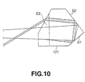
- that part of the input/output plane S3 from which the deep-ultraviolet laser beam is emitted may be inclined, as shown in FIG. 10, at almost a Brewster angle to the axis of the deep-ultraviolet laser beam.
- the nonlinear optical element 101 has a more complex shape, rendering it difficult to manufacture the nonlinear optical element 101. Nevertheless, it is possible to decrease the reflection loss in the deep-ultraviolet laser beam, which occurs in the nonlinear optical element 101.
- the sides of the nonlinear optical element 101 be left unpolished.
- the sides of the element 101 should remain in sand-blasted state.
- the sides of the element 101 can function as diffusion panels, diffusing the deep-ultraviolet laser beam.
- the light beam of the ultraviolet region can be uniformly applied to the light-receiving surface of the photodetector. Since the ultraviolet beam is not focused at a limited part of the light-receiving surface of the photodetector, it would not lower the sensitivity of the photodetector.
- the green laser beam traveling as an extraordinary ray in the nonlinear optical element 101 can be utilized as will be explained.
- the green laser beam enters the nonlinear optical element 101 it has a component, though small, which will become an extraordinary ray. This component amount is only about 0.15% of the green laser beam if the nonlinear optical element 101 has an apex angle ⁇ 0 of 88.5° as mentioned above.
- the nonlinear optical element 101 Nevertheless, it travels as an extraordinary ray in the nonlinear optical element 101, along almost the same path as the deep-ultraviolet laser beam, and emerges from the element 101, at almost the same position as the deep-ultraviolet laser beam.
- the component of the green laser beam emerges from the input/output plane S3 in a direction different from the direction in which the deep-ultraviolet laser beam is emitted from the plane S3. This is because the component, which travels as an extraordinary ray in the element 101, is refracted less than the deep-ultraviolet laser beam.
- a photodetector may be arranged on the path of the green laser beam emitter from the element 101 in a direction different from the direction in which the deep-ultraviolet laser beam is emitted from the element 101.
- the photodetector may then detect the intensity of the green laser beam. In other words, it can monitor the intensity . of the green laser beam applied as fundamental wave to the deep-ultraviolet laser beam-generating section 20.
- the laser beam-generating apparatus 1 that is designed to generate a deep-ultraviolet laser beam having the wavelength of 266 nm.
- the present invention is not limited to the apparatus 1. It can be applied to any laser beam-generating apparatus that has a nonlinear optical element configured to perform wavelength conversion on an input beam and that generates a laser beam having a prescribed wavelength.
Landscapes
- Physics & Mathematics (AREA)
- Nonlinear Science (AREA)
- Optics & Photonics (AREA)
- Electromagnetism (AREA)
- General Physics & Mathematics (AREA)
- Engineering & Computer Science (AREA)
- Plasma & Fusion (AREA)
- Optical Modulation, Optical Deflection, Nonlinear Optics, Optical Demodulation, Optical Logic Elements (AREA)
- Lasers (AREA)
- Semiconductor Lasers (AREA)
Applications Claiming Priority (2)
| Application Number | Priority Date | Filing Date | Title |
|---|---|---|---|
| JP2000241787A JP2002055369A (ja) | 2000-08-09 | 2000-08-09 | レーザ光発生装置 |
| JP2000241787 | 2000-08-09 |
Publications (3)
| Publication Number | Publication Date |
|---|---|
| EP1180717A2 true EP1180717A2 (fr) | 2002-02-20 |
| EP1180717A3 EP1180717A3 (fr) | 2004-10-06 |
| EP1180717B1 EP1180717B1 (fr) | 2008-05-07 |
Family
ID=18732926
Family Applications (1)
| Application Number | Title | Priority Date | Filing Date |
|---|---|---|---|
| EP01118607A Expired - Lifetime EP1180717B1 (fr) | 2000-08-09 | 2001-08-02 | Générateur d'harmoniques optiques |
Country Status (6)
| Country | Link |
|---|---|
| US (1) | US6658029B2 (fr) |
| EP (1) | EP1180717B1 (fr) |
| JP (1) | JP2002055369A (fr) |
| KR (1) | KR100825655B1 (fr) |
| CN (1) | CN1218449C (fr) |
| DE (1) | DE60133862D1 (fr) |
Families Citing this family (11)
| Publication number | Priority date | Publication date | Assignee | Title |
|---|---|---|---|---|
| JP4211399B2 (ja) * | 2003-01-10 | 2009-01-21 | 三菱マテリアル株式会社 | 波長変換素子および基本波処理方法 |
| US7646546B1 (en) * | 2005-06-10 | 2010-01-12 | Cvi Laser, Llc | Anamorphic optical system providing a highly polarized laser output |
| CN101253659B (zh) * | 2005-08-29 | 2010-12-29 | 松下电器产业株式会社 | 光纤激光器及光学装置 |
| JP5122542B2 (ja) * | 2009-09-15 | 2013-01-16 | シャープ株式会社 | 発光装置、照明装置および光検知器 |
| US20120022616A1 (en) | 2010-07-21 | 2012-01-26 | Med-El Elektromedizinische Geraete Gmbh | Vestibular Implant System with Internal and External Motion Sensors |
| JP5232884B2 (ja) * | 2011-02-25 | 2013-07-10 | 昭和オプトロニクス株式会社 | 紫外レーザ装置 |
| CN102809549A (zh) * | 2012-08-24 | 2012-12-05 | 北京爱尔达电子设备有限公司 | 一种同源双目标透射能见度仪用反射装置及使用方法 |
| EP3033613A4 (fr) * | 2013-08-15 | 2017-06-14 | Swinburne University of Technology | Appareil et procédé |
| CN110244498B (zh) * | 2018-05-09 | 2022-04-22 | 中国科学院理化技术研究所 | 非线性频率转换晶体 |
| KR102374247B1 (ko) * | 2021-05-12 | 2022-03-15 | (재)한국나노기술원 | 고효율 uv-c 발광 장치 |
| CN120237517A (zh) * | 2025-04-02 | 2025-07-01 | 山西大学 | 一种全固态高功率连续波单频紫外激光器 |
Family Cites Families (4)
| Publication number | Priority date | Publication date | Assignee | Title |
|---|---|---|---|---|
| US4653056A (en) * | 1985-05-01 | 1987-03-24 | Spectra-Physics, Inc. | Nd-YAG laser |
| US4731787A (en) * | 1986-08-15 | 1988-03-15 | Board Of Trustees, Stanford University | Monolithic phasematched laser harmonic generator |
| KR100366699B1 (ko) * | 1996-06-10 | 2003-03-06 | 삼성전자 주식회사 | 내부 공진형 제2 고조파 발생 장치 |
| DE19818612B4 (de) * | 1998-04-20 | 2005-03-10 | Spectra Physics Gmbh | Verfahren und Vorrichtung zur Frequenzkonversion, insbesondere zur Frequenzverdopplung von Festfrequenzlasern |
-
2000
- 2000-08-09 JP JP2000241787A patent/JP2002055369A/ja not_active Abandoned
-
2001
- 2001-07-31 US US09/918,730 patent/US6658029B2/en not_active Expired - Fee Related
- 2001-08-02 DE DE60133862T patent/DE60133862D1/de not_active Expired - Fee Related
- 2001-08-02 EP EP01118607A patent/EP1180717B1/fr not_active Expired - Lifetime
- 2001-08-09 CN CN011245824A patent/CN1218449C/zh not_active Expired - Fee Related
- 2001-08-09 KR KR1020010048007A patent/KR100825655B1/ko not_active Expired - Fee Related
Also Published As
| Publication number | Publication date |
|---|---|
| CN1337766A (zh) | 2002-02-27 |
| KR20020013453A (ko) | 2002-02-20 |
| EP1180717A3 (fr) | 2004-10-06 |
| KR100825655B1 (ko) | 2008-04-29 |
| CN1218449C (zh) | 2005-09-07 |
| DE60133862D1 (de) | 2008-06-19 |
| US6658029B2 (en) | 2003-12-02 |
| EP1180717B1 (fr) | 2008-05-07 |
| US20020104971A1 (en) | 2002-08-08 |
| JP2002055369A (ja) | 2002-02-20 |
Similar Documents
| Publication | Publication Date | Title |
|---|---|---|
| US7535938B2 (en) | Low-noise monolithic microchip lasers capable of producing wavelengths ranging from IR to UV based on efficient and cost-effective frequency conversion | |
| US5321718A (en) | Frequency converted laser diode and lens system therefor | |
| US5181211A (en) | Eye-safe laser system | |
| US10283926B2 (en) | Laser system with highly efficient, single-pass, harmonic generator with round output beam | |
| US7027209B2 (en) | Optical resonant frequency converter | |
| US9405169B2 (en) | Frequency-converted light source | |
| KR100272196B1 (ko) | 레이저 광 발생장치 | |
| US5227911A (en) | Monolithic total internal reflection optical resonator | |
| US6658029B2 (en) | Laser beam-generating apparatus | |
| US5781571A (en) | Optical parametric oscillator with porro prism cavity | |
| JP2501302B2 (ja) | レ―ザ―装置および方法 | |
| US5197072A (en) | Optical wavelength converting device, and laser diode pumped solid laser | |
| US6647033B1 (en) | Optical parametric osicllators with improved beam quality | |
| JP2000162656A (ja) | 半導体デバイス | |
| US6647034B1 (en) | Method to improve optical parametric oscillator beam quality | |
| US6775054B1 (en) | Image-rotating, 4-mirror, ring optical parametric oscillator | |
| EP0957546A2 (fr) | Laser à solide et amplificateur pour ledit laser | |
| CN101383477A (zh) | 激光二次谐波发生装置 | |
| JPH1055005A (ja) | レーザ光発生装置 | |
| US6384973B1 (en) | Convex brewster-cut crystal for nonlinear frequency conversion | |
| US20060221434A1 (en) | Laser oscillation device | |
| JP3322724B2 (ja) | 光パラメトリック発振器 | |
| JPS63185084A (ja) | 光波長可変レ−ザ装置 | |
| JP2021132127A (ja) | 半導体レーザ励起固体レーザ | |
| JPH0645680A (ja) | 固体レーザ装置 |
Legal Events
| Date | Code | Title | Description |
|---|---|---|---|
| PUAI | Public reference made under article 153(3) epc to a published international application that has entered the european phase |
Free format text: ORIGINAL CODE: 0009012 |
|
| AK | Designated contracting states |
Kind code of ref document: A2 Designated state(s): AT BE CH CY DE DK ES FI FR GB GR IE IT LI LU MC NL PT SE TR |
|
| AX | Request for extension of the european patent |
Free format text: AL;LT;LV;MK;RO;SI |
|
| PUAL | Search report despatched |
Free format text: ORIGINAL CODE: 0009013 |
|
| AK | Designated contracting states |
Kind code of ref document: A3 Designated state(s): AT BE CH CY DE DK ES FI FR GB GR IE IT LI LU MC NL PT SE TR |
|
| AX | Request for extension of the european patent |
Extension state: AL LT LV MK RO SI |
|
| 17P | Request for examination filed |
Effective date: 20050309 |
|
| AKX | Designation fees paid |
Designated state(s): DE FR GB |
|
| 17Q | First examination report despatched |
Effective date: 20050610 |
|
| GRAP | Despatch of communication of intention to grant a patent |
Free format text: ORIGINAL CODE: EPIDOSNIGR1 |
|
| GRAS | Grant fee paid |
Free format text: ORIGINAL CODE: EPIDOSNIGR3 |
|
| GRAA | (expected) grant |
Free format text: ORIGINAL CODE: 0009210 |
|
| AK | Designated contracting states |
Kind code of ref document: B1 Designated state(s): DE FR GB |
|
| REG | Reference to a national code |
Ref country code: GB Ref legal event code: FG4D |
|
| REF | Corresponds to: |
Ref document number: 60133862 Country of ref document: DE Date of ref document: 20080619 Kind code of ref document: P |
|
| PGFP | Annual fee paid to national office [announced via postgrant information from national office to epo] |
Ref country code: DE Payment date: 20080814 Year of fee payment: 8 |
|
| PGFP | Annual fee paid to national office [announced via postgrant information from national office to epo] |
Ref country code: FR Payment date: 20080818 Year of fee payment: 8 |
|
| PGFP | Annual fee paid to national office [announced via postgrant information from national office to epo] |
Ref country code: GB Payment date: 20080813 Year of fee payment: 8 |
|
| PLBE | No opposition filed within time limit |
Free format text: ORIGINAL CODE: 0009261 |
|
| STAA | Information on the status of an ep patent application or granted ep patent |
Free format text: STATUS: NO OPPOSITION FILED WITHIN TIME LIMIT |
|
| 26N | No opposition filed |
Effective date: 20090210 |
|
| GBPC | Gb: european patent ceased through non-payment of renewal fee |
Effective date: 20090802 |
|
| REG | Reference to a national code |
Ref country code: FR Ref legal event code: ST Effective date: 20100430 |
|
| PG25 | Lapsed in a contracting state [announced via postgrant information from national office to epo] |
Ref country code: FR Free format text: LAPSE BECAUSE OF NON-PAYMENT OF DUE FEES Effective date: 20090831 Ref country code: DE Free format text: LAPSE BECAUSE OF NON-PAYMENT OF DUE FEES Effective date: 20100302 |
|
| PG25 | Lapsed in a contracting state [announced via postgrant information from national office to epo] |
Ref country code: GB Free format text: LAPSE BECAUSE OF NON-PAYMENT OF DUE FEES Effective date: 20090802 |