EP1182177B2 - Elément d'isolation , Procédé et installation pour la fabrication de matériaux isolants ainsi que nappe d'enveloppe en fibres minérales - Google Patents
Elément d'isolation , Procédé et installation pour la fabrication de matériaux isolants ainsi que nappe d'enveloppe en fibres minérales Download PDFInfo
- Publication number
- EP1182177B2 EP1182177B2 EP01117083.4A EP01117083A EP1182177B2 EP 1182177 B2 EP1182177 B2 EP 1182177B2 EP 01117083 A EP01117083 A EP 01117083A EP 1182177 B2 EP1182177 B2 EP 1182177B2
- Authority
- EP
- European Patent Office
- Prior art keywords
- binder
- process according
- increased
- binder content
- area
- Prior art date
- Legal status (The legal status is an assumption and is not a legal conclusion. Google has not performed a legal analysis and makes no representation as to the accuracy of the status listed.)
- Expired - Lifetime
Links
- 238000000034 method Methods 0.000 title claims description 49
- 238000004519 manufacturing process Methods 0.000 title abstract description 22
- 239000011810 insulating material Substances 0.000 title description 18
- 229910052500 inorganic mineral Inorganic materials 0.000 title 1
- 239000011707 mineral Substances 0.000 title 1
- 239000011230 binding agent Substances 0.000 claims abstract description 190
- 239000000835 fiber Substances 0.000 claims abstract description 67
- 239000002557 mineral fiber Substances 0.000 claims abstract description 60
- 230000008569 process Effects 0.000 claims description 29
- 239000011490 mineral wool Substances 0.000 claims description 28
- 239000000203 mixture Substances 0.000 claims description 17
- 229920001807 Urea-formaldehyde Polymers 0.000 claims description 8
- 230000002093 peripheral effect Effects 0.000 claims description 8
- LCDFWRDNEPDQBV-UHFFFAOYSA-N formaldehyde;phenol;urea Chemical compound O=C.NC(N)=O.OC1=CC=CC=C1 LCDFWRDNEPDQBV-UHFFFAOYSA-N 0.000 claims description 7
- 239000000126 substance Substances 0.000 claims description 7
- 239000002114 nanocomposite Substances 0.000 claims description 6
- 239000002480 mineral oil Substances 0.000 claims description 5
- 229920000877 Melamine resin Polymers 0.000 claims description 4
- 239000011521 glass Substances 0.000 claims description 4
- NIXOWILDQLNWCW-UHFFFAOYSA-M Acrylate Chemical compound [O-]C(=O)C=C NIXOWILDQLNWCW-UHFFFAOYSA-M 0.000 claims description 3
- 239000004640 Melamine resin Substances 0.000 claims description 3
- 230000002209 hydrophobic effect Effects 0.000 claims description 3
- 238000005470 impregnation Methods 0.000 claims description 3
- 229920000728 polyester Polymers 0.000 claims description 3
- 229920002689 polyvinyl acetate Polymers 0.000 claims description 3
- 235000019353 potassium silicate Nutrition 0.000 claims description 3
- 229920005989 resin Polymers 0.000 claims description 3
- 239000011347 resin Substances 0.000 claims description 3
- RMAQACBXLXPBSY-UHFFFAOYSA-N silicic acid Chemical compound O[Si](O)(O)O RMAQACBXLXPBSY-UHFFFAOYSA-N 0.000 claims description 3
- 229920002050 silicone resin Polymers 0.000 claims description 3
- NTHWMYGWWRZVTN-UHFFFAOYSA-N sodium silicate Chemical compound [Na+].[Na+].[O-][Si]([O-])=O NTHWMYGWWRZVTN-UHFFFAOYSA-N 0.000 claims description 3
- 239000010409 thin film Substances 0.000 claims description 3
- 238000009736 wetting Methods 0.000 claims description 3
- 150000001298 alcohols Chemical class 0.000 claims description 2
- 125000001931 aliphatic group Chemical group 0.000 claims description 2
- 238000000151 deposition Methods 0.000 claims description 2
- 239000002694 phosphate binding agent Substances 0.000 claims description 2
- 239000004094 surface-active agent Substances 0.000 claims description 2
- 239000004753 textile Substances 0.000 claims description 2
- 229920001169 thermoplastic Polymers 0.000 claims description 2
- 239000004416 thermosoftening plastic Substances 0.000 claims description 2
- 235000015112 vegetable and seed oil Nutrition 0.000 claims description 2
- 239000008158 vegetable oil Substances 0.000 claims description 2
- VYPSYNLAJGMNEJ-UHFFFAOYSA-N Silicium dioxide Chemical compound O=[Si]=O VYPSYNLAJGMNEJ-UHFFFAOYSA-N 0.000 claims 2
- 235000019463 artificial additive Nutrition 0.000 claims 2
- 101100129500 Caenorhabditis elegans max-2 gene Proteins 0.000 claims 1
- 239000004890 Hydrophobing Agent Substances 0.000 claims 1
- 229910019142 PO4 Inorganic materials 0.000 claims 1
- 239000003921 oil Substances 0.000 claims 1
- 235000019198 oils Nutrition 0.000 claims 1
- 239000010452 phosphate Substances 0.000 claims 1
- NBIIXXVUZAFLBC-UHFFFAOYSA-K phosphate Chemical compound [O-]P([O-])([O-])=O NBIIXXVUZAFLBC-UHFFFAOYSA-K 0.000 claims 1
- 235000021317 phosphate Nutrition 0.000 claims 1
- 238000004064 recycling Methods 0.000 claims 1
- 239000000377 silicon dioxide Substances 0.000 claims 1
- 238000005507 spraying Methods 0.000 claims 1
- 230000008016 vaporization Effects 0.000 claims 1
- 238000009834 vaporization Methods 0.000 claims 1
- 239000000155 melt Substances 0.000 abstract description 15
- 239000000463 material Substances 0.000 abstract description 4
- BPQQTUXANYXVAA-UHFFFAOYSA-N Orthosilicate Chemical compound [O-][Si]([O-])([O-])[O-] BPQQTUXANYXVAA-UHFFFAOYSA-N 0.000 abstract description 3
- 230000008018 melting Effects 0.000 abstract description 3
- 238000002844 melting Methods 0.000 abstract description 3
- 230000002776 aggregation Effects 0.000 abstract description 2
- 238000007789 sealing Methods 0.000 abstract 3
- 229920001410 Microfiber Polymers 0.000 abstract 1
- 238000004220 aggregation Methods 0.000 abstract 1
- 239000003658 microfiber Substances 0.000 abstract 1
- 238000009413 insulation Methods 0.000 description 23
- 238000007906 compression Methods 0.000 description 13
- 230000006835 compression Effects 0.000 description 13
- 239000003365 glass fiber Substances 0.000 description 11
- 238000003860 storage Methods 0.000 description 5
- XLYOFNOQVPJJNP-UHFFFAOYSA-N water Substances O XLYOFNOQVPJJNP-UHFFFAOYSA-N 0.000 description 5
- 239000002245 particle Substances 0.000 description 4
- 238000005096 rolling process Methods 0.000 description 4
- 238000005336 cracking Methods 0.000 description 3
- 238000001704 evaporation Methods 0.000 description 3
- 230000008020 evaporation Effects 0.000 description 3
- 239000011888 foil Substances 0.000 description 3
- 239000011491 glass wool Substances 0.000 description 3
- 238000009434 installation Methods 0.000 description 3
- 239000004745 nonwoven fabric Substances 0.000 description 3
- 230000009471 action Effects 0.000 description 2
- 239000000443 aerosol Substances 0.000 description 2
- 230000015572 biosynthetic process Effects 0.000 description 2
- 239000003795 chemical substances by application Substances 0.000 description 2
- 238000010276 construction Methods 0.000 description 2
- 238000011109 contamination Methods 0.000 description 2
- 238000001816 cooling Methods 0.000 description 2
- 238000011161 development Methods 0.000 description 2
- 238000009826 distribution Methods 0.000 description 2
- 230000000694 effects Effects 0.000 description 2
- 238000005516 engineering process Methods 0.000 description 2
- 239000000243 solution Substances 0.000 description 2
- 229920001187 thermosetting polymer Polymers 0.000 description 2
- 230000003313 weakening effect Effects 0.000 description 2
- OYPRJOBELJOOCE-UHFFFAOYSA-N Calcium Chemical compound [Ca] OYPRJOBELJOOCE-UHFFFAOYSA-N 0.000 description 1
- 239000004593 Epoxy Substances 0.000 description 1
- 229910004298 SiO 2 Inorganic materials 0.000 description 1
- 239000013543 active substance Substances 0.000 description 1
- 238000005054 agglomeration Methods 0.000 description 1
- XAGFODPZIPBFFR-UHFFFAOYSA-N aluminium Chemical compound [Al] XAGFODPZIPBFFR-UHFFFAOYSA-N 0.000 description 1
- 229910052782 aluminium Inorganic materials 0.000 description 1
- 239000007864 aqueous solution Substances 0.000 description 1
- 239000002969 artificial stone Substances 0.000 description 1
- 230000004888 barrier function Effects 0.000 description 1
- 239000011324 bead Substances 0.000 description 1
- 238000009835 boiling Methods 0.000 description 1
- 229910052810 boron oxide Inorganic materials 0.000 description 1
- 239000011575 calcium Substances 0.000 description 1
- 229910052791 calcium Inorganic materials 0.000 description 1
- 235000012255 calcium oxide Nutrition 0.000 description 1
- 238000004364 calculation method Methods 0.000 description 1
- 239000012876 carrier material Substances 0.000 description 1
- 230000008859 change Effects 0.000 description 1
- 239000011248 coating agent Substances 0.000 description 1
- 238000000576 coating method Methods 0.000 description 1
- 230000001427 coherent effect Effects 0.000 description 1
- 238000005056 compaction Methods 0.000 description 1
- 230000000295 complement effect Effects 0.000 description 1
- 239000000470 constituent Substances 0.000 description 1
- 238000010924 continuous production Methods 0.000 description 1
- 239000000498 cooling water Substances 0.000 description 1
- 230000007423 decrease Effects 0.000 description 1
- 230000001419 dependent effect Effects 0.000 description 1
- 230000004069 differentiation Effects 0.000 description 1
- 239000006185 dispersion Substances 0.000 description 1
- 239000000428 dust Substances 0.000 description 1
- 239000000839 emulsion Substances 0.000 description 1
- 230000007613 environmental effect Effects 0.000 description 1
- 238000007667 floating Methods 0.000 description 1
- -1 for example Substances 0.000 description 1
- 238000009472 formulation Methods 0.000 description 1
- 238000000265 homogenisation Methods 0.000 description 1
- 238000010348 incorporation Methods 0.000 description 1
- UQSXHKLRYXJYBZ-UHFFFAOYSA-N iron oxide Inorganic materials [Fe]=O UQSXHKLRYXJYBZ-UHFFFAOYSA-N 0.000 description 1
- 235000013980 iron oxide Nutrition 0.000 description 1
- VBMVTYDPPZVILR-UHFFFAOYSA-N iron(2+);oxygen(2-) Chemical class [O-2].[Fe+2] VBMVTYDPPZVILR-UHFFFAOYSA-N 0.000 description 1
- 235000012245 magnesium oxide Nutrition 0.000 description 1
- AXZKOIWUVFPNLO-UHFFFAOYSA-N magnesium;oxygen(2-) Chemical class [O-2].[Mg+2] AXZKOIWUVFPNLO-UHFFFAOYSA-N 0.000 description 1
- 238000012423 maintenance Methods 0.000 description 1
- 235000010446 mineral oil Nutrition 0.000 description 1
- 238000012986 modification Methods 0.000 description 1
- 230000004048 modification Effects 0.000 description 1
- 230000007935 neutral effect Effects 0.000 description 1
- MOWNZPNSYMGTMD-UHFFFAOYSA-N oxidoboron Chemical class O=[B] MOWNZPNSYMGTMD-UHFFFAOYSA-N 0.000 description 1
- 238000012856 packing Methods 0.000 description 1
- 239000003973 paint Substances 0.000 description 1
- 239000000123 paper Substances 0.000 description 1
- ISWSIDIOOBJBQZ-UHFFFAOYSA-N phenol group Chemical group C1(=CC=CC=C1)O ISWSIDIOOBJBQZ-UHFFFAOYSA-N 0.000 description 1
- 239000004033 plastic Substances 0.000 description 1
- 229920003023 plastic Polymers 0.000 description 1
- 239000004597 plastic additive Substances 0.000 description 1
- 229920001225 polyester resin Polymers 0.000 description 1
- 239000004645 polyester resin Substances 0.000 description 1
- 238000011417 postcuring Methods 0.000 description 1
- 239000002244 precipitate Substances 0.000 description 1
- 239000000047 product Substances 0.000 description 1
- 230000002035 prolonged effect Effects 0.000 description 1
- 238000010791 quenching Methods 0.000 description 1
- 230000000171 quenching effect Effects 0.000 description 1
- 239000002994 raw material Substances 0.000 description 1
- 230000035484 reaction time Effects 0.000 description 1
- 239000005871 repellent Substances 0.000 description 1
- 230000002940 repellent Effects 0.000 description 1
- 230000000452 restraining effect Effects 0.000 description 1
- 238000000926 separation method Methods 0.000 description 1
- 238000007493 shaping process Methods 0.000 description 1
- 150000004756 silanes Chemical class 0.000 description 1
- 239000003238 silicate melt Substances 0.000 description 1
- 239000002904 solvent Substances 0.000 description 1
- 239000007858 starting material Substances 0.000 description 1
- 229920003002 synthetic resin Polymers 0.000 description 1
- 239000000057 synthetic resin Substances 0.000 description 1
- 238000012546 transfer Methods 0.000 description 1
- 238000007740 vapor deposition Methods 0.000 description 1
- 239000002699 waste material Substances 0.000 description 1
- 239000003232 water-soluble binding agent Substances 0.000 description 1
- 238000004804 winding Methods 0.000 description 1
Images


Classifications
-
- D—TEXTILES; PAPER
- D04—BRAIDING; LACE-MAKING; KNITTING; TRIMMINGS; NON-WOVEN FABRICS
- D04H—MAKING TEXTILE FABRICS, e.g. FROM FIBRES OR FILAMENTARY MATERIAL; FABRICS MADE BY SUCH PROCESSES OR APPARATUS, e.g. FELTS, NON-WOVEN FABRICS; COTTON-WOOL; WADDING ; NON-WOVEN FABRICS FROM STAPLE FIBRES, FILAMENTS OR YARNS, BONDED WITH AT LEAST ONE WEB-LIKE MATERIAL DURING THEIR CONSOLIDATION
- D04H1/00—Non-woven fabrics formed wholly or mainly of staple fibres or like relatively short fibres
- D04H1/40—Non-woven fabrics formed wholly or mainly of staple fibres or like relatively short fibres from fleeces or layers composed of fibres without existing or potential cohesive properties
- D04H1/42—Non-woven fabrics formed wholly or mainly of staple fibres or like relatively short fibres from fleeces or layers composed of fibres without existing or potential cohesive properties characterised by the use of certain kinds of fibres insofar as this use has no preponderant influence on the consolidation of the fleece
- D04H1/4209—Inorganic fibres
- D04H1/4218—Glass fibres
- D04H1/4226—Glass fibres characterised by the apparatus for manufacturing the glass fleece
-
- D—TEXTILES; PAPER
- D04—BRAIDING; LACE-MAKING; KNITTING; TRIMMINGS; NON-WOVEN FABRICS
- D04H—MAKING TEXTILE FABRICS, e.g. FROM FIBRES OR FILAMENTARY MATERIAL; FABRICS MADE BY SUCH PROCESSES OR APPARATUS, e.g. FELTS, NON-WOVEN FABRICS; COTTON-WOOL; WADDING ; NON-WOVEN FABRICS FROM STAPLE FIBRES, FILAMENTS OR YARNS, BONDED WITH AT LEAST ONE WEB-LIKE MATERIAL DURING THEIR CONSOLIDATION
- D04H1/00—Non-woven fabrics formed wholly or mainly of staple fibres or like relatively short fibres
- D04H1/40—Non-woven fabrics formed wholly or mainly of staple fibres or like relatively short fibres from fleeces or layers composed of fibres without existing or potential cohesive properties
- D04H1/42—Non-woven fabrics formed wholly or mainly of staple fibres or like relatively short fibres from fleeces or layers composed of fibres without existing or potential cohesive properties characterised by the use of certain kinds of fibres insofar as this use has no preponderant influence on the consolidation of the fleece
- D04H1/4382—Stretched reticular film fibres; Composite fibres; Mixed fibres; Ultrafine fibres; Fibres for artificial leather
- D04H1/43835—Mixed fibres, e.g. at least two chemically different fibres or fibre blends
-
- C—CHEMISTRY; METALLURGY
- C03—GLASS; MINERAL OR SLAG WOOL
- C03C—CHEMICAL COMPOSITION OF GLASSES, GLAZES OR VITREOUS ENAMELS; SURFACE TREATMENT OF GLASS; SURFACE TREATMENT OF FIBRES OR FILAMENTS MADE FROM GLASS, MINERALS OR SLAGS; JOINING GLASS TO GLASS OR OTHER MATERIALS
- C03C25/00—Surface treatment of fibres or filaments made from glass, minerals or slags
- C03C25/10—Coating
- C03C25/12—General methods of coating; Devices therefor
-
- C—CHEMISTRY; METALLURGY
- C03—GLASS; MINERAL OR SLAG WOOL
- C03C—CHEMICAL COMPOSITION OF GLASSES, GLAZES OR VITREOUS ENAMELS; SURFACE TREATMENT OF GLASS; SURFACE TREATMENT OF FIBRES OR FILAMENTS MADE FROM GLASS, MINERALS OR SLAGS; JOINING GLASS TO GLASS OR OTHER MATERIALS
- C03C25/00—Surface treatment of fibres or filaments made from glass, minerals or slags
- C03C25/10—Coating
- C03C25/12—General methods of coating; Devices therefor
- C03C25/14—Spraying
- C03C25/146—Spraying onto fibres in suspension in a gaseous medium
-
- C—CHEMISTRY; METALLURGY
- C03—GLASS; MINERAL OR SLAG WOOL
- C03C—CHEMICAL COMPOSITION OF GLASSES, GLAZES OR VITREOUS ENAMELS; SURFACE TREATMENT OF GLASS; SURFACE TREATMENT OF FIBRES OR FILAMENTS MADE FROM GLASS, MINERALS OR SLAGS; JOINING GLASS TO GLASS OR OTHER MATERIALS
- C03C25/00—Surface treatment of fibres or filaments made from glass, minerals or slags
- C03C25/10—Coating
- C03C25/24—Coatings containing organic materials
- C03C25/26—Macromolecular compounds or prepolymers
-
- D—TEXTILES; PAPER
- D04—BRAIDING; LACE-MAKING; KNITTING; TRIMMINGS; NON-WOVEN FABRICS
- D04H—MAKING TEXTILE FABRICS, e.g. FROM FIBRES OR FILAMENTARY MATERIAL; FABRICS MADE BY SUCH PROCESSES OR APPARATUS, e.g. FELTS, NON-WOVEN FABRICS; COTTON-WOOL; WADDING ; NON-WOVEN FABRICS FROM STAPLE FIBRES, FILAMENTS OR YARNS, BONDED WITH AT LEAST ONE WEB-LIKE MATERIAL DURING THEIR CONSOLIDATION
- D04H1/00—Non-woven fabrics formed wholly or mainly of staple fibres or like relatively short fibres
- D04H1/40—Non-woven fabrics formed wholly or mainly of staple fibres or like relatively short fibres from fleeces or layers composed of fibres without existing or potential cohesive properties
- D04H1/42—Non-woven fabrics formed wholly or mainly of staple fibres or like relatively short fibres from fleeces or layers composed of fibres without existing or potential cohesive properties characterised by the use of certain kinds of fibres insofar as this use has no preponderant influence on the consolidation of the fleece
- D04H1/4209—Inorganic fibres
-
- D—TEXTILES; PAPER
- D04—BRAIDING; LACE-MAKING; KNITTING; TRIMMINGS; NON-WOVEN FABRICS
- D04H—MAKING TEXTILE FABRICS, e.g. FROM FIBRES OR FILAMENTARY MATERIAL; FABRICS MADE BY SUCH PROCESSES OR APPARATUS, e.g. FELTS, NON-WOVEN FABRICS; COTTON-WOOL; WADDING ; NON-WOVEN FABRICS FROM STAPLE FIBRES, FILAMENTS OR YARNS, BONDED WITH AT LEAST ONE WEB-LIKE MATERIAL DURING THEIR CONSOLIDATION
- D04H1/00—Non-woven fabrics formed wholly or mainly of staple fibres or like relatively short fibres
- D04H1/40—Non-woven fabrics formed wholly or mainly of staple fibres or like relatively short fibres from fleeces or layers composed of fibres without existing or potential cohesive properties
- D04H1/42—Non-woven fabrics formed wholly or mainly of staple fibres or like relatively short fibres from fleeces or layers composed of fibres without existing or potential cohesive properties characterised by the use of certain kinds of fibres insofar as this use has no preponderant influence on the consolidation of the fleece
- D04H1/4209—Inorganic fibres
- D04H1/4218—Glass fibres
-
- D—TEXTILES; PAPER
- D04—BRAIDING; LACE-MAKING; KNITTING; TRIMMINGS; NON-WOVEN FABRICS
- D04H—MAKING TEXTILE FABRICS, e.g. FROM FIBRES OR FILAMENTARY MATERIAL; FABRICS MADE BY SUCH PROCESSES OR APPARATUS, e.g. FELTS, NON-WOVEN FABRICS; COTTON-WOOL; WADDING ; NON-WOVEN FABRICS FROM STAPLE FIBRES, FILAMENTS OR YARNS, BONDED WITH AT LEAST ONE WEB-LIKE MATERIAL DURING THEIR CONSOLIDATION
- D04H1/00—Non-woven fabrics formed wholly or mainly of staple fibres or like relatively short fibres
- D04H1/40—Non-woven fabrics formed wholly or mainly of staple fibres or like relatively short fibres from fleeces or layers composed of fibres without existing or potential cohesive properties
- D04H1/58—Non-woven fabrics formed wholly or mainly of staple fibres or like relatively short fibres from fleeces or layers composed of fibres without existing or potential cohesive properties by applying, incorporating or activating chemical or thermoplastic bonding agents, e.g. adhesives
- D04H1/587—Non-woven fabrics formed wholly or mainly of staple fibres or like relatively short fibres from fleeces or layers composed of fibres without existing or potential cohesive properties by applying, incorporating or activating chemical or thermoplastic bonding agents, e.g. adhesives characterised by the bonding agents used
-
- D—TEXTILES; PAPER
- D04—BRAIDING; LACE-MAKING; KNITTING; TRIMMINGS; NON-WOVEN FABRICS
- D04H—MAKING TEXTILE FABRICS, e.g. FROM FIBRES OR FILAMENTARY MATERIAL; FABRICS MADE BY SUCH PROCESSES OR APPARATUS, e.g. FELTS, NON-WOVEN FABRICS; COTTON-WOOL; WADDING ; NON-WOVEN FABRICS FROM STAPLE FIBRES, FILAMENTS OR YARNS, BONDED WITH AT LEAST ONE WEB-LIKE MATERIAL DURING THEIR CONSOLIDATION
- D04H1/00—Non-woven fabrics formed wholly or mainly of staple fibres or like relatively short fibres
- D04H1/40—Non-woven fabrics formed wholly or mainly of staple fibres or like relatively short fibres from fleeces or layers composed of fibres without existing or potential cohesive properties
- D04H1/58—Non-woven fabrics formed wholly or mainly of staple fibres or like relatively short fibres from fleeces or layers composed of fibres without existing or potential cohesive properties by applying, incorporating or activating chemical or thermoplastic bonding agents, e.g. adhesives
- D04H1/64—Non-woven fabrics formed wholly or mainly of staple fibres or like relatively short fibres from fleeces or layers composed of fibres without existing or potential cohesive properties by applying, incorporating or activating chemical or thermoplastic bonding agents, e.g. adhesives the bonding agent being applied in wet state, e.g. chemical agents in dispersions or solutions
- D04H1/645—Impregnation followed by a solidification process
-
- D—TEXTILES; PAPER
- D04—BRAIDING; LACE-MAKING; KNITTING; TRIMMINGS; NON-WOVEN FABRICS
- D04H—MAKING TEXTILE FABRICS, e.g. FROM FIBRES OR FILAMENTARY MATERIAL; FABRICS MADE BY SUCH PROCESSES OR APPARATUS, e.g. FELTS, NON-WOVEN FABRICS; COTTON-WOOL; WADDING ; NON-WOVEN FABRICS FROM STAPLE FIBRES, FILAMENTS OR YARNS, BONDED WITH AT LEAST ONE WEB-LIKE MATERIAL DURING THEIR CONSOLIDATION
- D04H1/00—Non-woven fabrics formed wholly or mainly of staple fibres or like relatively short fibres
- D04H1/40—Non-woven fabrics formed wholly or mainly of staple fibres or like relatively short fibres from fleeces or layers composed of fibres without existing or potential cohesive properties
- D04H1/58—Non-woven fabrics formed wholly or mainly of staple fibres or like relatively short fibres from fleeces or layers composed of fibres without existing or potential cohesive properties by applying, incorporating or activating chemical or thermoplastic bonding agents, e.g. adhesives
- D04H1/64—Non-woven fabrics formed wholly or mainly of staple fibres or like relatively short fibres from fleeces or layers composed of fibres without existing or potential cohesive properties by applying, incorporating or activating chemical or thermoplastic bonding agents, e.g. adhesives the bonding agent being applied in wet state, e.g. chemical agents in dispersions or solutions
- D04H1/655—Non-woven fabrics formed wholly or mainly of staple fibres or like relatively short fibres from fleeces or layers composed of fibres without existing or potential cohesive properties by applying, incorporating or activating chemical or thermoplastic bonding agents, e.g. adhesives the bonding agent being applied in wet state, e.g. chemical agents in dispersions or solutions characterised by the apparatus for applying bonding agents
-
- D—TEXTILES; PAPER
- D04—BRAIDING; LACE-MAKING; KNITTING; TRIMMINGS; NON-WOVEN FABRICS
- D04H—MAKING TEXTILE FABRICS, e.g. FROM FIBRES OR FILAMENTARY MATERIAL; FABRICS MADE BY SUCH PROCESSES OR APPARATUS, e.g. FELTS, NON-WOVEN FABRICS; COTTON-WOOL; WADDING ; NON-WOVEN FABRICS FROM STAPLE FIBRES, FILAMENTS OR YARNS, BONDED WITH AT LEAST ONE WEB-LIKE MATERIAL DURING THEIR CONSOLIDATION
- D04H1/00—Non-woven fabrics formed wholly or mainly of staple fibres or like relatively short fibres
- D04H1/70—Non-woven fabrics formed wholly or mainly of staple fibres or like relatively short fibres characterised by the method of forming fleeces or layers, e.g. reorientation of fibres
- D04H1/74—Non-woven fabrics formed wholly or mainly of staple fibres or like relatively short fibres characterised by the method of forming fleeces or layers, e.g. reorientation of fibres the fibres being orientated, e.g. in parallel (anisotropic fleeces)
-
- F—MECHANICAL ENGINEERING; LIGHTING; HEATING; WEAPONS; BLASTING
- F16—ENGINEERING ELEMENTS AND UNITS; GENERAL MEASURES FOR PRODUCING AND MAINTAINING EFFECTIVE FUNCTIONING OF MACHINES OR INSTALLATIONS; THERMAL INSULATION IN GENERAL
- F16L—PIPES; JOINTS OR FITTINGS FOR PIPES; SUPPORTS FOR PIPES, CABLES OR PROTECTIVE TUBING; MEANS FOR THERMAL INSULATION IN GENERAL
- F16L59/00—Thermal insulation in general
- F16L59/02—Shape or form of insulating materials, with or without coverings integral with the insulating materials
- F16L59/026—Mattresses, mats, blankets or the like
Definitions
- the invention relates to a method for producing an insulating element, in particular a rolling and windable insulation web of mineral fibers, preferably rockwool deposited in the mineral fibers with the addition of binders on a conveyor and the binder is then cured, the binder content of the mineral fibers after depositing is varied on the conveyor such that areas are formed over the width of the insulating element, which have an increased binder content.
- an insulating element in particular a rolling and windable insulation web of mineral fibers, preferably rockwool deposited in the mineral fibers with the addition of binders on a conveyor and the binder is then cured, the binder content of the mineral fibers after depositing is varied on the conveyor such that areas are formed over the width of the insulating element, which have an increased binder content.
- the invention relates to an insulating element made of binders bound mineral fibers, in particular rockwool fibers, preferably in the form of a windable, to be separated in individual plates insulation sheet of mineral fibers, consisting of a particular straight-sided body with two parallel to each other and spaced large surfaces and in particular perpendicular to the large surfaces extending side surfaces and end faces, which are also arranged at right angles and spaced from each other and aligned in parallel.
- binders bound mineral fibers in particular rockwool fibers, preferably in the form of a windable
- Insulation elements in the form of fiber insulation consist of natural organic fibers. Furthermore, mixtures of different types of fibers are possible with each other. The biggest market relevance have mineral wool insulation elements. Their essential elementary particles are vitreous solidified mineral fibers which are bound together by means of small amounts of binders. The aim is a pointwise connection of the individual mineral fibers in order to achieve an elastic-resilient behavior of a fiber mass to be formed and to obtain further.
- Typical binders are, for example, mixtures of thermoset-curing phenol-formaldehyde-urea resins, which are distributed in aqueous solution in the fiber mass. Phenol-formaldehyde-urea resins contain small amounts of adhesion-promoting substances. These are mostly silane compounds.
- combustible organic substances must be kept as low as possible in order to declare the insulating elements as non-combustible in the sense of DIN 4102 Part 1.
- phenolic resin-formaldehyde-urea resins other resins dissolved in water, water-alcohol and similar inexpensive solvents, such as melamine resin, epoxy, polyester resins can be used alone or in mixtures with each other.
- Mineral fibers are also bound with silica sol, which is incorporated in the form of nanoscale SiO 2 particles in a network of alkoysilanes.
- these inorganic binders are described, for example, in U.S. Pat WO 98/21266 described. Since further modifications exist in addition to the binders mentioned, such binders are also generally referred to below as nanocomposites or ormocers.
- the gelling time of these binders can be changed or adjusted according to the requirements of the manufacturing processes of the insulating elements in relatively wide areas. Depending on their proportions in the insulation elements between about 2 to 20% by mass results in a flexible to relatively brittle-hard bond.
- the curing time can be varied by a corresponding formulation of the composition within relatively wide limits.
- Mineral fibers are made by defibering silicate melts. The temperatures of these melts are above 1450 ° C to 1500 ° C. Commercially available glass and rock wool fibers are distinguished.
- the composition of the melt essentially determines the fiberization process used.
- the glasses which are suitable for glass fibers have relatively high contents of alkalis and boron oxides and therefore show a less pronounced dependence of the viscosity on the temperature.
- Insulating elements made of glass fibers are today produced industrially by means of the so-called TEL method. In this method, the melt is passed into a rotating bowl-like body whose side walls have holes. Through these holes, the melt emerges, which form due to the centrifugal forces in conjunction with a rapid cooling relatively long smooth, glassy solidified glass fibers.
- the glass fibers formed are passed down in a chute on an air-permeable conveyor belt and collected there according to the performance of the fiberizing aggregate and the speed of the conveyor belt to a closed layer of appropriate height.
- the packing density corresponds to the natural bulk density plus the contact pressure from the flow with the cooling and transport air.
- Such manufacturing methods are for example from the EP-A-0 375 486 .
- rockwool fibers The production of rockwool fibers is generally carried out on so-called cascade fiberizing machines. These consist mostly of three or four rollers that rotate at high circumferential speed about horizontal axes.
- the melt for the production of rockwool fibers is successively passed to the peripheral surfaces of the rolls. This dissolves particles from the melt that solidify in the form of rock wool fibers or non-fibrous, mostly spherical bodies. The remainder of the melt is directed to the next roller.
- the application of rock wool fibers reaches about 50% by mass.
- the average diameters of the rock wool fibers are about 2 - 3 microns and thus correspond to the diameter of the glass wool fibers.
- the non-fibrous particles remain about 30% in the form of very small beads in the pulp, while the coarser bodies can be separated by air classification.
- the quenching of the resulting rock wool fibers is done by evaporation of water and a release of heat energy to relatively large amounts of air. Because of the risk of fire and for cost and environmental reasons, water-soluble binder systems are used. A sudden evaporation produces very fine aerosols, which then precipitate on the surface of the rock wool fibers in the form of very fine droplets. This process must be done instatu-nascendi the mineral wool fibers. As soon as the mineral wool fibers aggregate into flakes in a turbulent air flow, uniform impregnation with binders, in particular with droplet-shaped substances, is no longer possible. In this case, the surface of each individual flake acts as a highly effective fine filter.
- binder addition occurs through the horizontal axes, which are hollow.
- the rock wool fibers are short and agitated, less than about 4.5% by weight of the conventional phenol-formaldehyde-urea resin mixture is required for their bonding, indicating a very good dispersion of the binder.
- the binder addition takes place below the fiberizing aggregate, so that with about 4 to 8% by mass significantly higher amounts of the binder have to be used.
- the distribution of binder levels in the pulp is not as uniform in glass fiber insulation as rock wool insulation.
- hydrophobic and dust-binding agents are added to the mineral fibers, which serve to impregnate the mineral fibers.
- these are, for example, high-boiling mineral oils which develop creep properties on the mineral fibers or oil-in-water emulsions which, due to the surface-active substances, cause a uniform wetting of the mineral fiber surfaces.
- mineral oil can be transported in cooling water, so that here also a sudden evaporation of water on the mineral fiber surfaces leads to the formation of very fine aerosols, which are then reflected by the binders on the mineral fiber surfaces.
- the goal in the production of mineral fiber insulation is to connect each individual fiber with the next pointwise. This is not fully possible in the current state of the art and the limitation of the proportion of binding organic substance in the insulating materials.
- the mineral fiber insulating materials contain high levels of unbound mineral fibers. As already shown in a rough calculation, significantly higher amounts of binder would have to be used to achieve the goal.
- An approximation to the desired goal consists in the fact that only a part of the mineral fibers are connected to each other and other mineral fibers are linked to them only because of their flake-like agglomerations.
- unbonded mineral fibers when present in the form of thin release layers in the pulp, are most unfavorable to strength development. The formation of these separation layers can not be prevented with the applied Aufsammlungstechnik.
- the collection technique causes fundamental structural differences between glass fibers and rock wool fibers.
- the longer and smoother glass fibers are mainly deposited horizontally and form a pronounced laminar structure. This has, for example, in the two planes running parallel to the large surfaces of the fiber mass, a significantly higher tensile strength than in the plane extending at right angles thereto. Accordingly, however, the heat transfer resistance in this direction is significantly higher than transverse to it.
- the rock wool fibers which are inclined at an angle from the outset, the directional dependence of the mechanical and thermal properties is less pronounced in comparison to the glass fibers.
- the individual shredding machines achieve outputs of more than 5 t / h. It is possible to arrange two or three fiberizing machines side by side and to collect the formed rock wool fibers in a collecting chamber.
- the rockwool fibers are collected in the thinnest coherent layers with basis weights of about 200 to 300 g / m 2 and transported away. This results in a so-called primary non-woven, which is laid by pendulum movements to a secondary nonwoven meandering over each other.
- this shuttle technique is movement of the primary web transverse to the subsequent direction of production. Individual primary nonwoven layers are therefore deposited in an oblique position to the large surfaces of the secondary nonwoven.
- an existing from the secondary nonwoven insulating material web consists of about 4 to 8 superimposed primary nonwoven layers.
- the technique of levitating primary nonwoven layers leads in comparison to the so-called direct Aufsammlungstechnik generally to a homogenization of the fiber mass distribution over the height and width and thus also to a largely uniform structure of the insulating material web.
- the surfaces of the primary nonwovens in the secondary nonwoven remain due to the reorientation of the individual mineral fibers and a weakening of the binding force.
- the unbound mineral fibers contribute to the weakening, the proportion of which is also relatively high in this fiberization technique.
- the unbound mineral fibers are deposited in shallow storage on the surfaces of the primary nonwovens and therefore find themselves layered in the secondary nonwoven again.
- the secondary nonwoven impregnated with binding and hydrophobizing agents is compressed to the desired thickness and bulk density in the further course of production by the pressure exerted on its large surfaces. If special structures are required, the secondary web can be upset both in the production longitudinal direction and across it. During forming, the binder must still remain tacky. The deformed secondary web is passed while maintaining the deformation forces in an oven in which hot air is sucked through the secondary web. As a result of the intense action of energy hardens the phenol-formaldehyde-urea resin mixture above about 220 ° C within a few minutes.
- Insulation elements are manufactured according to DIN 18165 Part 1 in the delivery forms plates, felt or mats.
- Plates are flat bodies made of bound mineral fibers.
- Felts also consist of bonded mineral fibers. They may be formed like the plates with or without coating of, for example, paper, aluminum foil, plastic foil, paint or the like. They are usually offered in rolled form.
- Mats are connected to carrier materials such as wire mesh, corrugated cardboard, nonwovens by needling or desertification. Mats can also be rolled up.
- insulation boards of mineral fibers are characterized by a certain inner strength or rigidity. According to DIN 18165 Part 1 only small deviations from the dimensions, in particular the thickness are allowed. Such insulation boards are, for example, wedged between the stand of wooden walls or clamped between the structural timber of beamed ceilings or inclined roof structures.
- Low-density and low-density insulation boards are rarely packed in compressed form, saving transport and storage space.
- the structure of individual insulation boards in the respective stack is usually irreversibly damaged, or reorientation of the fibers occurs with a longer storage time. In both cases, the nominal thickness and / or, for example, the original rigidity are then no longer achieved.
- Felts have lower binder contents than the insulation boards.
- the rigidity is low in all three spatial axes.
- Felts are compressed by up to 70% during reeling, i. an insulating felt, for example, with the nominal thickness of 100 mm is compressed up to 30 mm.
- an insulating felt for example, with the nominal thickness of 100 mm is compressed up to 30 mm.
- the felts are therefore made with excess thickness so that they reach the nominal thickness again after the compressive rolling or unrolling.
- the permitted deviations from the nominal thickness are significantly larger than in the case of plates, so that, in particular, positive variations in thickness do not restrict the usability.
- the felts are not suitable for self-locking installation between construction elements such as rafters. The attachment takes place with the aid of glued-on carrier foils which are fastened, for example, to the underside of the rafters.
- the felt is compressed at a density of 10 to 40 kg / m 3 , in particular 10 to 25 kg / m 3 when rolled in the ratio 1: 2.5.
- the rigidity of the sections is achieved by a binder content increased to 6 to 7% by mass.
- Rollable felts of rock wool fibers with densities of about 23 to 30 kg / m 3 are produced with binder contents of about 1.1 to 2.2% by mass. Despite these low bulk densities and low binder contents, the felts must be precompressed by up to approx. 70% before being rolled up. For the clamping installation of felts which can be divided into panels, these densities have from 30 to about 55 kg / m 3 and binder contents of about 2 to 2.5 mass%.
- a generic method is from the EP-A-0 374 112 known, deposited in the mineral fibers with the addition of binders on a conveyor and the binder is then cured. This results in an insulation web, which is then deposited meandering on another conveyor. Over the width, the insulating material web has a different binder content.
- the two fiber sections and the core are sandwiched one over the other, with an additional material being disposed in the constituents of the insulating element, which additional material is present in different concentrations in the individual components.
- the core has the highest concentration of the additional material, which may be, for example, a binder.
- the present invention seeks to provide an insulating element and a method for its production, which is easily wound gently, without the disadvantages described above, the insulating element has a high elasticity.
- mineral fibers in a middle zone with about 1.5 to about 5.0, preferably 2.0 to 2.5 mass% thermosetting, in thin films viscous deformable or zäh mecanicder synthetic resins, such as phenol-formaldehyde Urea resin mixtures or melamine resins, polyester or the like are added, while the mineral fibers are bound in the outer zones with a binder content of not more than 2% by mass, preferably between 0.8 and 1.5% by mass.
- a region of increased binder content is formed, which extends in the longitudinal direction of the insulating material web and is arranged in relation to the width of the insulating material web in the middle and preferably a width of up to 1/3 the total width of the insulating material web occupies.
- the region of increased binder content is introduced as a layer of uniform width in the insulating material web.
- the width of the region of increased binder content is varied at least in a plane parallel to the large surfaces.
- the roll-up capability of such an insulating element can also be improved by providing in the method according to the invention that the region of increased binder content is introduced into the insulating material web as a grid-like layer.
- the range of increased binder content may extend continuously in the longitudinal direction of the insulating material web. This area ends at some distance in front of the respective outer surfaces. As a result, a relatively soft edge surface is created, which allows a joint-tight fit, for example, between two adjacent rafters in the pitched roof area or adjacent insulation elements.
- the area of increased binder content is compressed in such a way that the bulk density in this area is increased in comparison to the other areas.
- a bulk density of between 28 and 40 kg / m 3 and in the other ranges a bulk density of between 20 and 32 kg / m 3 is produced.
- the difference between the bulk densities becomes smaller.
- a difference in the binder content exists between the areas of increased binder content and the areas of normal binder content.
- binder in the areas of increased binder content inorganic binder is provided according to a further feature of the invention that as binder in the areas of increased binder content inorganic binder , how nanocomposites and / or in particular brittle-brittle binder with short curing times, such as silica sol, water glass, phosphate binder and / or combinations or mixtures thereof is introduced with or without plastic additives.
- nanocomposites and / or in particular brittle-brittle binder with short curing times such as silica sol, water glass, phosphate binder and / or combinations or mixtures thereof is introduced with or without plastic additives.
- brittle-brittle binder with short curing times such as silica sol, water glass, phosphate binder and / or combinations or mixtures thereof is introduced with or without plastic additives.
- in the areas of increased binder content up to 15% by mass, in particular between 5% by mass and 10% by mass of inorganic binder is introduced.
- plastically deformable binders such as PVAC, acrylate and / or silicone resin and / or mixtures thereof are introduced.
- Such binders have considerable extensibility and can be deformed largely without cracking.
- the deformation should also be maintained for a while after unrolling, so that, for example, an arcuate shaping of the outer zone in the winding prevents falling out of felt sections from rafter fields. In the course of use, this deformation will regress. In this case, however, the maintenance of high restraining forces is not necessary because the cut-off from the felt plates is then usually held by a room-side vapor barrier or clothing in the rafter field.
- the insulating material web consists of a primary nonwoven with areas of increased binder content and areas with conventional, if appropriate. slightly increased binder content is produced, which is superimposed alternately.
- a larger amount of binder is added to the primary fibers forming mineral fibers at regular time intervals to form a primary nonwoven, alternately areas with elevated and usual, optionally. having slightly increased binder content.
- the primary nonwoven is then suspended in individual primary nonwoven layers which, when placed one above the other, form a secondary nonwoven.
- the ratio of the feed quantity of binders is changed via centrally arranged nozzles and via inner peripherally arranged nozzles with respect to outer peripherally arranged nozzles.
- the edges of the primary nonwoven layer are impregnated with a small amount of binder, as the area between the edges.
- binders preferably in different amounts
- nanocomposites can be introduced via the central nozzles and thermosetting and / or thermoplastic binders via the peripheral nozzles.
- hydrophobizing agents can be dispensed with here.
- the introduction of the binder may be symmetrical to the central axis of the fiberization machine or only on one side, for example, to make an enrichment preferably in an outer zone of the secondary nonwoven layer.
- Corresponding variations arise when connecting two or more fiberizing machines to a collection chamber. In many cases, this relatively small differentiation will be sufficient to achieve the desired product properties.
- a sharp distinction between the areas of increased binder content and the areas of normal or slightly increased binder content can be achieved in an insulating element in that the additional binder is additionally applied to the primary nonwoven layer.
- the application of the additional binder is preferably carried out at the output of a pendulum device in which the primary nonwoven is suspended in individual primary nonwoven layers to form a secondary nonwoven. In this way, an admission of the transport device and an associated contamination of the like with binders is prevented.
- An additional binding agent is applied in front of the pendulum device or additional binder is sprayed on to the secondary nonwoven following the floating of the primary nonwoven layers. In any case, a concentration of the binder in the primary nonwoven layers should be achieved in a certain width.
- the preferably sprayed-on binders must therefore contain wetting substances, such as alcohols and / or suitable surfactants, so that the fiber mass becomes capillary-active.
- wetting substances such as alcohols and / or suitable surfactants, so that the fiber mass becomes capillary-active.
- the effectiveness of these substances can be increased by not impregnating the pulp with water repellents until the binders have been applied. After the primary nonwoven layers have been deposited to form a secondary nonwoven, this is compressed and the binder is cured with heat under a corresponding pressure.
- the primary nonwoven layers will be partially or totally subjected to compression in order to form regions of increased apparent density in the primary nonwoven layers.
- the application of the additional binder may take the form of one or more strips in the running direction or transversely to the direction. A combination of both directions is possible.
- the above-mentioned compression of the primary nonwoven surface or stripwise The width and the number of pressure rollers preferably used for this purpose can be varied depending on the width of the primary web and the desired stiffening effect. Subsequent to the flat or strip-like compression of the primary web, the primary web is sprayed with additional binder. It is useful to arrange the binder nozzles following the pressure rollers in order to avoid contamination of the like by binders and thus also binder losses.
- binder-impregnated textile, glass, synthetic or natural fibers and also recycled fibers can be sprinkled onto the primary nonwoven.
- This fiber addition increases the tensile strength of the rollable insulating element generally or in certain zones.
- Recycled fibers from recovered Steinwolledämmimplantationn also cause a Roh Whyerhöhung and thus a more extensive stiffening of the produced insulating element.
- the recycled fibers can be arranged in one or more layers one above the other on the primary web. If several layers of recycled fibers are applied, this is preferably done in the form of relatively thin layers. Overall, it has proven to be advantageous to limit the amount of recycled fibers to a maximum of 25% by mass with respect to the total mass of the insulating element.
- An insulating element formed in this way is designed to be flexible and elastic in areas such that the insulating element can be wound compressed in a simple manner, wherein the insulating element substantially resumes its pre-compression form even after prolonged storage without further damage in the form of cracking occur. Furthermore, such an insulating element preferably divided into individual plates can be installed by clamping between adjacent components, such as rafters with sufficient rigidity and elasticity.
- a device in which nozzles are arranged on a circular arc, which circular arc surrounds the rollers of the fiberizing aggregate, wherein the nozzles guide the binder in a region in the longitudinal axis direction of the rollers up to a direction perpendicular to the longitudinal axis direction of the rollers in the direction on the discharged from the rollers mineral fibers.
- This device therefore allows the production of insulating elements made of mineral fibers with different characteristics with respect to the binder content.
- increased binder contents can be formed in all areas of the mineral fibers to be collected.
- the pendulum device is followed by at least one directed towards a large surface of the primary nonwoven nozzle for the application of binders to a range of increased binder content. Accordingly, it is provided in this device that the areas of increased binder content are formed only at a primary nonwoven layer.
- FIG. 1 illustrated apparatus for producing an insulating element 1, for example in the form of a windable mineral fiber felt has a melting furnace 2, are melted in the silicate starting material, such as glasses or natural or artificial stones.
- the melting furnace 2 has at its lower end an outlet 3, from which a melt 4 flows in the direction of a cascade fiber 5.
- the cascade fiber 5 consists of four rotatably driven rollers 6, which are arranged below the outlet 3, that the melt 4 impinges on the peripheral surface of the first roller 6, from where the melt 4 is partially frayed in a first step and not defibred Components of the melt 4 on a second underlying roller 6 passes. From this second roller 6, whose direction of rotation is oriented counter to the direction of rotation of the first roller 6, the further fibrillated melt 4 reaches the peripheral surface of the further below arranged third roller 6, the direction of rotation again coincides with the direction of rotation of the first roller 6.
- the further fibrillated melt 4 passes from the third roller 6 to the lowermost fourth roller 6, whose direction of rotation in turn coincides with the direction of rotation of the second roller 6.
- the rollers 6 have different diameters.
- the melt 4 is fiberized over the rollers 6, so that fibers 7 are formed with diameters and / or lengths in the micrometer range.
- the fibers 7 are wetted in a collection chamber, not shown, with binder to connect them together.
- the collection chamber comprises the cascade fiberizer 5.
- the connection of the mineral fibers 7 is to take place on a conveyor belt on which a primary nonwoven 9 is formed from the fibers 7 mixed with binders.
- the primary nonwoven 9 is then fed via a further conveyor belt 10 to a shuttle 11.
- the shuttle 11 consists of two conveyor belts, which are aligned parallel to each other and spaced apart. The distance between the conveyor belts of the shuttle 11 is variably adjustable.
- the two conveyor belts of the shuttle station 11 are reciprocated according to an arrow 12 to move the primary web 9 on a further conveyor belt 13 in primary nonwoven layers.
- the conveyor belt 13 in this case promotes in a direction according to arrow 14, which is aligned at right angles to the oscillating movement according to arrow 12.
- the primary nonwoven layers deposited on the conveyor belt 13 form a secondary nonwoven 15, which is fed to a compression device 16.
- the compression device 16 consists of above the secondary web 15 arranged pressure and compression rollers 17 and arranged below the secondary web 15 transport and compression rollers 18.
- the distance between compression and compression rollers 17 and the transport and compression rollers 18 is variably adjustable to over the Compression on the secondary web 15 to set the desired density of the insulating element 1.
- the secondary web 15 between the rollers 17 and 18 is also compressed in the transport direction and transversely thereto.
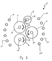
- FIG. 2 is the cascade fiber 5 according to FIG. 1 shown in detail. There are the rollers 6 can be seen. Arrows 19 indicate the direction of rotation of the rollers 6 about their respective central axis 20.
- the axes 20 are hollow and have nozzles which serve to add binders to the mineral fibers 7 formed from the melt 4.
- Arranged circular arc around the rollers 6 in the Kaskadenzermaschineer 5 peripheral nozzles 21, can also be applied to the mineral fibers 7 on the binder.
- different binders can be applied via the nozzles 20 arranged in the axes 20 and the nozzles 21.
- both the axes 20 and the nozzles 21 together or alternatively apply binder on the mineral fibers 7, for example, to wet mineral fibers 7 with a large amount of binder, which then forms areas 22 increased binder content in the insulating element 1.
- Corresponding areas 22 are in the FIGS. 4 to 6 shown, which will be described below.
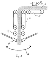
- FIG. 3 shows the shuttle 11 in a detailed side view. It can be seen that below the shuttle 11 additional pressure rollers 23 are arranged, which compress the primary web 9 on the output side of the shuttle 11 to a predetermined density. Below the pressure rollers 23 complementary nozzles 24 are provided for binder.
- the nozzles 24 extend substantially over the entire width of the primary web 9 and can be divided into individual nozzle sections, so that the task of binders on the primary web 9 is locally controllable.
- binder can be applied in regions, for example, to the central region of the primary nonwoven 9 via the nozzles 24, in order to produce a region 22 with an increased binder content there.
- the nozzles 24 are also like the pressure rollers 23 coupled to the conveyor belts of the shuttle 11, so that the conveyor belts of the shuttle 11 move together with the pressure rollers 23 and the nozzle 24 according to the arrow 12 oscillating.
- the conveyor belt 10 opposite at least one roller 25 is arranged, which is rotatably mounted about an axis 26.
- the axis 26 is in this case aligned parallel to the conveying direction of the primary web 9.
- the axis 26 can be arranged at right angles to the conveying direction of the primary web 9 slidably.
- the roll 25 serves to increase the density in a region of the primary nonwoven 9.
- the center region of the primary nonwoven 9 can be compacted with the roll 25, onto which additional binder is then applied via the nozzles 24.
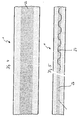
- FIGS. 4 to 6 are - as already stated - various embodiments of insulating elements 1 shown.
- the FIGS. 4 and 5 show here a first embodiment in which in plan view, a central region 22 has increased binder content.
- This region 22 of increased binder content can also be arranged in side view in the middle region of the height of the insulating element 1 and comprise approximately a third of the total height of the insulating element 1.
- FIG. 5 is shown with a line 27, the meandering position of the primary web 9 in the secondary web 15, which is generated via the shuttle station 11 in conjunction with the conveyor belt 13 arranged at right angles to this in the pendulum direction.
- FIG. 6 A second embodiment of the inventively embodied insulating element 1 is in FIG. 6 shown.
- This embodiment of the insulating element 1 differs from the embodiment of the insulating element 1 according to FIG. 4 in that the region 22 of increased binder content has a lattice-like structure.
- the region 22 of increased binder content has two webs 28 running parallel to one another and spaced apart, which extend in the longitudinal direction of the insulating element 1.
- the webs 28 have substantially a matching width, which is formed uniformly over the length of the insulating element 1.
- leg 29 Between the webs 28 extend at right angles thereto at uniform intervals leg 29, which also have increased binder content. Between the legs 29 and the webs 28 thus a square area having areas are arranged with usual or slightly increased binder content. The binder content in these areas corresponds to the binder content in the areas on both sides of the area 22 with increased binder content.
Landscapes
- Engineering & Computer Science (AREA)
- Chemical & Material Sciences (AREA)
- Textile Engineering (AREA)
- Life Sciences & Earth Sciences (AREA)
- Chemical Kinetics & Catalysis (AREA)
- General Chemical & Material Sciences (AREA)
- Organic Chemistry (AREA)
- Inorganic Chemistry (AREA)
- General Life Sciences & Earth Sciences (AREA)
- Geochemistry & Mineralogy (AREA)
- Materials Engineering (AREA)
- Dispersion Chemistry (AREA)
- General Engineering & Computer Science (AREA)
- Mechanical Engineering (AREA)
- Manufacturing & Machinery (AREA)
- Nonwoven Fabrics (AREA)
- Inorganic Insulating Materials (AREA)
- Sealing Material Composition (AREA)
- Chemical Or Physical Treatment Of Fibers (AREA)
Claims (33)
- Procédé de fabrication d'un élément en matériau isolant, en particulier d'un lé de matériau isolant qui peut être roulé et enroulé en fibres minérales, de préférence en laine minérale, pour lequel des fibres minérales sont déposées sur un dispositif de transport en ajoutant des liants et le fiant est ensuite durci, le taux de liant des fibres minérales étant varié après le dépôt sur le dispositif de transport de telle manière que des zones qui présentent un taux accru de liant sont configurées sur la largeur de l'élément en matériau isolant,
caractérisé en ce
que, pour configurer la zone de taux accru de liant, le liant est appliqué dans cette zone directement sur un intissé primaire, en particulier est pulvérisé sur cette zone,
que l'intissé primaire est comprimé en surface ou en forme de bandes dans la zone de l'apport de liant,
que du liant supplémentaire est appliqué sur les zones comprimées de l'intissé primaire et
que la zone de taux accru de liant qui s'étend dans le sens longitudinal de l'intissé primaire et qui est placée au milieu par rapport à la largeur de l'intissé primaire est comprimée de telle manière que la masse volumique apparente dans cette zone est accrue par rapport aux autres zones, l'élément en matériau isolant étant divisé sur sa largeur en zones de propriétés différentes. - Procédé selon la revendication 1,
caractérisé en ce
qu'un taux accru de liant entre 1,5 et 5,0% en masse, en particulier 2,0 à 2,5% en masse, est ajouté aux fibres minérales. - Procédé selon la revendication 1,
caractérisé en ce
qu'une résine synthétique duroplastique, déformable viscoplastique en minces pellicules ou à cassure ductile, comme par exemple un mélange de résine urée-phénol-formaldéhyde, de la résine de mélamine et/ou du polyester, est appliquée comme liant dans les zones de taux accru de liant. - Procédé selon la revendication 1,
caractérisé en ce
que les fibres minérales en dehors des zones de taux accru de liant sont pourvues d'un taux de liant de 2% en masse maximum de liant, en particulier entre 0,8 et 1,5% en masse de liant. - Procédé selon la revendication 4,
caractérisé en ce
qu'une masse volumique apparente entre 28 et 40 kg/cm3 est produite dans la zone de taux accru de liant et une masse volumique apparente entre 20 et 32 kg/m3 est produite dans les autres zones, en particulier voisines. - Procédé selon la revendication 1,
caractérisé en ce
que des liants anorganiques comme des nanocomposites et/ou en particulier des liants à rupture fragile avec des temps de durcissement courts, comme de l'huile siliceuse, du silicate de soude, du liant au phosphate et/ou une combinaison ou des mélanges de ceux-ci avec ou sans additions de matières synthétiques, sont chargés comme liants dans les zones à taux de liant accru. - Procédé selon la revendication 6,
caractérisé en ce
que jusqu'à 15% en masse, en particulier entre 5 et 10% en masse de liant anorganique, sont chargés dans les zones de taux accru de liant. - Procédé selon la revendication 7,
caractérisé en ce
que l'épaisseur de la couche avec un taux accru de liant est réduite en ajoutant une quantité plus importante de liant dans la zone de taux accru de liant. - Procédé selon la revendication 1,
caractérisé en ce
que des liants déformables plastiquement comme de l'acétate de polyvinyle, de la résine acrylique et/ou de la résine de silicone et/ou des mélanges de ceux-ci sont chargés dans les zones en dehors des zones à taux accru de liant. - Procédé selon la revendication 1,
caractérisé en ce
que les différents taux de liant sont commandés par des tuyères périphériques intérieures centrales et/ou périphériques extérieures dans la zone d'un appareil désintégrateur. - Procédé selon la revendication 10,
caractérisé en ce
que des liants différents sont amenés par les tuyères, de préférence en différentes quantités. - Procédé selon la revendication 11,
caractérisé en ce
que des nanocomposites sont ajoutés par la tuyère centrale et des liants duroplastiques et/ou thermoplastiques sont amenés par les tuyères périphériques. - Procédé selon la revendication 1, caractérisé en ce que le liant est appliqué après un poste d'oscillation sur l'intissé primaire.
- Procédé selon la revendication1,
caractérisé en ce
que des substances qui humidifient, comme des alcools et/ou des tensides, sont ajoutés au liant à appliquer. - Procédé selon la revendication 1 à 14,
caractérisé en ce
que le liant se durcit sous pression. - Procédé selon les revendications 1 à 15,
caractérisé en ce
que l'intissé primaire est comprimé avant et/ou après application du liant et/ou après le dépôt comme intissé secondaire. - Procédé selon la revendication 1,
caractérisé en ce
que le liant est appliqué en forme de bandes sur au moins une surface de l'intissé primaire dans le sens du transport. - Procédé selon la revendication 1,
caractérisé en ce
que le liant est appliqué en forme de bandes sur au moins une surface de l'intissé primaire transversalement par rapport au sens du transport. - Procédé selon la revendication 1,
caractérisé en ce
que le taux de liant est augmenté par l'apport de fibres imprégnées de liants, en particulier de fibres textiles, de verre, de synthèse et/ou de fibres naturelles ainsi que de fibres recyclées, qui sont dispersées de préférence par sections sur un intissé primaire. - Procédé selon la revendication 19,
caractérisé en ce
que les fibres imprégnées de liants sont appliquées en couches pendant la collecte des fibres minérales sur le dispositif de transport. - Procédé selon la revendication 19,
caractérisé en ce
que jusqu'à 25% en masse de fibres imprégnées de liants par rapport à la masse totale du lé de matériau isolant sont chargés. - Procédé selon la revendication 1,
caractérisé en ce
que des fibres minérales non imperméabilisées sont vaporisées pendant l'imprégnation avec des liants, de préférence après le durcissement des liants. - Procédé selon la revendication 22,
caractérisé en ce
que la vaporisation est effectuée avec des huiles minérales aliphatiques, des huiles végétales et/ou d'autres imperméabilisants qui se répartissent en rampant sur les surfaces des fibres minérales. - Elément en matériau isolant en fibres minérales liées à des liants, en particulier en fibres en laine minérale, de préférence en un lé de matériau isolant en fibres minérales, enroulable, à séparer en panneaux séparés, fabriqué selon le procédé selon les revendications 1 à 23, constitué par un corps limité en particulier en surface droite avec deux grandes surfaces placées parallèlement l'une à l'autre et espacées ainsi qu'en particulier avec des surfaces latérales et des surfaces frontales à angle droit par rapport aux grandes surfaces, qui sont placées également à angle droit et espacées l'une de l'autre et qui sont orientées parallèlement, au moins deux zones avec des fibres minérales étant placées sur la largeur de l'élément en matériau isolant dont au moins une zone (22) est configurée avec un taux accru de liant,
caractérisé en ce
que la zone de taux accru de liant est comprimée de telle manière que la masse volumique apparente dans cette zone (22) est accrue par rapport à d'autres zones, l'élément en matériau isolant étant séparé sur sa hauteur et/ou largeur en zones de propriétés différentes et que la zone (22) de taux accru de liant s'étend dans le sens longitudinal et est placée au milieu du lé de fibres minérales (1) par rapport à la largeur du lé de fibres minérales (1), cependant que le liant dans la zone (22) est configuré comme une résine synthétique duroplastique, déformable viscoplastique en minces pellicules ou à cassure ductile, comme par exemple un mélange de résine urée-phénol-formaldéhyde, de la résine de mélamine et/ou du polyester. - Elément en matériau isolant selon la revendication 24,
caractérisé en ce
que la masse volumique apparente dans la zone (22) est située entre 28 et 40 kg/m3 et entre 20 et 32 kg/m3 dans les autres zones, la masse volumique apparente dans la zone (22) étant plus élevée que dans les autres zones. - Elément en matériau isolant selon la revendication 24,
caractérisé en ce
que la zone (22) du taux accru de liant présente une hauteur et/ou une largeur d'environ 50 à 75%, en particulier de 66% de la largeur totale du lé de fibres minérales (1). - Elément en matériau isolant selon la revendication 24,
caractérisé en ce
que la zone (22) de taux accru de liant est configurée en forme de bandes. - Elément en matériau isolant selon la revendication 24,
caractérisé en ce
que la zone (22) de taux accru de liant est configurée de type réseau de quadrillage. - Elément en matériau isolant selon la revendication 24,
caractérisé en ce
que la zone (22) de taux accru de liant présente une largeur substantiellement constante sur toute la longueur du lé de fibres minérales (1). - Elément en matériau isolant selon la revendication 24,
caractérisé en ce
que la zone (22) de taux accru de liant est comprimée. - Elément en matériau isolant selon la revendication 24,
caractérisé en ce
que le liant est configuré dans la zone (22) comme un liant anorganique, par exemple un nanocomposite et/ou en particulier un liant à rupture fragile avec des temps de durcissement courts, comme de l'huile siliceuse, du silicate de soude, du liant au phosphate et/ou des combinaisons ou des mélanges de ceux-ci avec ou sans additions de matières synthétiques. - Elément en matériau isolant selon la revendication 24,
caractérisé en ce
que le liant en dehors de la zone (22) de taux accru de liant est configuré comme un liant déformable plastiquement comme de l'acétate de polyvinyle, de la résine acrylique et/ou de la résine de silicone et/ou des mélanges de ceux-ci. - Elément en matériau isolant selon la revendication 24,
caractérisé en ce que la zone (22) entre les grandes surfaces est configurée avec un taux accru de liant allant jusqu'à 15% en masse, de préférence entre 2 et 10% en masse, en particulier entre 2 et 2,5% en masse.
Applications Claiming Priority (2)
| Application Number | Priority Date | Filing Date | Title |
|---|---|---|---|
| DE10041481 | 2000-08-24 | ||
| DE10041481A DE10041481B4 (de) | 2000-08-24 | 2000-08-24 | Dämmstoffelement sowie Verfahren und Vorrichtung zur Herstellung eines Dämmstoffelementes, insbesondere einer roll- und/oder wickelbaren Dämmstoffbahn aus Mineralfasern |
Publications (3)
| Publication Number | Publication Date |
|---|---|
| EP1182177A1 EP1182177A1 (fr) | 2002-02-27 |
| EP1182177B1 EP1182177B1 (fr) | 2008-10-15 |
| EP1182177B2 true EP1182177B2 (fr) | 2015-04-01 |
Family
ID=7653578
Family Applications (1)
| Application Number | Title | Priority Date | Filing Date |
|---|---|---|---|
| EP01117083.4A Expired - Lifetime EP1182177B2 (fr) | 2000-08-24 | 2001-07-13 | Elément d'isolation , Procédé et installation pour la fabrication de matériaux isolants ainsi que nappe d'enveloppe en fibres minérales |
Country Status (3)
| Country | Link |
|---|---|
| EP (1) | EP1182177B2 (fr) |
| AT (1) | ATE411261T1 (fr) |
| DE (2) | DE10041481B4 (fr) |
Families Citing this family (15)
| Publication number | Priority date | Publication date | Assignee | Title |
|---|---|---|---|---|
| FR2839966B1 (fr) * | 2002-05-27 | 2004-07-23 | Saint Gobain Isover | Media filtrant comprenant des fibres minerales obtenues par centrifugation |
| AT414035B (de) * | 2003-01-24 | 2006-08-15 | Jenbacher Ag | Dämmeinrichtung zum zumindest teilweisen umfassen eines leitungssystems |
| EP1522642A1 (fr) * | 2003-10-06 | 2005-04-13 | Saint-Gobain Isover G+H Ag | Nappe de matière isolante en feutre de fibres minérales enroulée sur un rouleau destiné à être bloqué entre poutres |
| WO2005035459A1 (fr) | 2003-10-06 | 2005-04-21 | Saint-Gobain Isover | Porte coupe-feu et element rapporte de protection contre le feu pour ladite porte |
| DK1680561T3 (da) | 2003-10-06 | 2013-01-14 | Saint Gobain Isover | Isolationselement af mineralfibre til skibsbygning |
| JP4681558B2 (ja) * | 2003-10-06 | 2011-05-11 | サン−ゴバン・イソベール | 梁などの間の締付け状アセンブリ用の鉱物繊維フェルト製絶縁材料要素 |
| DE10349170A1 (de) | 2003-10-22 | 2005-05-19 | Saint-Gobain Isover G+H Ag | Dampfbremse mit einer Abschirmung gegen elektromagnetische Felder |
| FI121784B (sv) * | 2004-12-31 | 2011-04-15 | Paroc Oy Ab | Arrangemang och förfarande vid framställning av mineralull samt fibreringsanordning |
| FI120388B (sv) * | 2004-12-31 | 2009-10-15 | Paroc Oy Ab | Förfarande och anordning vid framställning av mineralfibrer samt fibreringshjularrangemang |
| FR2928146B1 (fr) † | 2008-02-28 | 2010-02-19 | Saint Gobain Isover | Produit a base de fibres minerales et son procede d'obtention. |
| IT1393341B1 (it) * | 2009-03-11 | 2012-04-20 | Warmor Roofing Srl | Metodo per la realizzazione di un pannello, in particolare per l'isolamento termoacustico, pannello realizzato con detto metodo e impianto per la realizzazione di detto pannello |
| DE102009035104B4 (de) * | 2009-07-29 | 2020-06-25 | Saint-Gobain Isover G+H Ag | Dämmstoffbahn aus Mineralwolle sowie Großgebinde aus derartigen zu Rollen gewickelten Dämmstoffbahnen |
| KR101856923B1 (ko) * | 2018-02-08 | 2018-05-10 | 박진성 | 폭 조절이 가능한 부직포 제조장치 |
| CN110923951A (zh) * | 2019-12-24 | 2020-03-27 | 陈凯 | 一种防火密度板生产用混合喷胶装置 |
| WO2021140295A1 (fr) * | 2020-01-09 | 2021-07-15 | Saint-Gobain Isover | Procédé de fabrication de produits d'isolation à base de laine minérale |
Citations (7)
| Publication number | Priority date | Publication date | Assignee | Title |
|---|---|---|---|---|
| DE3612857A1 (de) † | 1986-04-16 | 1986-09-18 | Grünzweig + Hartmann und Glasfaser AG, 6700 Ludwigshafen | Zu einer rolle aufwickelbare daemmstoffbahn, insesondere aus mineralfaserfilz, sowie deren verwendung |
| EP0277500A2 (fr) † | 1987-01-21 | 1988-08-10 | Deutsche Rockwool Mineralwoll-GmbH | Procédé pour la fabrication en continu d'une feuille de matériau fibreux isolant, et appareil pour exécuter ce procédé |
| EP0375486A1 (fr) † | 1988-12-21 | 1990-06-27 | Isover Saint-Gobain | Procédé d'obtention d'un panneau surface à base de fibres minérales |
| DE3940896A1 (de) † | 1988-12-16 | 1990-06-28 | Rockwool Ab | Verfahren zum einbringen von klebstoffen in schlackenwolle |
| DE19608647C1 (de) † | 1996-03-06 | 1997-10-23 | Jens Bretthauer | Verfahren zum Herstellen von Vliesen |
| WO1998021266A1 (fr) † | 1996-11-15 | 1998-05-22 | Institut Für Neue Materialien Gem. Gmbh | Materiaux composites |
| WO1998028501A1 (fr) † | 1996-12-23 | 1998-07-02 | Isover Saint-Gobain | Element d'isolation destine a etre installe par serrage entre des chevrons de toits ou des poutres d'autres constructions en bois |
Family Cites Families (8)
| Publication number | Priority date | Publication date | Assignee | Title |
|---|---|---|---|---|
| SE463817B (sv) * | 1988-12-16 | 1991-01-28 | Rockwool Ab | Saett och anordning att tillsaetta bindemedel till nybildade mineralullsfibrer |
| FR2668470B1 (fr) * | 1990-10-29 | 1992-12-24 | Saint Gobain Isover | Procede et dispositif de production de fibres par centrifugation interne et application au fibrage de certains verres. |
| DK165926B (da) * | 1990-12-07 | 1993-02-08 | Rockwool Int | Fremgangsmaade til fremstilling af isoleringsplader sammensat af indbyrdes forbundne stavformede mineralfiberelementer |
| CZ290109B6 (cs) * | 1991-08-02 | 2002-06-12 | Isover Saint-Gobain | Způsob výroby minerální vlny z roztaveného minerálního materiálu a zařízení pro provádění tohoto způsobu |
| AU5311698A (en) * | 1996-12-23 | 1998-07-17 | Rockwool International A/S | A method of producing a mineral fiber web, a plant for producing a mineral fiberweb, and a mineral fiber-insulating plate |
| DE19808518C1 (de) * | 1998-02-27 | 1999-08-05 | Rockwool Mineralwolle | Verfahren und Vorrichtung zur Beschichtung und/oder Imprägnierung von Mineralwolleprodukten |
| DE69901611T3 (de) * | 1998-04-06 | 2012-02-23 | Rockwool International A/S | Synthetische glasfasermatten und deren herstellung |
| DE69904476T2 (de) * | 1998-05-18 | 2003-09-11 | Rockwool International A/S, Hedehusene | Stabilisierte, wässerige phenolharz-bindemittel für mineralwolle und verfahren zur herstellung von mineralwollprodukten |
-
2000
- 2000-08-24 DE DE10041481A patent/DE10041481B4/de not_active Revoked
-
2001
- 2001-07-13 AT AT01117083T patent/ATE411261T1/de active
- 2001-07-13 EP EP01117083.4A patent/EP1182177B2/fr not_active Expired - Lifetime
- 2001-07-13 DE DE50114414T patent/DE50114414D1/de not_active Expired - Lifetime
Patent Citations (7)
| Publication number | Priority date | Publication date | Assignee | Title |
|---|---|---|---|---|
| DE3612857A1 (de) † | 1986-04-16 | 1986-09-18 | Grünzweig + Hartmann und Glasfaser AG, 6700 Ludwigshafen | Zu einer rolle aufwickelbare daemmstoffbahn, insesondere aus mineralfaserfilz, sowie deren verwendung |
| EP0277500A2 (fr) † | 1987-01-21 | 1988-08-10 | Deutsche Rockwool Mineralwoll-GmbH | Procédé pour la fabrication en continu d'une feuille de matériau fibreux isolant, et appareil pour exécuter ce procédé |
| DE3940896A1 (de) † | 1988-12-16 | 1990-06-28 | Rockwool Ab | Verfahren zum einbringen von klebstoffen in schlackenwolle |
| EP0375486A1 (fr) † | 1988-12-21 | 1990-06-27 | Isover Saint-Gobain | Procédé d'obtention d'un panneau surface à base de fibres minérales |
| DE19608647C1 (de) † | 1996-03-06 | 1997-10-23 | Jens Bretthauer | Verfahren zum Herstellen von Vliesen |
| WO1998021266A1 (fr) † | 1996-11-15 | 1998-05-22 | Institut Für Neue Materialien Gem. Gmbh | Materiaux composites |
| WO1998028501A1 (fr) † | 1996-12-23 | 1998-07-02 | Isover Saint-Gobain | Element d'isolation destine a etre installe par serrage entre des chevrons de toits ou des poutres d'autres constructions en bois |
Also Published As
| Publication number | Publication date |
|---|---|
| DE50114414D1 (de) | 2008-11-27 |
| DE10041481B4 (de) | 2006-01-19 |
| DE10041481A1 (de) | 2002-03-21 |
| EP1182177A1 (fr) | 2002-02-27 |
| ATE411261T1 (de) | 2008-10-15 |
| EP1182177B1 (fr) | 2008-10-15 |
Similar Documents
| Publication | Publication Date | Title |
|---|---|---|
| EP1182177B2 (fr) | Elément d'isolation , Procédé et installation pour la fabrication de matériaux isolants ainsi que nappe d'enveloppe en fibres minérales | |
| EP0277500B1 (fr) | Procédé pour la fabrication en continu d'une feuille de matériau fibreux isolant, et appareil pour exécuter ce procédé | |
| DE69909454T2 (de) | Verfahren und vorrichtung zur herstellung eines mineralfaserprodukts. | |
| DE60034782T2 (de) | Mineralfaserdämmplatte mit einer steifen aussenschicht, ein herstellungsverfahren und verwendung des wärmedämmprodukts für dach- und fassadenbekleidung | |
| EP0578107B1 (fr) | Non-tissé en fibres naturelles et l'application de celui ci | |
| DE102004062649B4 (de) | Verfahren zur Herstellung einer Holzfaserdämmstoffplatte bzw.-matte und nach diesem Verfahren hergestellte Holzfaserdämmstoffplatten bzw.-matten | |
| EP1522642A1 (fr) | Nappe de matière isolante en feutre de fibres minérales enroulée sur un rouleau destiné à être bloqué entre poutres | |
| DE19810862C2 (de) | Dämmplatte aus Stroh und Verfahren zur Herstellung | |
| EP1674633B1 (fr) | Plaque en fibres de bois isolant ou matte | |
| DE4409416C2 (de) | Mineralwolle-Dämmplatte, ihre Verwendungen und Verfahren zu ihrer Herstellung | |
| EP0821746A1 (fr) | Element thermo-isolant en fibres vegetales | |
| EP1708876B1 (fr) | Procede de fabrication d'une bande de materiau isolant a partir de fibres minerales et bande de materiau isolant ainsi obtenue | |
| DE19919004A1 (de) | Verfahren und Vorrichtung zur Herstellung von Dämmstoffen aus Mineralfasern sowie Dämmstoffelement aus Mineralfasern | |
| EP1559845B1 (fr) | Procédé de fabrication d' une nappe isolante en fibres minérales et nappe isolante | |
| EP1561847B1 (fr) | Procédé et dispositif pour la fabrication de matériaux isolants en feuilles ou plaques à base de fibres minérales | |
| EP1335080B1 (fr) | Panneau isolant pour isolation acoustique et/ou thermique, et couche d'isolation | |
| DE10146765B4 (de) | Verfahren zur Herstellung einer Verpackungs- oder Transporteinheit für plattenförmige Dämmstoffe aus Mineralfasern, Verpackungs- oder Transporteinheit sowie Dämmstoffplatte | |
| EP1893825B1 (fr) | Procede et dispositif pour realiser des elements en materiau isolant en fibres minerales | |
| DE102024130444B3 (de) | Verfahren zur Herstellung einer luftgelegten Faserstoffbahn | |
| DE102006028841B4 (de) | Dämmanordnung und Verfahren zur Herstellung eines Dämmstoffstreifens | |
| EP1390262B1 (fr) | Procede de realisation d'une unite d'emballage et/ou de transport pour materiaux isolants en forme de plaques constitues de fibres minerales, unite d'emballage et/ou de transport, et plaque de materiau isolant | |
| EP0512479B1 (fr) | Panneau et procédé pour sa fabrication | |
| DE102024130446B3 (de) | Verfahren und Maschine zur Herstellung einer luftgelegten Faserstoffbahn | |
| EP1106743A2 (fr) | Procédé et dispositif de fabrication d'une bande d'isolation fibreuse | |
| EP2369078B1 (fr) | Matériau d'isolation |
Legal Events
| Date | Code | Title | Description |
|---|---|---|---|
| PUAI | Public reference made under article 153(3) epc to a published international application that has entered the european phase |
Free format text: ORIGINAL CODE: 0009012 |
|
| AK | Designated contracting states |
Kind code of ref document: A1 Designated state(s): AT BE CH CY DE DK ES FI FR GB GR IE IT LI LU MC NL PT SE TR Kind code of ref document: A1 Designated state(s): AT DE |
|
| AX | Request for extension of the european patent |
Free format text: AL;LT;LV;MK;RO;SI |
|
| 17P | Request for examination filed |
Effective date: 20020327 |
|
| AKX | Designation fees paid |
Free format text: AT DE |
|
| 17Q | First examination report despatched |
Effective date: 20040419 |
|
| 17Q | First examination report despatched |
Effective date: 20040419 |
|
| GRAP | Despatch of communication of intention to grant a patent |
Free format text: ORIGINAL CODE: EPIDOSNIGR1 |
|
| GRAS | Grant fee paid |
Free format text: ORIGINAL CODE: EPIDOSNIGR3 |
|
| GRAA | (expected) grant |
Free format text: ORIGINAL CODE: 0009210 |
|
| AK | Designated contracting states |
Kind code of ref document: B1 Designated state(s): AT DE |
|
| REF | Corresponds to: |
Ref document number: 50114414 Country of ref document: DE Date of ref document: 20081127 Kind code of ref document: P |
|
| PLBI | Opposition filed |
Free format text: ORIGINAL CODE: 0009260 |
|
| PLAX | Notice of opposition and request to file observation + time limit sent |
Free format text: ORIGINAL CODE: EPIDOSNOBS2 |
|
| 26 | Opposition filed |
Opponent name: SAINT-GOBAIN ISOVER G+H AG Effective date: 20090714 |
|
| PLAB | Opposition data, opponent's data or that of the opponent's representative modified |
Free format text: ORIGINAL CODE: 0009299OPPO |
|
| PLBB | Reply of patent proprietor to notice(s) of opposition received |
Free format text: ORIGINAL CODE: EPIDOSNOBS3 |
|
| PLAB | Opposition data, opponent's data or that of the opponent's representative modified |
Free format text: ORIGINAL CODE: 0009299OPPO |
|
| R26 | Opposition filed (corrected) |
Opponent name: SAINT-GOBAIN ISOVER G+H AG Effective date: 20090714 |
|
| APBM | Appeal reference recorded |
Free format text: ORIGINAL CODE: EPIDOSNREFNO |
|
| APBP | Date of receipt of notice of appeal recorded |
Free format text: ORIGINAL CODE: EPIDOSNNOA2O |
|
| APAH | Appeal reference modified |
Free format text: ORIGINAL CODE: EPIDOSCREFNO |
|
| APBU | Appeal procedure closed |
Free format text: ORIGINAL CODE: EPIDOSNNOA9O |
|
| APAN | Information on closure of appeal procedure modified |
Free format text: ORIGINAL CODE: EPIDOSCNOA9O |
|
| PUAH | Patent maintained in amended form |
Free format text: ORIGINAL CODE: 0009272 |
|
| STAA | Information on the status of an ep patent application or granted ep patent |
Free format text: STATUS: PATENT MAINTAINED AS AMENDED |
|
| 27A | Patent maintained in amended form |
Effective date: 20150401 |
|
| AK | Designated contracting states |
Kind code of ref document: B2 Designated state(s): AT DE |
|
| REG | Reference to a national code |
Ref country code: DE Ref legal event code: R102 Ref document number: 50114414 Country of ref document: DE |
|
| REG | Reference to a national code |
Ref country code: DE Ref legal event code: R102 Ref document number: 50114414 Country of ref document: DE Effective date: 20150401 |
|
| PGFP | Annual fee paid to national office [announced via postgrant information from national office to epo] |
Ref country code: DE Payment date: 20150707 Year of fee payment: 15 |
|
| PGFP | Annual fee paid to national office [announced via postgrant information from national office to epo] |
Ref country code: AT Payment date: 20150625 Year of fee payment: 15 |
|
| REG | Reference to a national code |
Ref country code: DE Ref legal event code: R119 Ref document number: 50114414 Country of ref document: DE |
|
| REG | Reference to a national code |
Ref country code: AT Ref legal event code: MM01 Ref document number: 411261 Country of ref document: AT Kind code of ref document: T Effective date: 20160713 |
|
| PG25 | Lapsed in a contracting state [announced via postgrant information from national office to epo] |
Ref country code: DE Free format text: LAPSE BECAUSE OF NON-PAYMENT OF DUE FEES Effective date: 20170201 |
|
| PG25 | Lapsed in a contracting state [announced via postgrant information from national office to epo] |
Ref country code: AT Free format text: LAPSE BECAUSE OF NON-PAYMENT OF DUE FEES Effective date: 20160713 |