EP1184104A1 - Insert pour masselotte - Google Patents
Insert pour masselotte Download PDFInfo
- Publication number
- EP1184104A1 EP1184104A1 EP01117412A EP01117412A EP1184104A1 EP 1184104 A1 EP1184104 A1 EP 1184104A1 EP 01117412 A EP01117412 A EP 01117412A EP 01117412 A EP01117412 A EP 01117412A EP 1184104 A1 EP1184104 A1 EP 1184104A1
- Authority
- EP
- European Patent Office
- Prior art keywords
- feeder
- feeder insert
- molding
- elements
- shaped element
- Prior art date
- Legal status (The legal status is an assumption and is not a legal conclusion. Google has not performed a legal analysis and makes no representation as to the accuracy of the status listed.)
- Granted
Links
- 238000005266 casting Methods 0.000 claims abstract 4
- 229910001338 liquidmetal Inorganic materials 0.000 claims abstract 3
- 238000000034 method Methods 0.000 claims abstract 3
- 238000004519 manufacturing process Methods 0.000 claims abstract 2
- 238000000465 moulding Methods 0.000 claims 7
- 239000012778 molding material Substances 0.000 claims 2
- 238000005058 metal casting Methods 0.000 claims 1
- 239000003110 molding sand Substances 0.000 claims 1
- 239000011796 hollow space material Substances 0.000 abstract 1
- 239000002184 metal Substances 0.000 abstract 1
- 229910052751 metal Inorganic materials 0.000 abstract 1
- 150000002739 metals Chemical class 0.000 abstract 1
Images

Classifications
-
- B—PERFORMING OPERATIONS; TRANSPORTING
- B22—CASTING; POWDER METALLURGY
- B22C—FOUNDRY MOULDING
- B22C9/00—Moulds or cores; Moulding processes
- B22C9/08—Features with respect to supply of molten metal, e.g. ingates, circular gates, skim gates
- B22C9/088—Feeder heads
Definitions
- the present invention relates primarily to a closed one Feeder insert, also called feeder for short, for use with Pouring metals into molds, with a cavity for receiving liquid Metal.
- Such feeder inserts are used in the manufacture of a mold integrated into this and form a space surrounded by molding material, the has a passage (passage) to the mold cavity and during casting is filled by the pouring stream with liquid metal that during the Flow solidification process back to the casting and the volume deficit to compensate for the solidification of the casting. In this way the Formation of so-called blowholes (these are shrinkage cavities caused by the Metal volume contraction during the solidification process) prevented.
- the metal in the feeder solidifies later than the metal of the casting, i.e. the module (ratio of volume to surface) of the feeder must be larger than that of the casting.
- the modules (ratio of volume to surface) of the feeder must be larger than that of the casting.
- the walls of the feeder become frequent made of an exothermic material, for example an aluminothermic Mixture, formed.
- an exothermic material for example an aluminothermic Mixture
- the molding material usually molding sand, in individual cases also other granular materials
- Feeder inserts are often designed to be very small.
- the feeder insert tapers thus considerably towards its top surface, and at Applying the molding material to the molding plate often gives rise to the subsequent problem on that the compression of the molding material in the vicinity of the esophagus insufficiently close to the top surface, which is disadvantageous when casting is.
- Spring mandrels as well as fixed (rigid) mandrels are designed to to hold a feeder insert in a predetermined position.
- she typically include (a) a tubular member for attachment a model plate, (b) one arranged in the tubular element Spring and (c) a resting on the spring, in the longitudinal direction within the tubular element telescopically displaceable mandrel tip element.
- Such a spring mandrel is usually on the model plate (model surface) attached, and then a feeder insert is placed on it, the lower surface of which is in the starting arrangement before the filling of the Molding material is located at a predetermined distance from the model surface.
- the subsequent filling of the molding material therefore also runs between model surface and feeder (bottom surface).
- the feeder insert placed on the spring mandrel acts a force in the direction of the model plate that causes the feeder insert against the action of the spring force in the direction of the Model plate is pressed. The in the gap between feeder insert and The molded material layer on the model plate is compressed.
- the footprint of the feeder insert to be specified should be included preferably be dimensioned small without relevant stability disadvantages can.
- the feeder insert to be specified should also be together can be used with a crushing core that separates the residual feeder relieved by the casting.
- a crushing core is in the Framework of the present text as part of the use of food understood and not as a separate component.
- the task is solved by specifying a closed one Feeder insert of the type mentioned, wherein the feeder insert at least two into one another along a longitudinal axis of the feeder (telescopic) comprises displaceable shaped elements which liquid the cavity for receiving Enclose metal on the side.
- a first shaped element is closer to Passage of the feeder insert arranged as an associated second Feature.
- the displaceability of the first and second shaped elements into one another causes that during a normal compression process in the longitudinal direction of the feeder high acting on the feeder insert according to the invention Compression pressures (compression forces) do not lead to its destruction, but only to a tolerated, by the compressibility of the surrounding molding material (molding sand) limited insertion of a molding element into the other.
- Compression pressures compression forces
- the footprint of the feeder insert can small and the wall of the feeder is comparatively thin.
- the shaped elements should be out of their initial arrangement, i.e. out the relative arrangement out for the molded elements before wrapping the Feeder insert with molding material is provided, at least by 5 mm, can preferably be pushed into each other by 10 mm.
- the feeder insert can meet the requirements of the individual case correspondingly, for example, in the manner of a compact or ball feeder designed or with an almost cylindrical feeder cap in the upper area be provided.
- spring mandrels with the feeder inserts according to the invention is therefore not excluded, but usually can on it to be dispensed with.
- a preferred feeder insert according to the invention is therefore set up for use with a centering mandrel, in particular can be designed as a self-centering feeder.
- a self-centering Suer has one or more wall sections that towards the upper one in operation (opposite the feeder passage) Taper the end wall of the feeder so that a thorn tip when positioning the feeder insert in these along these sections Target position is performed.
- Is a self-centering feeder according to the invention especially suitable for use on fast molding lines.
- First and second shaped element of a feeder insert according to the invention can be glued together or otherwise after their manufacture get connected.
- the shaped elements can also be used as separate parts stored and combined (stacked) as needed.
- Identical first (or second) form elements can also be constructed (e.g. in size) different second (or first) form elements can be combined into respective feeder inserts according to the invention.
- the holding elements are preferably an integral part of the respective formula element, and they can be used in the manufacture of each Form elements can be molded onto this without an additional step. It can with them in particular around standing or clamping projections, rotating Stand rings, pins that can be brought into engagement with complementary recesses or act like that. It is important that the holding elements are designed to operate in the foundry when the first and second
- the molding element is still roughly in its initial arrangement, the molding material but is already filled in the mold box by the subsequent one Molding material compression process from its associated shaped element can be separated or at least deformed to the extent that the first and can slide one another into each other.
- the holding elements are therefore preferably only via small connecting surfaces with their associated one Form element connected.
- a Spring mandrel As an alternative to using holding elements, the use of a Spring mandrel.
- One such can namely be a second one, the upper one in operation Form element in the intended starting position relative to the model surface and hold to the first shaped element without the inventive Feeder insert itself includes holding elements. Since spring mandrels, however, like mentioned at the outset are quite expensive and prone to wear, their use be limited to exceptional cases.
- This is preferably closer to the passage of the feeder insert this forming the first shaped element so that it (if necessary after separating or deforming holding elements) into the second shaped element can be inserted.
- the outer dimensions of the first, in Operation of lower form elements closer to the casting are therefore preferred smaller than the internal dimensions of the associated second, upper in operation Form element.
- This configuration is the reverse of that (Also according to the invention) embodiment in which the upper in operation Shaped element can be inserted into the lower shaped element, advantageous because it ensures that no disturbing quantities are present during the filling process Penetrate molding material into the first molding element.
- An embodiment is particularly advantageous in which the first, in Operation lower mold element is designed so that it (telescopic) in the second shaped element can be inserted, the outer wall of the first form elements in the inner wall of the second form element intervenes.
- the gap width between the outer wall of the first Form elements and the inner wall of the second form element is in the intended starting arrangement of the shaped elements, which if necessary is characterized by the position of the holding elements, preferably maximum 3 mm, advantageously not more than 1.5 mm.
- the shaped elements should come from their intended, if necessary output arrangement defined by the holding elements in the longitudinal direction of the feeder by at least 5 mm, preferably by at least 10 mm leave before pushing due to further nesting Forces occurring between the shaped elements to tear or Breaking of the first or second feature comes.
- the first and / or the second shaped element comprises one or more guide elements which are set up tilting or tilting of the two shaped elements relative to one another to prevent at least essentially when this (from the output arrangement out) shifted into each other along the longitudinal axis of the feeder become.
- These guide elements preferably have the shape themselves Thin strips or ridges extending along the length of the feeder, and them are advantageously located on the outer wall of that molded element, which can be inserted into the partner form element; in So in a lot of cases they are on the outside of the first Formula elements arranged.
- the first molded element is an inventive one Feeder insert integrated a breaking edge, which if necessary Is part of a crushing core, which is then directly on the model plate during operation can be put on.
- This integration of a breaking edge ensures a significant reduction in Cleaning effort in comparison with the known feeder inserts used for Use with spring mandrels are provided and therefore no breaking edge (no crusher core).
- the footprint of the feeder according to the invention can be very difficult, especially when using a crushing edge (a crushing core) be kept small.
- the feeder insert according to the invention or the associated shaped elements can partially or completely from insulating or exothermic molding compounds be made. If a crushing core is integrated in the first shaped element, so this is typically not exothermic, the associated second The shaped element will then often be exothermic.
- the feeder inserts according to the invention comprise two or more Form elements that can be combined as required when stored separately can.
- the invention therefore also relates to a kit for manufacturing of a feeder insert according to the invention, comprising a first shaped element and a second shaped element which can be arranged so that they can be moved into one another along a longitudinal axis of the feeder.
- preferred Embodiments of the form elements belonging to the kit are the above statements to remove the feeder insert according to the invention.
- the molding machine usually includes a model plate (i.e. a model device for molding machines, usually consisting of a flat plate with cast-in or mechanically fastened models), and the first mold element is preferably arranged so that it is in front the compression process in direct contact with the model plate (the Model surface). This is especially true if in the first Forming element is integrated into a crushing core.
- a model plate i.e. a model device for molding machines, usually consisting of a flat plate with cast-in or mechanically fastened models
- the first mold element is preferably arranged so that it is in front the compression process in direct contact with the model plate (the Model surface). This is especially true if in the first Forming element is integrated into a crushing core.
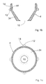
- Feeder insert 2 comprises a first (lower) molded element 4 and a second (Upper) shaped element 6, both shaped elements being essentially rotationally symmetrical are trained.
- the longitudinal axis of rotation the Spelser insert 2 is shown by a dashed line Line 20 marked.
- the first shaped element 4 is again separately in FIG. 1b Longitudinal section and shown in Fig. 1b in plan view. It's over a molding compound (e.g. insulating or exothermic) shaped and relative thin-walled.
- the footprint of the first form element 4, with the this sits on a model plate 22 is small, the footprint diameter is only about 40 mm, the diameter of the inside of the footprint lying feeder passage only about 20 mm.
- the first shaped element widens to the maximum outside Diameter of about 77 mm conical, and the conical so defined Section 34 then merges into an upper section 44, which follows very slightly conical up to a diameter of about 76 mm rejuvenated.
- Retaining projections 12 are formed.
- the (imaginary) connection surfaces between Retaining projections 12 and shaped element 4 are each quite small, so that the Holding projections 12 mechanically from the molded element with little effort can be separated.
- a total of four are also assigned to the holding projections 12 Guide and spacer strips 14, which start from the holding projections extend in the longitudinal direction of the feeder insert 2 and opposite the outer wall of the upper section 44 of the lower molding 4 each project by about 2 mm.
- the second (upper) molding element 6 is the second (upper) molding element 6. It is molded from an exothermic molding compound and is also quite thin-walled educated. The outer contour of the upper molded element 6 tapers upwards slightly towards one on the outside essentially flat upper wall termination 36.
- the inner wall of the upper Formula elements 4 initially proceed from its lower edge 26 parallel to the outer wall of the upper section 44 of the lower molding 4 and then goes into a conically tapering wall section 46 above, along which the tip of a centering mandrel at Positioning the feeder insert can be performed.
- the conical Wall section 46 finally opens into one in the feed axis lying, through the end 36 centering recess 56 for Picking up a mandrel tip.
- the two shaped elements 4, 6 are designed so that the four Guide strips 14 of the lower molding 4 frictionally on the inner wall of the upper molding element 6, if this, as in Fig. 1a shown in the starting arrangement on the four retaining projections of the lower form elements 4 rests. They therefore cause an interference fit and prevent an undesirable lateral displacement of the two shaped elements; they also define a uniform width of the gap between the lower (here inner) and upper (here outer) form element.
- a centering mandrel 16 is also shown in FIG. which is attached to the model plate 22 and from there (always in the feeder axis of rotation 20 lying) through the feeder passage 10 and through the feeder cavity into the centering recess 56 extends.
- the two shaped elements 4, 6 of the feeder insert 2 can be Slide telescopically into each other if parallel to the axis of rotation 20 a force directed onto the model plate 22 (arrow F) on the feeder insert acts, as for example after the filling of molding material Compression molding is the case (see Fig. 3a-d).
- the force just needs to do this be sufficiently large to hold the retaining projections 12 from the lower mold element 4 separate.
- the inner wall of the second (upper, outer) molded element approaches itself when pushed onto the first (lower, inner) form element Outer wall continuously and finally arrives after a displacement path of approx. 15 mm, all around in contact with it. Such a shift path sufficient for many compaction processes.
- the end position of the lower edge 26 of the upper molded element 6 after covering the above Displacement path is indicated by a dashed line.
- the Guide strips 14 are 4.6 when pushing the form elements deformed or separated and / or cut into the inner wall of the outer (upper) form elements 6.
- the centering recess 56 extends through the upper end wall of the feeder insert 2 and the tip of the centering mandrel includes a cylindrical section that is significantly longer than 15 mm and the diameter of which corresponds to the inner diameter of the centering recess 56 is adjusted. That is why it happens when telescoping the upper one on the lower form element does not cause disability; the thorn tip kicks rather, emerge unhindered from the feeder insert.
- the lower edge 26 of the wall projecting beyond the lower shaped element 4 of the upper molding element 6 acts like one during a compression process Stamp surface on the molding material to be compressed between edge 26 and Model plate 22.
- the (also) using a compression process The operations of the feeder insert 2 are described below with reference to FIG. 3a-d explained in more detail.
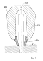
- FIG. 2 shows an alternative feeder insert 202 according to the invention shown in longitudinal section.
- the feeder insert 202 is more compact and thicker walled than the feeder insert 2.
- the existing one here Centering recess 256 does not pass through the upper feeder end, but extends so far in the longitudinal direction of the feeder insert that an assigned centering pin is inserted far enough into it can be, if the upper mold element 206 telescopically on the lower Form element 204 is moved in the direction of the model plate.
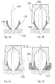
- 3a-d is an inventive method for arrangement of a feeder insert according to the invention in a casting mold schematically shown.
- the following explanations apply to the use of feeders 1a-c as well as for the feeder insert from FIG. 2.
- a first shaped element 104 is placed on a centering mandrel 116 placed, which is attached to a model plate 122.
- the form element 104 is in direct contact with the model plate 122 brought.
- a second shaped element 106 is then placed on the first shaped element 104 placed so that it is supported by this.
- To holding projections 112 are provided, for example, in their shape and function of the holding projections 12 explained with reference to FIGS. 1a-c correspond.
- a composite feeder insert 102 in its starting arrangement, cf. Fig. 1a.
- the feeder insert is used 102 coated with molding sand 150 or another molding material (wrapping only indicated in the lower area).
- the holding projections 112 are from the first Molded element 104 broken off, the second (upper) shaped element 106 telescopically a little bit onto the first (lower) shaped element 104 postponed.
- the displacement path D of the second molding element 106 on the the first shaped element 104 fixed in position is determined by the dimension predetermined and limited the compression of molding material.
Landscapes
- Engineering & Computer Science (AREA)
- Mechanical Engineering (AREA)
- Molds, Cores, And Manufacturing Methods Thereof (AREA)
- Moulds For Moulding Plastics Or The Like (AREA)
- Valve-Gear Or Valve Arrangements (AREA)
- Mechanical Treatment Of Semiconductor (AREA)
- Eye Examination Apparatus (AREA)
- Injection Moulding Of Plastics Or The Like (AREA)
Priority Applications (1)
| Application Number | Priority Date | Filing Date | Title |
|---|---|---|---|
| DE20122062U DE20122062U1 (de) | 2000-08-08 | 2001-07-19 | Speisereinsatz |
Applications Claiming Priority (2)
| Application Number | Priority Date | Filing Date | Title |
|---|---|---|---|
| DE10039519A DE10039519B4 (de) | 2000-08-08 | 2000-08-08 | Speisereinsatz |
| DE10039519 | 2000-08-08 |
Publications (2)
| Publication Number | Publication Date |
|---|---|
| EP1184104A1 true EP1184104A1 (fr) | 2002-03-06 |
| EP1184104B1 EP1184104B1 (fr) | 2004-12-01 |
Family
ID=7652277
Family Applications (1)
| Application Number | Title | Priority Date | Filing Date |
|---|---|---|---|
| EP01117412A Expired - Lifetime EP1184104B1 (fr) | 2000-08-08 | 2001-07-19 | Insert pour masselotte |
Country Status (4)
| Country | Link |
|---|---|
| EP (1) | EP1184104B1 (fr) |
| AT (1) | ATE283740T1 (fr) |
| DE (2) | DE10039519B4 (fr) |
| ES (1) | ES2232543T3 (fr) |
Cited By (28)
| Publication number | Priority date | Publication date | Assignee | Title |
|---|---|---|---|---|
| WO2005051568A1 (fr) * | 2003-10-28 | 2005-06-09 | Foseco International Limited | Element de masselotte pour fonderie de metaux |
| EP1728570A1 (fr) | 2005-06-04 | 2006-12-06 | GTP-Schäfer Giesstechnische Produkte GmbH | Masselotte avec un bas sous |
| EP1775045A2 (fr) | 2005-10-14 | 2007-04-18 | Hofmann Ceramic GmbH | Insert pour masselotte pour une moule de coulage |
| EP1920859A1 (fr) * | 2006-10-31 | 2008-05-14 | GTP-Schäfer Giesstechnische Produkte GmbH | Insert en deux parties pour masselotte avec un bas sous |
| EP1985392A1 (fr) * | 2007-04-18 | 2008-10-29 | GTP-Schäfer Giesstechnische Produkte GmbH | Insert d'alimenteur doté d'une zone de sol gainée |
| AU2007324542B2 (en) * | 2006-11-24 | 2011-06-02 | Chemex Gmbh | Feeder insert and feeder element |
| DE10059481B4 (de) * | 2000-11-30 | 2012-02-23 | AS Lüngen GmbH | Speiser mit einem rohrähnlichen Körper |
| DE202011103718U1 (de) | 2011-02-17 | 2012-07-31 | Foseco International Ltd. | Speiserelement |
| DE202012102546U1 (de) | 2012-04-30 | 2012-08-07 | Foseco International Ltd. | Einschnürspeiser (Neck-Down Feeder) |
| DE202012102418U1 (de) | 2012-05-15 | 2013-05-16 | Foseco International Ltd. | Speiserelement |
| WO2014083155A1 (fr) | 2012-11-29 | 2014-06-05 | Gtp Schäfer Giesstechnische Produkte Gmbh | Procédé de fabrication d'une masselotte comportant un corps de masselotte exothermique ainsi qu'une coque extérieure isolante |
| WO2014191423A1 (fr) * | 2013-05-27 | 2014-12-04 | Chemex Gmbh | Manchon de masselotte, élément de formage du manchon de masselotte et procédé de coulée de métal les utilisant |
| CN104994973A (zh) * | 2013-02-15 | 2015-10-21 | 凯美克斯有限责任公司 | 冒口插件和用于将其设置在铸模中的方法 |
| CN105364013A (zh) * | 2014-08-07 | 2016-03-02 | 胡坦斯·阿尔伯图斯化学厂有限公司 | 在制造能分开的铸模时应用的装置 |
| DE202016104786U1 (de) | 2015-09-02 | 2016-11-21 | Foseco International Ltd. | Speiserelement |
| DE202016104787U1 (de) | 2015-09-02 | 2016-11-28 | Foseco International Ltd. | Speisersystem |
| WO2017025702A1 (fr) * | 2015-09-02 | 2017-02-16 | Foseco International Limited | Système de masselotte |
| CN106660111A (zh) * | 2014-09-02 | 2017-05-10 | 福塞科国际有限公司 | 进料系统 |
| DE102016202795A1 (de) | 2016-02-23 | 2017-08-24 | HÜTTENES-ALBERTUS Chemische Werke Gesellschaft mit beschränkter Haftung | Verwendung einer Zusammensetzung als Bindemittelkomponente zur Herstellung von Speiserelementen nach dem Cold-Box-Verfahren, entsprechende Verfahren und Speiserelemente |
| DE202017103989U1 (de) | 2017-04-28 | 2017-09-11 | Foseco International Limited | Speisersystem |
| RU2717433C2 (ru) * | 2016-06-17 | 2020-03-23 | Фосеко Интернэшнл Лимитед | Модульная система питателя |
| WO2020156770A1 (fr) | 2019-01-31 | 2020-08-06 | Chemex Foundry Solutions Gmbh | Corps de masselotte en une pièce a utiliser lors du coulage de métaux |
| CN113369442A (zh) * | 2021-05-25 | 2021-09-10 | 庆铃汽车(集团)有限公司 | 用于铸件内部缺陷改善的注射冒口及冒口装置 |
| WO2022117242A1 (fr) | 2020-12-04 | 2022-06-09 | Chemex Foundry Solutions Gmbh | Dispositif d'alimentation destiné à être utilisé dans la coulée de métaux dans des moules de coulée |
| DE102021104435A1 (de) | 2021-02-24 | 2022-08-25 | Chemex Foundry Solutions Gmbh | Vertikal geteilter Speiser zur Verwendung beim Gießen von Metallen in Gießformen sowie Verfahren zu dessen Herstellung |
| DE202021106147U1 (de) | 2021-11-10 | 2022-11-14 | Ask Chemicals Gmbh | Speiser |
| US11717879B2 (en) | 2016-04-08 | 2023-08-08 | HÜTTENES-ALBERTUS Chemische Werke Gesellschaft mit beschränkter Haftung | Use of closed-pore microspheres of expanded pearlite as a filler for the production of mouldings for the foundry industry |
| WO2024246343A1 (fr) | 2023-06-01 | 2024-12-05 | Foseco International Limited | Masselotte |
Families Citing this family (20)
| Publication number | Priority date | Publication date | Assignee | Title |
|---|---|---|---|---|
| DE20115140U1 (de) | 2000-11-30 | 2002-01-31 | AS Lüngen GmbH & Co. KG, 56170 Bendorf | Speiser mit einem rohrähnlichen Körper |
| DE10156571C1 (de) * | 2001-11-20 | 2003-01-16 | Gtp Schaefer Giestechnische Pr | Speisereinsatz mit Schutzkappe |
| EP1526645B1 (fr) | 2003-10-20 | 2011-11-23 | Werner Turck GmbH & Co. KG | Commutateur de proximité inductif avec enroulements différentiels |
| ATE435082T1 (de) * | 2004-03-31 | 2009-07-15 | Luengen Gmbh As | Speiser mit verformbarer tülle |
| DE102004017062A1 (de) * | 2004-04-02 | 2005-10-20 | Luengen Gmbh & Co Kg As | Schirm- oder Dübelspeiser |
| DE102005019385A1 (de) * | 2005-04-26 | 2006-11-02 | AS Lüngen GmbH & Co. KG | Filterspeiser und Verfahren zur Herstellung einer Giessform |
| DE102008009730A1 (de) * | 2008-02-19 | 2009-08-20 | AS Lüngen GmbH | Speiser mit eingestecktem Brechkern |
| CN102574468B (zh) | 2009-10-16 | 2015-04-01 | 本田技研工业株式会社 | 车辆用仪表板构造 |
| EP2489449B1 (fr) | 2011-02-18 | 2015-12-02 | GTP-Schäfer Giesstechnische Produkte GmbH | Masselotte dotée d'un corps d'alimentation exothermique et d'une enveloppe d'isolation extérieure |
| USD711444S1 (en) | 2012-07-26 | 2014-08-19 | Foseco International Limited | Fluid distribution feeder |
| DE202013001933U1 (de) | 2013-02-15 | 2014-05-20 | Chemex Gmbh | Speisereinsatz |
| DE102015101913B3 (de) * | 2015-02-10 | 2016-05-12 | Foseco International Limited | Eingussspeiser mit integriertem losen Filter, Gusssystem bestehend aus dem Eingussspeiser und einem Formmodell und Verfahren zur Herstellung einer Gussform |
| DE102015101912A1 (de) | 2015-02-10 | 2016-08-11 | Foseco International Limited | Eingussspeiser mit integriertem losen Filter, Gusssystem bestehend aus dem Eingussspeiser und einem Formmodell und Verfahren zur Herstellung einer Gussform sowie Gussverfahren unter Verwendung dieses Gusssystems |
| DE102017119443B3 (de) | 2017-08-24 | 2018-10-11 | Foseco International Limited | Eingussspeiser mit integriertem Filter |
| DE102017131280A1 (de) * | 2017-12-22 | 2019-06-27 | Chemex Foundry Solutions Gmbh | Verfahren zum Herstellen eines Formteils sowie Speisereinsatz zur Verwendung in einem solchen Verfahren |
| DE102019104180A1 (de) | 2019-02-19 | 2020-08-20 | Chemex Foundry Solutions Gmbh | Einteiliger Speiserkörper zur Verwendung beim Gießen von Metallen |
| EP3819042A1 (fr) | 2019-11-06 | 2021-05-12 | GTP Schäfer Gießtechnische Produkte GmbH | Insert d'alimentation pourvu de pied métallique à ressort |
| DE202019005681U1 (de) | 2019-11-06 | 2021-06-16 | GTP Schäfer Gießtechnische Produkte GmbH | Speisereinsatz mit federndem Metallfuß |
| JP6868721B2 (ja) * | 2020-02-27 | 2021-05-12 | フォセコ インターナショナル リミテッドFoseco International Limited | 押湯システム |
| AU2024285962A1 (en) | 2023-06-06 | 2025-12-04 | Foseco International Limited | Feeder system |
Citations (4)
| Publication number | Priority date | Publication date | Assignee | Title |
|---|---|---|---|---|
| US4141406A (en) * | 1977-03-01 | 1979-02-27 | Foseco Trading Ag. | Breaker cores |
| DE4200183A1 (de) * | 1991-01-14 | 1992-07-16 | Erich Kuehn | Zweigeteilter speiser |
| DE4219632A1 (de) * | 1992-01-07 | 1994-01-20 | Erich Kuehn | Zweigeteilter Speiser |
| US5462106A (en) * | 1994-05-31 | 1995-10-31 | Hanna; Paul E. | Method of producing a mold open riser in mold during casting |
Family Cites Families (2)
| Publication number | Priority date | Publication date | Assignee | Title |
|---|---|---|---|---|
| DE1519320U (fr) * | ||||
| DE9303392U1 (de) * | 1993-03-09 | 1994-03-03 | Chemex GmbH, 58300 Wetter | Speisereinsatz |
-
2000
- 2000-08-08 DE DE10039519A patent/DE10039519B4/de not_active Expired - Lifetime
-
2001
- 2001-07-19 EP EP01117412A patent/EP1184104B1/fr not_active Expired - Lifetime
- 2001-07-19 AT AT01117412T patent/ATE283740T1/de not_active IP Right Cessation
- 2001-07-19 ES ES01117412T patent/ES2232543T3/es not_active Expired - Lifetime
- 2001-07-19 DE DE50104669T patent/DE50104669D1/de not_active Expired - Lifetime
Patent Citations (4)
| Publication number | Priority date | Publication date | Assignee | Title |
|---|---|---|---|---|
| US4141406A (en) * | 1977-03-01 | 1979-02-27 | Foseco Trading Ag. | Breaker cores |
| DE4200183A1 (de) * | 1991-01-14 | 1992-07-16 | Erich Kuehn | Zweigeteilter speiser |
| DE4219632A1 (de) * | 1992-01-07 | 1994-01-20 | Erich Kuehn | Zweigeteilter Speiser |
| US5462106A (en) * | 1994-05-31 | 1995-10-31 | Hanna; Paul E. | Method of producing a mold open riser in mold during casting |
Cited By (75)
| Publication number | Priority date | Publication date | Assignee | Title |
|---|---|---|---|---|
| DE10059481B4 (de) * | 2000-11-30 | 2012-02-23 | AS Lüngen GmbH | Speiser mit einem rohrähnlichen Körper |
| WO2005051568A1 (fr) * | 2003-10-28 | 2005-06-09 | Foseco International Limited | Element de masselotte pour fonderie de metaux |
| CN100408225C (zh) * | 2003-10-28 | 2008-08-06 | 福塞科国际有限公司 | 用于金属铸造的供料器元件和供料器系统 |
| NO342323B1 (no) * | 2003-10-28 | 2018-05-07 | Foseco Int | Mateelement for metallavstøpning |
| US7500509B2 (en) | 2003-10-28 | 2009-03-10 | Foseco International Limited | Feeder element for metal casting |
| RU2379152C2 (ru) * | 2003-10-28 | 2010-01-20 | Фосеко Интернэшнл Лимитед | Питающий элемент для литья металлов |
| EP1728570A1 (fr) | 2005-06-04 | 2006-12-06 | GTP-Schäfer Giesstechnische Produkte GmbH | Masselotte avec un bas sous |
| DE102005025701A1 (de) * | 2005-06-04 | 2006-12-14 | GTP Schäfer Gießtechnische Produkte GmbH | Speiser mit nachgiebigem Speiserunterteil |
| DE102005025701B4 (de) * | 2005-06-04 | 2007-03-08 | GTP Schäfer Gießtechnische Produkte GmbH | Speiser mit nachgiebigem Speiserunterteil |
| EP1775045A2 (fr) | 2005-10-14 | 2007-04-18 | Hofmann Ceramic GmbH | Insert pour masselotte pour une moule de coulage |
| EP1775045A3 (fr) * | 2005-10-14 | 2008-09-10 | Hofmann Ceramic GmbH | Insert pour masselotte pour une moule de coulage |
| EP1920859A1 (fr) * | 2006-10-31 | 2008-05-14 | GTP-Schäfer Giesstechnische Produkte GmbH | Insert en deux parties pour masselotte avec un bas sous |
| CN101563177B (zh) * | 2006-11-24 | 2011-11-09 | 凯美克斯有限责任公司 | 冒口插入件和冒口元件 |
| AU2007324542B2 (en) * | 2006-11-24 | 2011-06-02 | Chemex Gmbh | Feeder insert and feeder element |
| EP1985392A1 (fr) * | 2007-04-18 | 2008-10-29 | GTP-Schäfer Giesstechnische Produkte GmbH | Insert d'alimenteur doté d'une zone de sol gainée |
| DE202011103718U1 (de) | 2011-02-17 | 2012-07-31 | Foseco International Ltd. | Speiserelement |
| EP2489450A1 (fr) | 2011-02-17 | 2012-08-22 | Foseco International Limited | Élément de masselotte |
| WO2012110753A1 (fr) | 2011-02-17 | 2012-08-23 | Foseco International Limited | Élément distributeur |
| WO2013164596A1 (fr) | 2012-04-30 | 2013-11-07 | Foseco International Limited | Étranglement d'alimentation |
| JP2015515929A (ja) * | 2012-04-30 | 2015-06-04 | フォセコ インターナショナル リミテッドFoseco International Limited | ネックダウンフィーダ |
| DE202012102546U1 (de) | 2012-04-30 | 2012-08-07 | Foseco International Ltd. | Einschnürspeiser (Neck-Down Feeder) |
| KR101976527B1 (ko) | 2012-04-30 | 2019-05-09 | 포세코 인터내셔널 리미티드 | 넥다운 피더 |
| US9737928B2 (en) | 2012-04-30 | 2017-08-22 | Foseco International Limited | Neck-down feeder |
| KR20150005918A (ko) * | 2012-04-30 | 2015-01-15 | 포세코 인터내셔널 리미티드 | 넥다운 피더 |
| EP2659996A1 (fr) | 2012-04-30 | 2013-11-06 | Foseco International Limited | Masselotte |
| CN103418749A (zh) * | 2012-05-15 | 2013-12-04 | 福塞科国际有限公司 | 补给口元件 |
| US9027801B2 (en) | 2012-05-15 | 2015-05-12 | Foseco International Limited | Feeder element |
| DE202012102418U1 (de) | 2012-05-15 | 2013-05-16 | Foseco International Ltd. | Speiserelement |
| WO2013171439A1 (fr) | 2012-05-15 | 2013-11-21 | Foseco International Limited | Élément d'alimentation |
| CN103418749B (zh) * | 2012-05-15 | 2017-03-22 | 福塞科国际有限公司 | 用于金属铸造的补给口元件和补给口系统 |
| EP2664396A1 (fr) * | 2012-05-15 | 2013-11-20 | Foseco International Limited | Manchon d'alimentation DISA-K arqué |
| WO2014083155A1 (fr) | 2012-11-29 | 2014-06-05 | Gtp Schäfer Giesstechnische Produkte Gmbh | Procédé de fabrication d'une masselotte comportant un corps de masselotte exothermique ainsi qu'une coque extérieure isolante |
| CN104994973A (zh) * | 2013-02-15 | 2015-10-21 | 凯美克斯有限责任公司 | 冒口插件和用于将其设置在铸模中的方法 |
| US9987676B2 (en) | 2013-02-15 | 2018-06-05 | Chemex Gmbh | Feeder insert and method for arranging same in a casting mold |
| WO2014191423A1 (fr) * | 2013-05-27 | 2014-12-04 | Chemex Gmbh | Manchon de masselotte, élément de formage du manchon de masselotte et procédé de coulée de métal les utilisant |
| US10124401B2 (en) | 2013-05-27 | 2018-11-13 | Chemex Gmbh | Feeder insert |
| JP2016522753A (ja) * | 2013-05-27 | 2016-08-04 | ヘメックス ゲゼルシャフト ミット ベシュレンクテル ハフツング | フィーダスリーブ、フィーダスリーブ用の成形要素及びフィーダスリーブを用いて金属を鋳造する方法 |
| CN105246618B (zh) * | 2013-05-27 | 2017-06-13 | 凯美克斯有限责任公司 | 冒口插件,用于冒口插件的成形元件和通过使用其铸造金属的方法 |
| CN105246618A (zh) * | 2013-05-27 | 2016-01-13 | 凯美克斯有限责任公司 | 冒口插件,用于冒口插件的成形元件和通过使用其铸造金属的方法 |
| EP3003601B1 (fr) | 2013-05-27 | 2017-10-25 | Chemex GmbH | Manchon de masselotte, élément de formage du manchon de masselotte et procédé de coulée de métal les utilisant |
| CN105364013A (zh) * | 2014-08-07 | 2016-03-02 | 胡坦斯·阿尔伯图斯化学厂有限公司 | 在制造能分开的铸模时应用的装置 |
| CN106660111A (zh) * | 2014-09-02 | 2017-05-10 | 福塞科国际有限公司 | 进料系统 |
| US9968993B2 (en) | 2014-09-02 | 2018-05-15 | Foseco International Limited | Feeder system |
| RU168290U1 (ru) * | 2015-09-02 | 2017-01-26 | Фосеко Интернэшнл Лимитед | Питающий элемент |
| DE202016104786U1 (de) | 2015-09-02 | 2016-11-21 | Foseco International Ltd. | Speiserelement |
| CN107921526A (zh) * | 2015-09-02 | 2018-04-17 | 福塞科国际有限公司 | 进料器系统 |
| US10639706B2 (en) | 2015-09-02 | 2020-05-05 | Foseco International Limited | Feeder system |
| US10500634B2 (en) | 2015-09-02 | 2019-12-10 | Foseco International Limited | Feeder system |
| WO2017025702A1 (fr) * | 2015-09-02 | 2017-02-16 | Foseco International Limited | Système de masselotte |
| US10022783B2 (en) | 2015-09-02 | 2018-07-17 | Foseco International Limited | Feeder system |
| US10286445B2 (en) | 2015-09-02 | 2019-05-14 | Foseco International Limited | Feeder system |
| DE202016104787U1 (de) | 2015-09-02 | 2016-11-28 | Foseco International Ltd. | Speisersystem |
| DE102016202795A1 (de) | 2016-02-23 | 2017-08-24 | HÜTTENES-ALBERTUS Chemische Werke Gesellschaft mit beschränkter Haftung | Verwendung einer Zusammensetzung als Bindemittelkomponente zur Herstellung von Speiserelementen nach dem Cold-Box-Verfahren, entsprechende Verfahren und Speiserelemente |
| WO2017144363A1 (fr) | 2016-02-23 | 2017-08-31 | HÜTTENES-ALBERTUS Chemische Werke Gesellschaft mit beschränkter Haftung | Utilisation d'une composition comme composant de liant pour la fabrication d'éléments d'alimentation selon le procédé de la boîte froide, procédé correspondant et éléments d'alimentation |
| US11717879B2 (en) | 2016-04-08 | 2023-08-08 | HÜTTENES-ALBERTUS Chemische Werke Gesellschaft mit beschränkter Haftung | Use of closed-pore microspheres of expanded pearlite as a filler for the production of mouldings for the foundry industry |
| RU2717433C2 (ru) * | 2016-06-17 | 2020-03-23 | Фосеко Интернэшнл Лимитед | Модульная система питателя |
| EP3395470A1 (fr) | 2017-04-28 | 2018-10-31 | Foseco International Limited | Système d'alimentation |
| DE202017103989U1 (de) | 2017-04-28 | 2017-09-11 | Foseco International Limited | Speisersystem |
| DE102019102449A1 (de) | 2019-01-31 | 2020-08-06 | Chemex Foundry Solutions Gmbh | Einteiliger Speiserkörper zur Verwendung beim Gießen von Metallen |
| WO2020156770A1 (fr) | 2019-01-31 | 2020-08-06 | Chemex Foundry Solutions Gmbh | Corps de masselotte en une pièce a utiliser lors du coulage de métaux |
| KR20210122781A (ko) * | 2019-01-31 | 2021-10-12 | 케멕스 파운드리 솔루션스 게엠베하 | 금속의 캐스팅에 사용하기 위한 일체형 피더 본체 |
| JP2022518559A (ja) * | 2019-01-31 | 2022-03-15 | ヘメックス ファウンドリー ソリューションズ ゲゼルシャフト ミット ベシュレンクテル ハフツング | 金属鋳造において使用するための一体型フィーダ本体 |
| US12290855B2 (en) | 2019-01-31 | 2025-05-06 | Chemex Foundry Solutions Gmbh | Single-piece feeder body for use in metal casting |
| DE202021004374U1 (de) | 2020-12-04 | 2023-12-15 | Chemex Foundry Solutions Gmbh | Speisereinsatz zur Verwendung beim Gießen von Metallen in Gießformen |
| DE102020132342A1 (de) | 2020-12-04 | 2022-06-09 | Chemex Foundry Solutions Gmbh | Speisereinsatz zur Verwendung beim Gießen von Metallen in Gießformen |
| WO2022117242A1 (fr) | 2020-12-04 | 2022-06-09 | Chemex Foundry Solutions Gmbh | Dispositif d'alimentation destiné à être utilisé dans la coulée de métaux dans des moules de coulée |
| DE102021104435A1 (de) | 2021-02-24 | 2022-08-25 | Chemex Foundry Solutions Gmbh | Vertikal geteilter Speiser zur Verwendung beim Gießen von Metallen in Gießformen sowie Verfahren zu dessen Herstellung |
| WO2022180103A1 (fr) | 2021-02-24 | 2022-09-01 | Chemex Foundry Solutions Gmbh | Dispositif d'alimentation divisé verticalement destiné à être utilisé lors de la coulée de métaux dans des moules de coulée, et son procédé de production |
| CN116917061A (zh) * | 2021-02-24 | 2023-10-20 | 凯美克斯铸造解决方案有限责任公司 | 在铸模中铸造金属时使用的竖直分开的冒口及其制造方法 |
| US12151281B2 (en) | 2021-02-24 | 2024-11-26 | Chemex Foundry Solutions Gmbh | Vertically divided feeder for use in metal casting in casting molds and method for production thereof |
| CN113369442B (zh) * | 2021-05-25 | 2022-11-04 | 庆铃汽车(集团)有限公司 | 用于铸件内部缺陷改善的注射冒口及冒口装置 |
| CN113369442A (zh) * | 2021-05-25 | 2021-09-10 | 庆铃汽车(集团)有限公司 | 用于铸件内部缺陷改善的注射冒口及冒口装置 |
| DE202021106147U1 (de) | 2021-11-10 | 2022-11-14 | Ask Chemicals Gmbh | Speiser |
| WO2023083404A1 (fr) | 2021-11-10 | 2023-05-19 | Ask Chemicals Gmbh | Dispositif d'alimentation |
| WO2024246343A1 (fr) | 2023-06-01 | 2024-12-05 | Foseco International Limited | Masselotte |
Also Published As
| Publication number | Publication date |
|---|---|
| EP1184104B1 (fr) | 2004-12-01 |
| ATE283740T1 (de) | 2004-12-15 |
| DE50104669D1 (de) | 2005-01-05 |
| DE10039519B4 (de) | 2007-05-31 |
| DE10039519A1 (de) | 2002-02-21 |
| ES2232543T3 (es) | 2005-06-01 |
Similar Documents
| Publication | Publication Date | Title |
|---|---|---|
| EP1184104B1 (fr) | Insert pour masselotte | |
| EP2097193B1 (fr) | Insert d'alimenteur et élément alimenteur | |
| DE3113294C2 (fr) | ||
| EP3003601B2 (fr) | Manchon de masselotte, élément de formage du manchon de masselotte et procédé de coulée de métal les utilisant | |
| EP0077897A2 (fr) | Presse pour fabriquer des articles pressés gardant la mesure à partir de matière pulvérulente | |
| EP0241009B1 (fr) | Procédé et outil de formage pour la fabrication d'un étrier pouvant être placé dans un ouvrage de maçonnerie | |
| DE20115140U1 (de) | Speiser mit einem rohrähnlichen Körper | |
| EP4076881B1 (fr) | Dispositif pour la fabrication de blocs de béton | |
| EP3056297B1 (fr) | Utilisation d'un manchon pour masselottes et procédé de fabrication d'un moule comprenant une partie de moule verticale | |
| DE10000580A1 (de) | Herstellung eines Schreibgeräte-Vorderteils mit einstückigem Verformling | |
| EP2982458A1 (fr) | Systeme a utiliser lors de la production d'un moule divisible | |
| DE202013001933U1 (de) | Speisereinsatz | |
| WO2019120804A1 (fr) | Procédé de production d'une partie de moule ainsi qu'insert d'alimentation destiné à être utilisé dans un tel procédé | |
| WO2014124766A1 (fr) | Insert de dispositif d'alimentation et procédé permettant d'agencer ledit insert dans un moule | |
| DE10064300C1 (de) | Gießform mit verbessertem Gießlauf | |
| DE20122062U1 (de) | Speisereinsatz | |
| WO2020169462A1 (fr) | Corps monobloc de dispositif d'alimentation, destiné à être utilisé lors de la coulée de métaux | |
| EP3917698B1 (fr) | Corps de masselotte en une pièce a utiliser lors du coulage de métaux | |
| EP3551419B1 (fr) | Dispositif et procédé pour la fabrication d'objets à partir d'une matière à mouler durcissable à l'aide d'un dispositif coulissant | |
| DE102010022834B4 (de) | Federdorn und Gießmodell mit Federdorn | |
| DE2357309C3 (fr) | ||
| EP3368234B1 (fr) | Mandrin de formage doté d'une enveloppe pouvant être élargie et modèle de coulée doté d'un mandrin de formage ainsi que procédé de coulée de métaux | |
| DE1952968B2 (de) | Druckgiessmaschine zum vergiessen hochschmelzender metalle | |
| DE60307685T2 (de) | Verfahren und vorrichtung zum giessen verschiedener formen in einer stranggiessanlage in einem einzigen giessvorgang | |
| DE19710604A1 (de) | Vorrichtung sowie Verfahren zur Herstellung eines Gußwerkstückes mit eingegossenem Einlegeteil |
Legal Events
| Date | Code | Title | Description |
|---|---|---|---|
| PUAI | Public reference made under article 153(3) epc to a published international application that has entered the european phase |
Free format text: ORIGINAL CODE: 0009012 |
|
| AK | Designated contracting states |
Kind code of ref document: A1 Designated state(s): AT BE CH CY DE DK ES FI FR GB GR IE IT LI LU MC NL PT SE TR |
|
| AX | Request for extension of the european patent |
Free format text: AL;LT;LV;MK;RO;SI |
|
| 17P | Request for examination filed |
Effective date: 20020906 |
|
| AKX | Designation fees paid |
Free format text: AT BE CH CY DE DK ES FI FR GB GR IE IT LI LU MC NL PT SE TR |
|
| 17Q | First examination report despatched |
Effective date: 20021211 |
|
| GRAP | Despatch of communication of intention to grant a patent |
Free format text: ORIGINAL CODE: EPIDOSNIGR1 |
|
| GRAS | Grant fee paid |
Free format text: ORIGINAL CODE: EPIDOSNIGR3 |
|
| GRAA | (expected) grant |
Free format text: ORIGINAL CODE: 0009210 |
|
| AK | Designated contracting states |
Kind code of ref document: B1 Designated state(s): AT BE CH CY DE DK ES FI FR GB GR IE IT LI LU MC NL PT SE TR |
|
| PG25 | Lapsed in a contracting state [announced via postgrant information from national office to epo] |
Ref country code: NL Free format text: LAPSE BECAUSE OF FAILURE TO SUBMIT A TRANSLATION OF THE DESCRIPTION OR TO PAY THE FEE WITHIN THE PRESCRIBED TIME-LIMIT Effective date: 20041201 Ref country code: IE Free format text: LAPSE BECAUSE OF FAILURE TO SUBMIT A TRANSLATION OF THE DESCRIPTION OR TO PAY THE FEE WITHIN THE PRESCRIBED TIME-LIMIT Effective date: 20041201 Ref country code: FI Free format text: LAPSE BECAUSE OF FAILURE TO SUBMIT A TRANSLATION OF THE DESCRIPTION OR TO PAY THE FEE WITHIN THE PRESCRIBED TIME-LIMIT Effective date: 20041201 Ref country code: TR Free format text: LAPSE BECAUSE OF FAILURE TO SUBMIT A TRANSLATION OF THE DESCRIPTION OR TO PAY THE FEE WITHIN THE PRESCRIBED TIME-LIMIT Effective date: 20041201 |
|
| REG | Reference to a national code |
Ref country code: GB Ref legal event code: FG4D Free format text: NOT ENGLISH |
|
| REG | Reference to a national code |
Ref country code: CH Ref legal event code: EP |
|
| GBT | Gb: translation of ep patent filed (gb section 77(6)(a)/1977) |
Effective date: 20041201 |
|
| REG | Reference to a national code |
Ref country code: IE Ref legal event code: FG4D Free format text: GERMAN |
|
| REF | Corresponds to: |
Ref document number: 50104669 Country of ref document: DE Date of ref document: 20050105 Kind code of ref document: P |
|
| PG25 | Lapsed in a contracting state [announced via postgrant information from national office to epo] |
Ref country code: GR Free format text: LAPSE BECAUSE OF FAILURE TO SUBMIT A TRANSLATION OF THE DESCRIPTION OR TO PAY THE FEE WITHIN THE PRESCRIBED TIME-LIMIT Effective date: 20050301 Ref country code: SE Free format text: LAPSE BECAUSE OF FAILURE TO SUBMIT A TRANSLATION OF THE DESCRIPTION OR TO PAY THE FEE WITHIN THE PRESCRIBED TIME-LIMIT Effective date: 20050301 Ref country code: DK Free format text: LAPSE BECAUSE OF FAILURE TO SUBMIT A TRANSLATION OF THE DESCRIPTION OR TO PAY THE FEE WITHIN THE PRESCRIBED TIME-LIMIT Effective date: 20050301 |
|
| NLV1 | Nl: lapsed or annulled due to failure to fulfill the requirements of art. 29p and 29m of the patents act | ||
| REG | Reference to a national code |
Ref country code: ES Ref legal event code: FG2A Ref document number: 2232543 Country of ref document: ES Kind code of ref document: T3 |
|
| ET | Fr: translation filed | ||
| PG25 | Lapsed in a contracting state [announced via postgrant information from national office to epo] |
Ref country code: LU Free format text: LAPSE BECAUSE OF NON-PAYMENT OF DUE FEES Effective date: 20050719 Ref country code: CY Free format text: LAPSE BECAUSE OF FAILURE TO SUBMIT A TRANSLATION OF THE DESCRIPTION OR TO PAY THE FEE WITHIN THE PRESCRIBED TIME-LIMIT Effective date: 20050719 Ref country code: AT Free format text: LAPSE BECAUSE OF NON-PAYMENT OF DUE FEES Effective date: 20050719 |
|
| REG | Reference to a national code |
Ref country code: IE Ref legal event code: FD4D |
|
| PG25 | Lapsed in a contracting state [announced via postgrant information from national office to epo] |
Ref country code: CH Free format text: LAPSE BECAUSE OF NON-PAYMENT OF DUE FEES Effective date: 20050731 Ref country code: BE Free format text: LAPSE BECAUSE OF NON-PAYMENT OF DUE FEES Effective date: 20050731 Ref country code: MC Free format text: LAPSE BECAUSE OF NON-PAYMENT OF DUE FEES Effective date: 20050731 Ref country code: LI Free format text: LAPSE BECAUSE OF NON-PAYMENT OF DUE FEES Effective date: 20050731 |
|
| PLBE | No opposition filed within time limit |
Free format text: ORIGINAL CODE: 0009261 |
|
| STAA | Information on the status of an ep patent application or granted ep patent |
Free format text: STATUS: NO OPPOSITION FILED WITHIN TIME LIMIT |
|
| 26N | No opposition filed |
Effective date: 20050902 |
|
| REG | Reference to a national code |
Ref country code: CH Ref legal event code: PL |
|
| BERE | Be: lapsed |
Owner name: *CHEMEX G.M.B.H. Effective date: 20050731 |
|
| PG25 | Lapsed in a contracting state [announced via postgrant information from national office to epo] |
Ref country code: PT Free format text: LAPSE BECAUSE OF NON-PAYMENT OF DUE FEES Effective date: 20050501 |
|
| REG | Reference to a national code |
Ref country code: FR Ref legal event code: PLFP Year of fee payment: 16 |
|
| REG | Reference to a national code |
Ref country code: FR Ref legal event code: PLFP Year of fee payment: 17 |
|
| REG | Reference to a national code |
Ref country code: FR Ref legal event code: PLFP Year of fee payment: 18 |
|
| REG | Reference to a national code |
Ref country code: DE Ref legal event code: R082 Ref document number: 50104669 Country of ref document: DE Representative=s name: EISENFUEHR SPEISER PATENTANWAELTE RECHTSANWAEL, DE Ref country code: DE Ref legal event code: R081 Ref document number: 50104669 Country of ref document: DE Owner name: CHEMEX FOUNDRY SOLUTIONS GMBH, DE Free format text: FORMER OWNER: CHEMEX GMBH, 58300 WETTER, DE |
|
| PGFP | Annual fee paid to national office [announced via postgrant information from national office to epo] |
Ref country code: ES Payment date: 20200818 Year of fee payment: 20 Ref country code: GB Payment date: 20200724 Year of fee payment: 20 Ref country code: FR Payment date: 20200727 Year of fee payment: 20 Ref country code: DE Payment date: 20200804 Year of fee payment: 20 |
|
| PGFP | Annual fee paid to national office [announced via postgrant information from national office to epo] |
Ref country code: IT Payment date: 20200731 Year of fee payment: 20 |
|
| REG | Reference to a national code |
Ref country code: DE Ref legal event code: R071 Ref document number: 50104669 Country of ref document: DE |
|
| REG | Reference to a national code |
Ref country code: GB Ref legal event code: PE20 Expiry date: 20210718 |
|
| REG | Reference to a national code |
Ref country code: ES Ref legal event code: FD2A Effective date: 20211026 |
|
| PG25 | Lapsed in a contracting state [announced via postgrant information from national office to epo] |
Ref country code: GB Free format text: LAPSE BECAUSE OF EXPIRATION OF PROTECTION Effective date: 20210718 |
|
| PG25 | Lapsed in a contracting state [announced via postgrant information from national office to epo] |
Ref country code: ES Free format text: LAPSE BECAUSE OF EXPIRATION OF PROTECTION Effective date: 20210720 |