EP1184320A2 - Dispositif de bobinage pour une machine textile qui produit des bobines à spires croisées - Google Patents
Dispositif de bobinage pour une machine textile qui produit des bobines à spires croisées Download PDFInfo
- Publication number
- EP1184320A2 EP1184320A2 EP01112109A EP01112109A EP1184320A2 EP 1184320 A2 EP1184320 A2 EP 1184320A2 EP 01112109 A EP01112109 A EP 01112109A EP 01112109 A EP01112109 A EP 01112109A EP 1184320 A2 EP1184320 A2 EP 1184320A2
- Authority
- EP
- European Patent Office
- Prior art keywords
- bobbin
- drive device
- winding
- frame
- winding device
- Prior art date
- Legal status (The legal status is an assumption and is not a legal conclusion. Google has not performed a legal analysis and makes no representation as to the accuracy of the status listed.)
- Granted
Links
- 238000004804 winding Methods 0.000 title claims abstract description 40
- 239000004753 textile Substances 0.000 title claims abstract description 9
- 235000013351 cheese Nutrition 0.000 abstract description 15
- 240000000731 Fagus sylvatica Species 0.000 abstract 1
- 235000010099 Fagus sylvatica Nutrition 0.000 abstract 1
- 238000009987 spinning Methods 0.000 description 4
- 230000001133 acceleration Effects 0.000 description 2
- 238000004519 manufacturing process Methods 0.000 description 2
- 238000000034 method Methods 0.000 description 2
- 230000004913 activation Effects 0.000 description 1
- 238000005520 cutting process Methods 0.000 description 1
- 230000001419 dependent effect Effects 0.000 description 1
- 238000009826 distribution Methods 0.000 description 1
- 239000000428 dust Substances 0.000 description 1
- 238000007378 ring spinning Methods 0.000 description 1
- 238000003860 storage Methods 0.000 description 1
Images


Classifications
-
- B—PERFORMING OPERATIONS; TRANSPORTING
- B65—CONVEYING; PACKING; STORING; HANDLING THIN OR FILAMENTARY MATERIAL
- B65H—HANDLING THIN OR FILAMENTARY MATERIAL, e.g. SHEETS, WEBS, CABLES
- B65H54/00—Winding, coiling, or depositing filamentary material
- B65H54/02—Winding and traversing material on to reels, bobbins, tubes, or like package cores or formers
- B65H54/28—Traversing devices; Package-shaping arrangements
- B65H54/2827—Traversing devices with a pivotally mounted guide arm
-
- B—PERFORMING OPERATIONS; TRANSPORTING
- B65—CONVEYING; PACKING; STORING; HANDLING THIN OR FILAMENTARY MATERIAL
- B65H—HANDLING THIN OR FILAMENTARY MATERIAL, e.g. SHEETS, WEBS, CABLES
- B65H54/00—Winding, coiling, or depositing filamentary material
- B65H54/02—Winding and traversing material on to reels, bobbins, tubes, or like package cores or formers
- B65H54/40—Arrangements for rotating packages
- B65H54/44—Arrangements for rotating packages in which the package, core, or former is engaged with, or secured to, a driven member rotatable about the axis of the package
-
- B—PERFORMING OPERATIONS; TRANSPORTING
- B65—CONVEYING; PACKING; STORING; HANDLING THIN OR FILAMENTARY MATERIAL
- B65H—HANDLING THIN OR FILAMENTARY MATERIAL, e.g. SHEETS, WEBS, CABLES
- B65H54/00—Winding, coiling, or depositing filamentary material
- B65H54/02—Winding and traversing material on to reels, bobbins, tubes, or like package cores or formers
- B65H54/40—Arrangements for rotating packages
- B65H54/54—Arrangements for supporting cores or formers at winding stations; Securing cores or formers to driving members
- B65H54/553—Both-ends supporting arrangements
-
- B—PERFORMING OPERATIONS; TRANSPORTING
- B65—CONVEYING; PACKING; STORING; HANDLING THIN OR FILAMENTARY MATERIAL
- B65H—HANDLING THIN OR FILAMENTARY MATERIAL, e.g. SHEETS, WEBS, CABLES
- B65H54/00—Winding, coiling, or depositing filamentary material
- B65H54/70—Other constructional features of yarn-winding machines
- B65H54/74—Driving arrangements
-
- B—PERFORMING OPERATIONS; TRANSPORTING
- B65—CONVEYING; PACKING; STORING; HANDLING THIN OR FILAMENTARY MATERIAL
- B65H—HANDLING THIN OR FILAMENTARY MATERIAL, e.g. SHEETS, WEBS, CABLES
- B65H2701/00—Handled material; Storage means
- B65H2701/30—Handled filamentary material
- B65H2701/31—Textiles threads or artificial strands of filaments
Definitions
- the invention relates to a winding device for a Textile machine producing cross-wound bobbins according to the preamble of claim 1.
- Such winding devices are from textile machines for example in connection with the production of Cross-wound bobbins in the winding types "precision winding” or "stage precision winding” known.
- Post-published DE 199 08 093.3 describes, for example, a winding device in which a cross-wound bobbin held in a bobbin frame is driven directly by a drive motor integrated in the bobbin frame.
- the package lies on a so-called pressure roller, which is not itself driven.
- the thread to be wound is traversed by means of a finger-like thread guide which is acted upon by a separate drive.
- the two drives can be controlled via a corresponding control device in such a way that a defined, preselectable turn ratio is always established.
- a bobbin Since a bobbin is often used during a bobbin trip Must be brought to a standstill, for example when running out of a master scope, in the event of a thread break or after a controlled thread cleaner cut, features the well-known Spooling device also via a spool drive Integrated, pneumatically actuated braking device.
- This known braking device consists of a Stator housing rotatably arranged brake pad on one designed as a brake disc contact surface Sleeve receiving plate is pneumatically pressed. That included The braking coil brings the resulting braking torque in a short time to a standstill.
- the known winding device has a number of disadvantages. This means that both the rotating brake disc and the stationary brake pad are subject to considerable wear and tear and are therefore relatively maintenance-intensive. In addition, the brake dust can easily get into the axial sliding guide of the coil drive and into the bearings of the electric motor and lead to a failure of these components.
- the drive motor of the grooved drum is included a braking current, which is usually a multiple of Rated current of the drive motor is.
- the embodiment according to the invention has the particular advantage that the braking device associated with the winding device on the one hand works almost without wear and on the other hand reliably brakes the package to a standstill in the shortest possible time.
- the spring elements engaging on the sliding bushing, which receives the drive device ensure that the coil sleeve, which is held non-positively between the sleeve receiving plates, is kept largely slip-free both during acceleration and when braking.
- the design according to the invention also ensures that the coil frame can be opened easily at any time if required.
- the slide bush and thus the drive device connected to one of the sleeve receiving plates can be pneumatically acted on such that the slide bush can be moved into the bearing housing against the actuating force of a spring element.
- the sleeve receiving plate in question is shifted outwards, so that the bobbin tube of the cheese and thus the cheese is reliably released.
- the drive device To brake the cross-wound bobbin, the drive device is first acted upon by a corresponding control of an output stage with a braking current that generates a torque that is directed against the direction of rotation of the bobbin and, if required, can be a multiple of the nominal current.
- the braking torque generated in the drive device ensures that even large-volume cross-wound bobbins are reliably brought to a standstill in the shortest possible time.
- the drive device as electronically commutated DC motor is designed, its rotor directly with one of the sleeve receiving plates connected is.
- Such a trained one Drive device represents a compact powerful Drive, which is also characterized by a good price / performance ratio distinguished.
- the sliding bushing which receives the drive device is acted upon by at least one spring element, the spring force of which is directed parallel to the axis of rotation of the drive device to the center of the coil frame.
- the spring element ensures that a cheese arranged between the sleeve receiving plates is securely clamped.
- the spring elements are designed as coil springs and act on the sliding bush.
- the coil springs preferably two, are embedded in corresponding receiving bores in the sliding bush and are supported on a stationary bearing housing wall.
- the slidably mounted slide bush, in which the drive device is arranged, is, as already mentioned above, acted upon permanently by the spring elements in the direction of the center of the coil frame.
- the spring elements ensure high contact pressure for that one arranged between the sleeve receiving plates Coil sleeve is securely clamped at all times.
- the distribution or Arrangement of the spring elements is chosen so that a one-sided force attack and thus a tilting of the Slide bushing within the bearing housing is excluded.
- annular space is arranged between the slide bush receiving the drive device and the bearing housing of the coil frame, which annular space can be acted upon with compressed air. That is, by means of a defined compressed air supply to this annular space, the sliding bush can be displaced against the spring force of the spring elements acting on the sliding bush in such a way that one of the sleeve receiving plates is displaced outward and a sleeve of a cross-wound bobbin held up to that point between the sleeve receiving plates is released.
- the annular space of the sliding bush is connected to a compressed air source of the textile machine via an electromagnetic valve, which is preferably designed as a 3/2-way valve.
- an electromagnetic valve which is preferably designed as a 3/2-way valve.
- Figure 1 is a side view schematically with a total producing the number 1 marked cross-wound bobbins Textile machine, in the exemplary embodiment an automatic winder, shown.
- Such automatic winding machines usually have between a large number of their end frames (not shown) similar jobs, in the present case Bobbins 2, on.
- the spinning heads 9 produced on a ring spinning machine are rewound to form large-volume cross-wound bobbins 11.
- the cross-wound bobbins 11 are transferred, for example by pivoting the bobbin frame 18 about the pivot axis 19, to a machine-long cross-wound bobbin transport device 21 and transported to a bobbin loading station or the like (not shown) arranged on the machine end.
- Such automatic winder 1 usually also have a logistics facility in the form of a bobbin and tube transport system 3. Spinning heads 9 or empty tubes 34 circulate within this logistics device, fixed on transport plates 8 in a vertical orientation.
- a logistics facility in the form of a bobbin and tube transport system 3.
- Spinning heads 9 or empty tubes 34 circulate within this logistics device, fixed on transport plates 8 in a vertical orientation.
- the bobbin feed line 4 the reversibly drivable storage line 5
- one of the transverse transport lines 6 leading to the winding units 2 and the tube return line 7 are shown in FIG.
- the delivered spinning heads 9 are in the Unwind position 10, which is in the range of Transverse route 6 is located on the winding units 2, too large-volume cross-wound bobbins 11.
- Such an automatic winder 1 has one Central control unit 37, which via a machine bus 40 the separate winding unit computers 39 of the individual Winding units 2 is connected.
- the individual winding units 2 have, as is known and therefore just hinted at about different institutions that one Enable proper operation of these jobs.
- FIG. 1 is a running from the spinning cop 9 to the cheese 11 Thread with the reference number 30, a suction nozzle with 12 and a Gripper tube designated 42.
- Such winding units 2 have also via a splicer 13, a Thread tensioning device 14, a thread cleaner 15, a Paraffinizing device 16, a thread cutting device 17, a thread tension sensor 20 and a lower thread sensor 22.
- the winding device has a coil frame 18, which is movably mounted about a pivot axis 19.
- the Coil frame 18 can, for example, for the production of conical Cheese, also be pivoted about an axis 25.
- the driven cross-wound bobbin 11 rests with its surface on a pressure roller 26 and takes this drive-less pressure roller 26 by friction.
- the cheese is driven by a speed-controllable drive device 27.
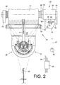
- This drive device 27, which is preferably designed as an electronically commutatable DC motor, is, as can be seen from FIGS. 2 to 4, integrated in a bearing housing 23 of the coil frame 18.
- a thread traversing device 28 For traversing the thread 30 during the winding process a thread traversing device 28 is provided. Such in Figure 2 indicated traversing device is for example in DE 198 58 548 A1 described in detail.
- the thread traversing device 28 consists essentially of a finger-like thread guide 29, which, by acts on an electromechanical drive 31, the Thread 30, as indicated in Figure 2, between the two End faces of the cheese 11 traversed.
- the thread 30 slides on during the laying by the thread guide 29 a guide ruler 32.
- stator 33 of the drive device 27 is in a sliding bush 35 set within the Bearing housing 23 axially displaceable, by a Anti-rotation device 36 is adjusted in a rotationally fixed manner, is guided.
- Spring elements 43 act on the sliding bush 35 and act on the sliding bush 35 in the direction of the coil frame center.
- An annular space 41 is arranged between the bearing housing 23 and the sliding bush 35 and is connected via a pneumatic line to an electromagnetic valve, preferably a 3/2-way valve 44.
- the 3/2-way valve 44 which has both a switching magnet 45 and a manual control 46, is in turn connected to a compressed air source 48 via a pneumatic line 47.
- the windings of the stator 33 of the electronically commutated drive device 27 are connected to a direct current source (not shown) via direct current lines 51, 52.
- a direct current source not shown
- the sleeve-receiving plate 38 With the rotor 53, which is supported in bearings 54, 55, the sleeve-receiving plate 38 is also connected in a rotationally fixed manner, which, in cooperation with the sleeve-receiving plate 38 ', fixes a sleeve 57 of the cheese 11 in a force-locking manner.
- the cross-wound bobbin 11 which is non-positively fixed between the sleeve receiving plates 38 and 38, is rotated by the drive device 27. That is, the sleeve receiving plate 38 connected to the rotor 53 of the drive device 27 rotates in the winding direction SR and takes the cross-wound sleeve 57 with it.
- the sleeve receiving plate 38 is acted upon by the spring elements 43 acting on the sliding bush 35 so strongly in the direction of the center of the bobbin frame that a reliable frictional connection between the sleeve receiving plates 38, 38 'and the bobbin case 57 both during acceleration of the bobbin 11 and during braking of the bobbin is guaranteed.
- the 3/2-way valve 44 is during of the winding operation in the switch position "0", that is, the between the sliding bush 35 and the bearing housing 23 arranged annular space 41 is depressurized.
- the drive device 27 When the cheese 11 has reached its prescribed diameter and needs to be replaced, the drive device 27 is first subjected to a braking current and the cheese 11 is electrically braked to a standstill by the braking torque which arises. Then, the 3/2-way valve 44, as shown in Figure 4, is switched to the switching position "I" so that the annular space 41 is connected to the compressed air source 48. The inflowing compressed air pushes the sliding bush 35 back against the spring force of the spring elements 43 into the bearing housing 43, so that the cross-wound bobbin 57 clamped between the sleeve receiving plates 38, 38 'comes out of contact with the sleeve receiving plates 38, 38'. The cheese 11 can now be easily removed from the bobbin frame 18.
- the 3/2-way valve 44 is usually controlled by the winding station computer 39, which is connected via a control line 50 to a switching magnet 45 of the solenoid valve 44.
- a manual actuation 46 is also provided on the 3/2-way valve 44, by means of which the valve 44 can be brought manually into the switching position "I" ,
- an abutment 49 is also arranged on the coil frame.
- a lever-like tool can be inserted into this abutment 49 and thus the sliding bush can also be moved into the bearing housing without compressed air, ie the coil frame can be manipulated in the sense of "opening".
- the lever tool corresponds to a corresponding approach on the sliding bush.
Landscapes
- Engineering & Computer Science (AREA)
- Textile Engineering (AREA)
- Winding Filamentary Materials (AREA)
- Spinning Or Twisting Of Yarns (AREA)
Applications Claiming Priority (2)
| Application Number | Priority Date | Filing Date | Title |
|---|---|---|---|
| DE10040106A DE10040106A1 (de) | 2000-08-17 | 2000-08-17 | Spulvorrichtung für eine Kreuzspulen herstellende Textilmaschine |
| DE10040106 | 2000-08-17 |
Publications (3)
| Publication Number | Publication Date |
|---|---|
| EP1184320A2 true EP1184320A2 (fr) | 2002-03-06 |
| EP1184320A3 EP1184320A3 (fr) | 2002-06-26 |
| EP1184320B1 EP1184320B1 (fr) | 2004-04-21 |
Family
ID=7652669
Family Applications (1)
| Application Number | Title | Priority Date | Filing Date |
|---|---|---|---|
| EP01112109A Expired - Lifetime EP1184320B1 (fr) | 2000-08-17 | 2001-05-17 | Dispositif de bobinage pour une machine textile qui produit des bobines à spires croisées |
Country Status (6)
| Country | Link |
|---|---|
| US (1) | US6530538B2 (fr) |
| EP (1) | EP1184320B1 (fr) |
| JP (1) | JP4388718B2 (fr) |
| CN (1) | CN1339396A (fr) |
| AT (1) | ATE264805T1 (fr) |
| DE (2) | DE10040106A1 (fr) |
Cited By (4)
| Publication number | Priority date | Publication date | Assignee | Title |
|---|---|---|---|---|
| EP2336064A3 (fr) * | 2009-12-16 | 2012-05-02 | Murata Machinery, Ltd. | Machine de bobinage de fil |
| ITMI20120479A1 (it) * | 2012-03-27 | 2013-09-28 | Savio Macchine Tessili Spa | Braccio portarocche per il supporto di una rocca in avvolgimento |
| WO2015055399A3 (fr) * | 2013-10-14 | 2015-06-18 | Oerlikon Textile Gmbh & Co. Kg | Dispositif permettant l'extrusion, l'étirage et l'enroulement d'un groupe de bandelettes de feuille |
| WO2019007729A1 (fr) * | 2017-07-05 | 2019-01-10 | SSM Schärer Schweiter Mettler AG | Dispositif d'enroulement doté d'un cylindre de soutien et unité de réglage de force d'appui ainsi que machine de traitement du fil |
Families Citing this family (20)
| Publication number | Priority date | Publication date | Assignee | Title |
|---|---|---|---|---|
| DE102004025519A1 (de) * | 2004-05-25 | 2005-12-15 | Saurer Gmbh & Co. Kg | Verfahren und Vorrichtung zum Betreiben einer Spuleinrichtung einer Kreuzspulen herstellenden Textilmaschine |
| GB0413125D0 (en) * | 2004-06-12 | 2004-07-14 | Chilcott Arthur | Roll drive arm |
| DE102004045747A1 (de) * | 2004-09-21 | 2006-03-23 | Saurer Gmbh & Co. Kg | Aufsteckdorn für eine Arbeitsstelle eines Kreuzspulautomaten |
| FR2887534B1 (fr) * | 2005-06-24 | 2007-11-16 | Saint Gobain Vetrotex | Bobinoir a course secondaire pilotee. |
| DE102006050140A1 (de) * | 2006-10-25 | 2008-04-30 | Oerlikon Textile Gmbh & Co. Kg | Spulenbremse für eine Spulvorrichtung einer Kreuzspulen herstellenden Textilmaschine |
| JP2009007110A (ja) * | 2007-06-27 | 2009-01-15 | Tmt Machinery Inc | 糸巻取装置 |
| JP2010058955A (ja) * | 2008-09-05 | 2010-03-18 | Murata Machinery Ltd | パッケージブレーキと、これを備えた自動ワインダ |
| DE102009004615A1 (de) * | 2009-01-15 | 2010-07-22 | Oerlikon Textile Gmbh & Co. Kg | Verfahren zum Betreiben einer Spulvorrichtung und Spulvorrichtung einer Auflaufspulen herstellenden Textilmaschine |
| CN102107800B (zh) * | 2011-03-14 | 2012-10-17 | 浙江寰亚电子有限公司 | 智能倒筒机 |
| JP2013067478A (ja) * | 2011-09-21 | 2013-04-18 | Murata Machinery Ltd | 糸巻取ユニット |
| JP2015147633A (ja) * | 2014-02-05 | 2015-08-20 | 村田機械株式会社 | ボビンセット装置、及び糸巻取機 |
| CN105883489A (zh) * | 2016-06-16 | 2016-08-24 | 际华三五四二纺织有限公司 | 一种改进型络筒机锥筒管托架装置 |
| DE102016117612A1 (de) * | 2016-09-19 | 2018-03-22 | Saurer Germany Gmbh & Co. Kg | Rahmenöffnungseinrichtung für einen Spulenrahmen |
| JP2018065637A (ja) * | 2016-10-18 | 2018-04-26 | 村田機械株式会社 | 糸巻取装置 |
| DE102018000259A1 (de) * | 2018-01-13 | 2019-07-18 | Oerlikon Textile Gmbh & Co. Kg | Adaptereinrichtung zum Halten zumindest einer Spulhülse |
| CN109502425A (zh) * | 2018-11-20 | 2019-03-22 | 广东溢达纺织有限公司 | 化纤纱上油槽筒式络筒机 |
| CN109466970B (zh) * | 2018-11-29 | 2021-04-06 | 象山邱工联信息技术有限公司 | 线缆收卷装置 |
| DE102020122682A1 (de) | 2020-08-31 | 2022-03-03 | Saurer Spinning Solutions Gmbh & Co. Kg | Spulenrahmen einer Spulvorrichtung einer Kreuzspulen herstellenden Textilmaschine |
| CN112340535A (zh) * | 2020-11-05 | 2021-02-09 | 安徽恒硕纺织品有限公司 | 一种具有排列功能的复合纺纱用收卷装置 |
| CN112645145A (zh) * | 2020-12-18 | 2021-04-13 | 福建永荣锦江股份有限公司 | 一种安全性高的自动绕线机 |
Family Cites Families (22)
| Publication number | Priority date | Publication date | Assignee | Title |
|---|---|---|---|---|
| US2016509A (en) * | 1931-04-30 | 1935-10-08 | Vaughn Machinery Co | Winding device |
| US2930538A (en) * | 1956-10-19 | 1960-03-29 | Whitin Machine Works | Stop motion for winding machine |
| US3381912A (en) * | 1965-11-26 | 1968-05-07 | William F. Huck | Core lockup and sidelay control device for splicing rollstands |
| DE2106898A1 (de) * | 1971-02-13 | 1972-08-24 | Siemens Ag | Spinnturbine mit einem drehzahlgeregelten, abbremsbaren elektrischen Antriebsmotor |
| CH523843A (de) * | 1971-03-04 | 1972-06-15 | Barmag Barmer Maschf | Spulvorrichtung mit Treibwalzenantrieb zum Aufwickeln endloser Fäden |
| DE2313152C2 (de) * | 1973-03-16 | 1984-09-27 | W. Schlafhorst & Co, 4050 Mönchengladbach | Vorrichtung an Spulenrahmen zum Stillsetzen eines Wickelkörpers |
| DE2458996A1 (de) * | 1974-12-13 | 1976-06-16 | Karlsruhe Augsburg Iweka | Regelanordnung, insbesondere an spulenspinnmaschinen |
| CH638377A5 (it) * | 1980-04-14 | 1983-09-30 | Luigi Pedroia | Macchina comprendente un meccanismo atto a determinare la rotazione del rocchetto portante la riserva di spago, in un involucro contenente il rocchetto, il tutto per legare carne insaccata in budella. |
| CH666063A5 (de) * | 1984-08-31 | 1988-06-30 | Benninger Ag Maschf | Wickelmaschine zum aufwickeln und/oder abwickeln bahnfoermig gefuehrten gutes. |
| JPS63267670A (ja) * | 1987-04-23 | 1988-11-04 | Murata Mach Ltd | 自動ワインダ− |
| DE3805662A1 (de) * | 1988-02-24 | 1989-09-07 | Skf Textilmasch Komponenten | Ringspinnmaschine |
| US4953590A (en) * | 1988-04-22 | 1990-09-04 | Tokyo Keiki Company Ltd. | Electromagnetic directional control valve |
| DE3927607A1 (de) * | 1988-08-29 | 1990-03-08 | Barmag Barmer Maschf | Spulvorrichtung |
| DE3911505C2 (de) * | 1989-04-08 | 1999-10-14 | Schlafhorst & Co W | Verfahren und Spulstelle zum Herstellen einer fehlerfreien Kreuzspule |
| DE4300389C2 (de) * | 1992-01-18 | 2001-02-08 | Barmag Barmer Maschf | Spulvorrichtung |
| DE9310332U1 (de) * | 1993-07-12 | 1993-09-02 | W. Schlafhorst AG & Co, 41061 Mönchengladbach | Vorrichtung zum automatischen Wickeln einer Fadenreserve |
| DE4330647A1 (de) * | 1993-09-10 | 1995-03-16 | Schlafhorst & Co W | Spulvorrichtung |
| DE4336312C2 (de) * | 1993-10-25 | 2003-09-25 | Schlafhorst & Co W | Vorrichtung zum Wickeln von Garnkörpern |
| US5906333A (en) * | 1997-04-16 | 1999-05-25 | Paper Converting Machine Company | Center drive unwind system |
| DE19836701A1 (de) * | 1998-08-13 | 2000-02-17 | Schlafhorst & Co W | Verfahren zum Stillsetzen eines elektrischen Antriebsmotors und Bremsschaltung |
| DE19858548A1 (de) | 1998-12-18 | 2000-06-21 | Schlafhorst & Co W | Fadenführer zum traversierenden Zuführen eines Fadens zu einer rotierend angetriebenen Auflaufspule |
| DE19908093A1 (de) * | 1999-02-25 | 2000-08-31 | Schlafhorst & Co W | Spulvorrichtung für eine Kreuzspulen herstellende Textilmaschine |
-
2000
- 2000-08-17 DE DE10040106A patent/DE10040106A1/de not_active Withdrawn
-
2001
- 2001-05-17 DE DE50102034T patent/DE50102034D1/de not_active Expired - Fee Related
- 2001-05-17 EP EP01112109A patent/EP1184320B1/fr not_active Expired - Lifetime
- 2001-05-17 AT AT01112109T patent/ATE264805T1/de not_active IP Right Cessation
- 2001-08-14 JP JP2001246270A patent/JP4388718B2/ja not_active Expired - Fee Related
- 2001-08-17 CN CN01133944A patent/CN1339396A/zh active Pending
- 2001-08-17 US US09/932,147 patent/US6530538B2/en not_active Expired - Fee Related
Cited By (5)
| Publication number | Priority date | Publication date | Assignee | Title |
|---|---|---|---|---|
| EP2336064A3 (fr) * | 2009-12-16 | 2012-05-02 | Murata Machinery, Ltd. | Machine de bobinage de fil |
| ITMI20120479A1 (it) * | 2012-03-27 | 2013-09-28 | Savio Macchine Tessili Spa | Braccio portarocche per il supporto di una rocca in avvolgimento |
| WO2015055399A3 (fr) * | 2013-10-14 | 2015-06-18 | Oerlikon Textile Gmbh & Co. Kg | Dispositif permettant l'extrusion, l'étirage et l'enroulement d'un groupe de bandelettes de feuille |
| US10730716B2 (en) | 2013-10-14 | 2020-08-04 | Oerlikon Textile Gmbh & Co. Kg | Device for extruding, stretching, and winding a group of film strips |
| WO2019007729A1 (fr) * | 2017-07-05 | 2019-01-10 | SSM Schärer Schweiter Mettler AG | Dispositif d'enroulement doté d'un cylindre de soutien et unité de réglage de force d'appui ainsi que machine de traitement du fil |
Also Published As
| Publication number | Publication date |
|---|---|
| EP1184320A3 (fr) | 2002-06-26 |
| US6530538B2 (en) | 2003-03-11 |
| JP4388718B2 (ja) | 2009-12-24 |
| US20020020779A1 (en) | 2002-02-21 |
| ATE264805T1 (de) | 2004-05-15 |
| CN1339396A (zh) | 2002-03-13 |
| DE50102034D1 (de) | 2004-05-27 |
| JP2002114445A (ja) | 2002-04-16 |
| DE10040106A1 (de) | 2002-02-28 |
| EP1184320B1 (fr) | 2004-04-21 |
Similar Documents
| Publication | Publication Date | Title |
|---|---|---|
| EP1184320B1 (fr) | Dispositif de bobinage pour une machine textile qui produit des bobines à spires croisées | |
| DE102008026777A1 (de) | Saugdüse | |
| EP0846640B1 (fr) | Machine textile pour la production de bobines à spires croisées | |
| DE102009004615A1 (de) | Verfahren zum Betreiben einer Spulvorrichtung und Spulvorrichtung einer Auflaufspulen herstellenden Textilmaschine | |
| DE102016115732A1 (de) | Fadenspleißvorrichtung für eine Arbeitsstelle einer Kreuzspulen herstellenden Textilmaschine | |
| DE19908093A1 (de) | Spulvorrichtung für eine Kreuzspulen herstellende Textilmaschine | |
| DE102008053246A1 (de) | Kreuzspulen herstellende Textilmaschine und Verfahren zum Betreiben der Textilmaschine | |
| DE102007036696A1 (de) | Kreuzspulenwechsler | |
| EP1076028B1 (fr) | Dispositif de rattachement du fil pour une machine textile fabriquant des bobines à spires croisées | |
| EP2388224A2 (fr) | Agrégat de commande | |
| EP1127831B1 (fr) | Dispositif de mise en service d'un poste de travail d'une machine textile pour la fabrication de bobines à spires croisées | |
| EP2097346B1 (fr) | Frein de bobine pour un dispositif de bobinage d'une machine textile qui fabrique des bobines croisées | |
| EP1971545B1 (fr) | Dispositif d'epissage de fils pour machine textile qui forme des bobines croisees | |
| DE10040109A1 (de) | Lagergehäuse für eine Antriebseinrichtung einer Kreuzspulen herstellenden Textilmaschine | |
| DE102008037992A1 (de) | Verfahren und Vorrichtung zum Betreiben einer Kopsentstaubungsanlage einer Kreuzspulen herstellenden Textilmaschine | |
| DE102007035430B4 (de) | Spulvorrichtung für eine Arbeitsstelle einer Offenend-Spinnmaschine | |
| DE10007949A1 (de) | Spulenrahmen für eine Textilmaschine | |
| EP0295394A1 (fr) | Méthode et dispositif de formation d'une réserve de fil | |
| DE10253527A1 (de) | Spulvorrichtung für eine Arbeitsstelle einer Kreuzspulen herstellenden Textilmaschine | |
| DE102017102438A1 (de) | Fadenspleißvorrichtung für eine Arbeitsstelle einer Kreuzspulen herstellenden Textilmaschine | |
| DE102005051935A1 (de) | Fadenverbindungsvorrichtung | |
| EP1302427A1 (fr) | Dispositif d'épissure de fils | |
| DE10336683A1 (de) | Spulstelle für eine Kreuzspulen herstellende Textilmaschine | |
| DE102007048719A1 (de) | Serviceaggregat | |
| DE102016123451A1 (de) | Fadenspleißvorrichtung |
Legal Events
| Date | Code | Title | Description |
|---|---|---|---|
| PUAI | Public reference made under article 153(3) epc to a published international application that has entered the european phase |
Free format text: ORIGINAL CODE: 0009012 |
|
| AK | Designated contracting states |
Kind code of ref document: A2 Designated state(s): AT BE CH CY DE DK ES FI FR GB GR IE IT LI LU MC NL PT SE TR |
|
| AX | Request for extension of the european patent |
Free format text: AL;LT;LV;MK;RO;SI |
|
| PUAL | Search report despatched |
Free format text: ORIGINAL CODE: 0009013 |
|
| AK | Designated contracting states |
Kind code of ref document: A3 Designated state(s): AT BE CH CY DE DK ES FI FR GB GR IE IT LI LU MC NL PT SE TR |
|
| AX | Request for extension of the european patent |
Free format text: AL;LT;LV;MK;RO;SI |
|
| 17P | Request for examination filed |
Effective date: 20021227 |
|
| AKX | Designation fees paid |
Designated state(s): AT CH DE IT LI TR |
|
| GRAP | Despatch of communication of intention to grant a patent |
Free format text: ORIGINAL CODE: EPIDOSNIGR1 |
|
| RAP1 | Party data changed (applicant data changed or rights of an application transferred) |
Owner name: SAURER GMBH & CO. KG |
|
| GRAS | Grant fee paid |
Free format text: ORIGINAL CODE: EPIDOSNIGR3 |
|
| GRAA | (expected) grant |
Free format text: ORIGINAL CODE: 0009210 |
|
| AK | Designated contracting states |
Kind code of ref document: B1 Designated state(s): AT CH DE IT LI TR |
|
| PG25 | Lapsed in a contracting state [announced via postgrant information from national office to epo] |
Ref country code: IT Free format text: LAPSE BECAUSE OF FAILURE TO SUBMIT A TRANSLATION OF THE DESCRIPTION OR TO PAY THE FEE WITHIN THE PRESCRIBED TIME-LIMIT;WARNING: LAPSES OF ITALIAN PATENTS WITH EFFECTIVE DATE BEFORE 2007 MAY HAVE OCCURRED AT ANY TIME BEFORE 2007. THE CORRECT EFFECTIVE DATE MAY BE DIFFERENT FROM THE ONE RECORDED. Effective date: 20040421 Ref country code: TR Free format text: LAPSE BECAUSE OF FAILURE TO SUBMIT A TRANSLATION OF THE DESCRIPTION OR TO PAY THE FEE WITHIN THE PRESCRIBED TIME-LIMIT Effective date: 20040421 |
|
| REG | Reference to a national code |
Ref country code: CH Ref legal event code: EP |
|
| PG25 | Lapsed in a contracting state [announced via postgrant information from national office to epo] |
Ref country code: AT Free format text: LAPSE BECAUSE OF NON-PAYMENT OF DUE FEES Effective date: 20040517 |
|
| REG | Reference to a national code |
Ref country code: IE Ref legal event code: FG4D Free format text: GERMAN |
|
| REF | Corresponds to: |
Ref document number: 50102034 Country of ref document: DE Date of ref document: 20040527 Kind code of ref document: P |
|
| PG25 | Lapsed in a contracting state [announced via postgrant information from national office to epo] |
Ref country code: DE Free format text: LAPSE BECAUSE OF NON-PAYMENT OF DUE FEES Effective date: 20041201 |
|
| REG | Reference to a national code |
Ref country code: IE Ref legal event code: FD4D |
|
| PLBE | No opposition filed within time limit |
Free format text: ORIGINAL CODE: 0009261 |
|
| STAA | Information on the status of an ep patent application or granted ep patent |
Free format text: STATUS: NO OPPOSITION FILED WITHIN TIME LIMIT |
|
| 26N | No opposition filed |
Effective date: 20050124 |
|
| PG25 | Lapsed in a contracting state [announced via postgrant information from national office to epo] |
Ref country code: CH Free format text: LAPSE BECAUSE OF NON-PAYMENT OF DUE FEES Effective date: 20050531 Ref country code: LI Free format text: LAPSE BECAUSE OF NON-PAYMENT OF DUE FEES Effective date: 20050531 |
|
| REG | Reference to a national code |
Ref country code: CH Ref legal event code: PL |