EP1184653B1 - Machine d'équilibrage et arrangement de compensation d'un balourd - Google Patents
Machine d'équilibrage et arrangement de compensation d'un balourd Download PDFInfo
- Publication number
- EP1184653B1 EP1184653B1 EP01120560A EP01120560A EP1184653B1 EP 1184653 B1 EP1184653 B1 EP 1184653B1 EP 01120560 A EP01120560 A EP 01120560A EP 01120560 A EP01120560 A EP 01120560A EP 1184653 B1 EP1184653 B1 EP 1184653B1
- Authority
- EP
- European Patent Office
- Prior art keywords
- rotor
- material removal
- fixing
- crankshaft
- balancing
- Prior art date
- Legal status (The legal status is an assumption and is not a legal conclusion. Google has not performed a legal analysis and makes no representation as to the accuracy of the status listed.)
- Expired - Lifetime
Links
- 239000000463 material Substances 0.000 claims abstract description 28
- 238000005553 drilling Methods 0.000 claims description 11
- 238000000034 method Methods 0.000 claims description 8
- 238000006073 displacement reaction Methods 0.000 claims description 6
- 238000001514 detection method Methods 0.000 abstract description 2
- 238000012545 processing Methods 0.000 description 8
- 238000003754 machining Methods 0.000 description 4
- 230000006978 adaptation Effects 0.000 description 3
- 238000011161 development Methods 0.000 description 2
- 238000005259 measurement Methods 0.000 description 2
- 239000003795 chemical substances by application Substances 0.000 description 1
- 238000013461 design Methods 0.000 description 1
- 229910003460 diamond Inorganic materials 0.000 description 1
- 239000010432 diamond Substances 0.000 description 1
- 238000011156 evaluation Methods 0.000 description 1
- 238000003801 milling Methods 0.000 description 1
- 238000009420 retrofitting Methods 0.000 description 1
- 230000000630 rising effect Effects 0.000 description 1
- 238000012546 transfer Methods 0.000 description 1
Images
Classifications
-
- G—PHYSICS
- G01—MEASURING; TESTING
- G01M—TESTING STATIC OR DYNAMIC BALANCE OF MACHINES OR STRUCTURES; TESTING OF STRUCTURES OR APPARATUS, NOT OTHERWISE PROVIDED FOR
- G01M1/00—Testing static or dynamic balance of machines or structures
- G01M1/14—Determining imbalance
- G01M1/16—Determining imbalance by oscillating or rotating the body to be tested
- G01M1/24—Performing balancing on elastic shafts, e.g. for crankshafts
-
- G—PHYSICS
- G01—MEASURING; TESTING
- G01M—TESTING STATIC OR DYNAMIC BALANCE OF MACHINES OR STRUCTURES; TESTING OF STRUCTURES OR APPARATUS, NOT OTHERWISE PROVIDED FOR
- G01M1/00—Testing static or dynamic balance of machines or structures
- G01M1/14—Determining imbalance
- G01M1/16—Determining imbalance by oscillating or rotating the body to be tested
- G01M1/26—Determining imbalance by oscillating or rotating the body to be tested with special adaptations for marking, e.g. by drilling
-
- G—PHYSICS
- G01—MEASURING; TESTING
- G01M—TESTING STATIC OR DYNAMIC BALANCE OF MACHINES OR STRUCTURES; TESTING OF STRUCTURES OR APPARATUS, NOT OTHERWISE PROVIDED FOR
- G01M1/00—Testing static or dynamic balance of machines or structures
- G01M1/30—Compensating imbalance
- G01M1/34—Compensating imbalance by removing material from the body to be tested, e.g. from the tread of tyres
Definitions
- the invention relates to a device for balancing an imbalance in a balancing machine for rotors having a plurality of bearings, in particular crankshafts, with a plurality of bearings of the rotor assignable storage facilities for supporting the rotor, with a material removal device and means for fixing the rotor during the balancing process.
- balancing machines for crankshafts is a balancing machine of the type specified, which is intended to determine the unbalance of finished crankshafts and to compensate for the determined unbalance.
- the vibrating frame supported oscillatably against the machine bed has a plurality of longitudinally displaceable and exchangeable bearing devices for receiving the crankshaft at suitable bearing points, for example at the outer and the central main bearing in a 4-cylinder crankshaft.
- Auswuchtmaschine backstops are provided which prevent the lifting of the crankshaft during rotation due to free moments of the crankshaft.
- a Bohrportal which is displaceable in the longitudinal direction of the crankshaft and has a displaceable in the radial direction, designed as a drilling device Materialentfemungs worn. It can not be ruled out in this known balancing machine that it comes to the movements of the stored crankshaft when drilling into the stored by its own weight crankshaft especially for lighter crankshafts.
- a device of the type specified in the preamble of claim 1 which has several Materialentfemungs wornen and several means for fixing the rotor during the balancing process, which are distributed over two processing stations.
- Each processing station includes a plurality of bearing blocks associated with the crankshaft bearings and a jaw pivotally mounted thereon and having a spring-biased tensioning piston for clamping a crankpin and tensioning shoes for clamping the crankshaft journal.
- the one processing station has two juxtaposed material removal means for removing material at the end portions of the crankshaft.
- a center Material removal device provided with two parallel tools that are used for processing the central counterweights of the crankshaft. With the aid of a transport device, the crankshafts to be balanced are transported one after the other from the processing station to the processing station.
- Out DE 43 34 244 A is a device for balancing different system imbalances in the balancing of rotors with unbalanced mass distribution, in particular unbalanced crankshaft known.
- a swivel weight is provided on one of the drive elements of the balancing machine, which can be rotated about the axis of rotation in order to bring about an adaptation to another system imbalance.
- a self-compensated crankshaft balancing unit which is divided into a measuring part and a compensation part, with the front of the machine bed the measuring unit with drive unit and two oscillating bearings for the crankshaft and built-in measurement, display and control devices and behind the compensation part is arranged.
- the compensation part consists of two vertical fixed boring mills and the support bearings for the shaft, as well as the associated clamping elements and a rotary unit.
- a transfer unit with two gripper levers connects the measuring part and the compensation part. Only one crankshaft version can be balanced with this machine.
- an unbalance measuring station in which the unbalance compensation can be made for example by drilling or milling.
- the bearing devices activated during the imbalance measuring operation the bearing devices closest to the imbalance compensation location are activated, so that an abutment is formed during machining.
- the compensation tool can be guided axially displaceably via longitudinal bars, A device for fixing the rotor is not present.
- the invention has for its object to provide a balancing machine and a device for balancing an imbalance, which is a flexible adaptation allows different rotors or crankshafts and in which regardless of the type of the stored rotors balancing accuracy is improved.
- the device according to the invention for compensating an imbalance is ensured that the removal of material on the rotor by, for example, drilling compensation holes without affecting the compensation process, in particular without damage to the tool or the workpiece, namely the rotor or the crankshaft, takes place because of the rotor a separate facility is detained. As a result, movements of the rotor are reliably prevented during the material removal process.
- the embodiment of the invention allows for the first time high-speed machining operations with carbide or diamond tipped tools in an imbalance compensation of rotors with multiple bearings, especially crankshafts. In addition, a precise material removal is guaranteed and associated with an accurate balancing result. Furthermore, a flexible adaptation to different rotors or crankshafts is possible.
- the device according to the invention also has the advantage that a suitable balancing point for unbalance compensation can be specified, which can lie in the axial direction either on one side or the other side of a rotor main bearing.
- the means for fixing the rotor has at least one clamping device assignable to a bearing device.
- This embodiment is particularly simple and inexpensive to produce and also has the advantage that the chip flow is not hindered. Furthermore, not quite straight crankshafts are pressed firmly in the processing area on the bearing device, which improves the machining conditions.
- one of the respective compensation level adjacent bearing device is provided as an abutment for the clamping arm.
- two mutually orthogonal linear guides are provided for mutual displacement of the material removal device and the fixing device, which allows the use of inexpensive commercial components.
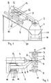
- FIG. 1 is a balancing machine 1 for rotors, in the illustrated case for crankshafts 2 shown schematically in a side view. Not shown are a drive device for the rotor, transducers and evaluation devices for the determination of the imbalance to be compensated, since common equipment is used here in the balancing area.
- the balancing machine 1 has a swing frame, which is supported by means not shown springs on the machine bed 30 vibratory.
- the oscillating frame has a plurality of, in the illustrated example, three bearing devices 3, 4, 5 for receiving the crankshaft 2 at designated bearing points of the crankshaft 2.
- it is a 4-cylinder crankshaft 2 with five possible bearings, of which the two outer bearings 10, 11 and the central bearing 12 are used for storage.
- the machine bed 30 is provided with means for removing the chips generated during the balancing operation; schematically illustrated are guide or collecting sheets 17 and associated therewith a chip conveyor 18 with a conveyor belt.
- the unbalance measurement with rotating rotor are not used for measuring the unbalance vibrations and angular position detection for the purpose of determining the imbalance to be compensated for size and angular position not shown.
- the balancing machine 1 has a device 6 for balancing the unbalance, which is designed as an assembly and has a material removal device 7 and a device 8 for fixing the rotor.
- the material removal device 7 is a drilling device whose drilling axis is arranged radially and transversely to the rotor axis.
- the device 8 for fixing the rotor has a clamping arm 9 with which the rotor is pressed against a bearing device 3, 4, 5 during the balancing process.
- the bearing device 3, 4, 5 is selected which is the intended one Compensation point or level is initially; in the FIG. 2
- the clamping arm 9 assumes the position shown.
- the drilling device can be moved in the longitudinal direction of the rotor in this compensation level.
- the material removal device 7 and the device 8 for fixing the rotor can be positioned independently of each other, in other words, their trajectories do not overlap.
- the device 6 is supported to compensate for imbalance as an assembly on the machine bed 30 and relative to the machine bed 30 slidably.
- the assembly can be displaced parallel to the rotor axis via a first linear guide 10, ie in the rotor longitudinal direction, and via a second linear guide 11 transversely to the rotor longitudinal direction and in the direction of the rotor axis.
- the first linear guide 10 can be in the example shown firmly mounted on the assembly material removal device 7, more precisely their drill, position in the proposed compensation level A, while on the second linear guide 11 of the drill in the radial direction for the purpose of material removal is displaceable; the drill is received in a drill spindle, which is usually longitudinally displaceable, so that the feed during drilling can be done via a feed of the drill spindle.
- the clamping arm 9 can be moved in the longitudinal direction so that it is positioned opposite the associated bearing device 4, while it is moved via the fourth linear guide 13 radially against the rotor bearing point 12, so that the rotor bearing point 12 to the bearing means 4 for Plant is brought.
- a fixed mounting of the device 8 for fixing the rotor to the module can be provided.
- a clamping cam 15 which is spatially fixed to the material removal device 7 and thus to the assembly, moves to a clamping cam 16 on the clamping arm 9 and a intervening spring 14 biases so that the voltage applied to the rotor clamping arm end pushes it with the force of the prestressed spring 14 against the bearing means 4 and so fixes the rotor while the removal of material is carried out.
- a longitudinally slightly curved crankshaft is so securely pressed against the bearing device and fixed.
- the tension arm 9 When balancing so first the drill and the clamping arm 9 are positioned in the axial direction and then moved radially for the purpose of material removal. Before the drill touches the rotor, the tension arm 9 has come into abutment with the rotor bearing 12 and pushes the rotor against the bearing means 4 by means of the increasing spring tension of the spring 14.
- a pressure medium operated cylinder e.g. a pneumatic cylinder, between the clamping cams 15, 16 are arranged. With it, the clamping force can be kept constant as with a rising over the displacement spring force.
- the actual drilling feed can be made via the longitudinally displaceable drilling spindle. The costs incurred during the compensation process chips fall down and are fed via Leit- or collecting sheets 15 a chip conveyor for removal.
- the compensation points are arranged by rotating the rotor in the intended angular position relative to the drill.
Landscapes
- Physics & Mathematics (AREA)
- General Physics & Mathematics (AREA)
- Testing Of Balance (AREA)
- Shafts, Cranks, Connecting Bars, And Related Bearings (AREA)
Claims (11)
- Dispositif (6) pour équilibrer un balourd dans une machine d'équilibrage (1) pour des pièces tournantes munies de plusieurs points d'appui, en particulier des vilebrequins (2), comportant plusieurs dispositifs d'appui (3, 4, 5), pouvant être associés aux points d'appui (10, 11, 12) d'une pièce tournante (2) et destinés à supporter la pièce tournante (2), un dispositif d'enlèvement de matière (7) et un dispositif (8) destiné à bloquer la pièce tournante (2) pendant le processus d'équilibrage, caractérisé en ce que le dispositif d'enlèvement de matière (7) et le dispositif (8) destiné à bloquer la pièce toumante (2) peuvent être positionnés indépendamment l'un de l'autre dans la direction longitudinale de la pièce tournante (2).
- Dispositif selon la revendication 1, caractérisé en ce que le dispositif (8) destiné à bloquer la pièce toumante comporte au moins un bras de serrage (9) à associer à un dispositif d'appui (3, 4, 5).
- Dispositif selon la revendication 2, caractérisé en ce que l'un des dispositifs d'appui (3 ou 4 ou 5), adjacent au plan d'équilibrage correspondant de la pièce toumante (2), fait fonction de contre-butée pour le bras de serrage (9).
- Dispositif selon la revendication 2 ou 3, caractérisé en ce que le bras de serrage (9) est sollicité par la force d'un ressort.
- Dispositif selon une ou plusieurs des revendications précédentes, caractérisé en ce que le dispositif d'enlèvement de matière (7) est conçu sous forme de dispositif de perçage.
- Dispositif selon une ou plusieurs des revendications précédentes, caractérisé en ce que le dispositif d'enlèvement de matière (7) et le dispositif (8) destiné à bloquer la pièce toumante forment un groupe modulaire.
- Dispositif selon l'une des revendications précédentes, caractérisé en ce que le dispositif d'enlèvement de matière (7) et le dispositif (8) destiné à bloquer la pièce toumante (2) peuvent être déplacés en translation, indépendamment l'un de l'autre, de préférence dans le plan d'usinage (B) contenant l'axe de la pièce tournante, le long de l'axe de la pièce toumante et radialement par rapport à l'axe de la pièce tournante.
- Dispositif selon la revendication 7, caractérisé en ce que pour le mouvement de translation, le dispositif d'enlèvement de matière (7) et le dispositif (8) destiné à bloquer la pièce tournante (2) sont munis chacun de deux guides linéaires (11, 12; 12, 13) disposés orthogonalement l'un par rapport à l'autre.
- Dispositif selon la revendication 6, caractérisé en ce que le groupe modulaire (6) est mis en appui sur la table (30) de la machine à équilibrer (1).
- Dispositif selon la revendication 9, caractérisé en ce que la mise en appui sur la table (30) est assurée par l'intermédiaire de guides linéaires (10, 11) intercalés.
- Dispositif selon une ou plusieurs des revendications précédentes, caractérisé en ce que le plan d'usinage (B) est incliné par rapport à la verticale.
Applications Claiming Priority (2)
| Application Number | Priority Date | Filing Date | Title |
|---|---|---|---|
| DE10042814 | 2000-08-30 | ||
| DE10042814A DE10042814A1 (de) | 2000-08-30 | 2000-08-30 | Auswuchtmaschine und Einrichtung zum Ausgleich einer Unwucht |
Publications (3)
| Publication Number | Publication Date |
|---|---|
| EP1184653A2 EP1184653A2 (fr) | 2002-03-06 |
| EP1184653A3 EP1184653A3 (fr) | 2003-01-22 |
| EP1184653B1 true EP1184653B1 (fr) | 2009-10-14 |
Family
ID=7654448
Family Applications (1)
| Application Number | Title | Priority Date | Filing Date |
|---|---|---|---|
| EP01120560A Expired - Lifetime EP1184653B1 (fr) | 2000-08-30 | 2001-08-29 | Machine d'équilibrage et arrangement de compensation d'un balourd |
Country Status (4)
| Country | Link |
|---|---|
| EP (1) | EP1184653B1 (fr) |
| JP (1) | JP4028194B2 (fr) |
| AT (1) | ATE445832T1 (fr) |
| DE (2) | DE10042814A1 (fr) |
Families Citing this family (5)
| Publication number | Priority date | Publication date | Assignee | Title |
|---|---|---|---|---|
| CN102172779B (zh) * | 2010-12-31 | 2014-05-21 | 哈尔滨东安汽车动力股份有限公司 | 全自动平衡去重机床工艺及其计算方法 |
| CN102998059B (zh) * | 2011-09-10 | 2015-03-18 | 湖北省天门泵业有限公司 | 渣浆泵盲孔零件加工动平衡装置 |
| CN111168122A (zh) * | 2020-01-10 | 2020-05-19 | 西安交通大学 | 一种适用于三缸曲轴的高精度全自动平衡机 |
| CN114646426B (zh) * | 2022-03-21 | 2023-02-14 | 孝感松林智能计测器有限公司 | 一种非对称曲轴双补偿自动平衡去重的方法 |
| CN115389103B (zh) * | 2022-10-08 | 2023-01-13 | 滨州鲁德曲轴有限责任公司 | 一种异形曲轴动态平衡性测定装置 |
Citations (2)
| Publication number | Priority date | Publication date | Assignee | Title |
|---|---|---|---|---|
| DE19601743A1 (de) * | 1996-01-19 | 1997-07-24 | Schleifmaschinenfabrik Aba Gmb | Vorrichtung zum Rundschleifen und Auswuchten |
| EP0803720A2 (fr) * | 1996-04-23 | 1997-10-29 | Schenck RoTec GmbH | Station de mesure du balourd |
Family Cites Families (8)
| Publication number | Priority date | Publication date | Assignee | Title |
|---|---|---|---|---|
| US2909948A (en) * | 1956-05-15 | 1959-10-27 | Tinius Olsen Testing Mach Co | Balancing equipment |
| FR2205999A5 (fr) * | 1972-11-03 | 1974-05-31 | Peugeot & Renault | |
| DE3638158A1 (de) * | 1986-11-08 | 1988-05-11 | Schenck Ag Carl | Unwuchtmessstation |
| US5505083A (en) * | 1993-04-23 | 1996-04-09 | Hines Industries, Inc. | Split station modular balancing and correction machine allowing early removal of workpiece |
| JPH06335801A (ja) * | 1993-05-24 | 1994-12-06 | Okuma Mach Works Ltd | バランス修正機能付数値制御旋盤 |
| DE4326790A1 (de) * | 1993-08-10 | 1995-02-16 | Konrad Kuerten | Ausgleicheinrichtung für die Unwucht an Rotationsteilen |
| DE4334244A1 (de) * | 1993-10-07 | 1995-04-13 | Schenck Ag Carl | Verfahren und Vorrichtung zum Ausgleich unterschiedlicher Systemunwuchten beim Auswuchten von Rotoren mit unsymmetrischer Massenverteilung |
| DE19645181B4 (de) * | 1996-11-02 | 2006-08-17 | Railion Deutschland Ag | Fertigungseinheit zum Drehen, Fräsen und Auswuchten |
-
2000
- 2000-08-30 DE DE10042814A patent/DE10042814A1/de not_active Withdrawn
-
2001
- 2001-08-29 DE DE50115170T patent/DE50115170D1/de not_active Expired - Lifetime
- 2001-08-29 JP JP2001259829A patent/JP4028194B2/ja not_active Expired - Fee Related
- 2001-08-29 EP EP01120560A patent/EP1184653B1/fr not_active Expired - Lifetime
- 2001-08-29 AT AT01120560T patent/ATE445832T1/de not_active IP Right Cessation
Patent Citations (2)
| Publication number | Priority date | Publication date | Assignee | Title |
|---|---|---|---|---|
| DE19601743A1 (de) * | 1996-01-19 | 1997-07-24 | Schleifmaschinenfabrik Aba Gmb | Vorrichtung zum Rundschleifen und Auswuchten |
| EP0803720A2 (fr) * | 1996-04-23 | 1997-10-29 | Schenck RoTec GmbH | Station de mesure du balourd |
Non-Patent Citations (1)
| Title |
|---|
| FEDERN K.; HACK H.: "Kurbelwellen-Auswuchtwerk mit selbstt{tigem Ausgleich", MTZ MOTORTECHNISCHE ZEITSCHRIFT, no. 5, 1 January 1952 (1952-01-01), VIEWEG VERLAG, WIESBADEN, DE, pages 121 - 123, XP009099381 * |
Also Published As
| Publication number | Publication date |
|---|---|
| DE10042814A1 (de) | 2002-03-14 |
| JP2002131167A (ja) | 2002-05-09 |
| DE50115170D1 (de) | 2009-11-26 |
| EP1184653A2 (fr) | 2002-03-06 |
| ATE445832T1 (de) | 2009-10-15 |
| JP4028194B2 (ja) | 2007-12-26 |
| EP1184653A3 (fr) | 2003-01-22 |
Similar Documents
| Publication | Publication Date | Title |
|---|---|---|
| DE19711317C2 (de) | Werkzeugmaschine | |
| EP2060375A1 (fr) | Machine de construction | |
| CH651240A5 (de) | Schleifmaschine. | |
| EP2361723A2 (fr) | Installation de traitement pour pièces à usiner avec un robot | |
| EP2150377B1 (fr) | Usinage sans vibrations de mandrins à pas de pèlerin | |
| WO2019052859A1 (fr) | Magasin à outils et procédé de changement d'outils | |
| DE102011102113A1 (de) | Mehrscheiben-Schleifmaschine mit zumindest zwei Spindelsätzen | |
| EP3338941B1 (fr) | Machine à transfert rotatif | |
| EP1035944A1 (fr) | Dispositif et procede pour la correction de faux-ronds | |
| DE10030087B4 (de) | Verfahren und Vorrichtung zum Vermessen und Bearbeiten von Werkstücken | |
| EP1184653B1 (fr) | Machine d'équilibrage et arrangement de compensation d'un balourd | |
| EP0278037B1 (fr) | Machine pour centrer l'équilibrage de corps en rotation | |
| DE19828239A1 (de) | Vorrichtung zum spanabhebenden Bearbeiten von Werkstücken | |
| EP1520161B1 (fr) | Dispositif et procede pour fixer des poids d'equilibrage sur des rotors, notamment sur des arbres de transmission ou des arbres a cardan | |
| EP1918049B1 (fr) | Procédé d'alésage de pièces à usiner avec une machine | |
| WO2021028205A1 (fr) | Machine de perçage en profondeur | |
| DE102019211997A1 (de) | Tiefbohrmaschine | |
| DE102022207743A1 (de) | Unwuchtmesseinrichtung, Bearbeitungseinrichtung, sowie Verfahren zur Bearbeitung eines Werkstücks | |
| EP0803720B1 (fr) | Station de mesure du balourd | |
| DE102007048083B4 (de) | Anordnung von Bearbeitungszonen | |
| WO2024156789A2 (fr) | Dispositif de mesure de balourd, dispositif d'usinage et procédé d'étalonnage du dispositif d'usinage, en particulier du dispositif de mesure de balourd | |
| EP3292932B1 (fr) | Ensemble à ressort permettant de générer la force de serrage d'un dispositif de serrage et dispositif de serrage pourvu d'un tel ensemble à ressort | |
| DE202019104405U1 (de) | Tiefbohrmaschine | |
| DE69410033T2 (de) | Mehrspindeldrehautomat | |
| WO2015169823A1 (fr) | Dispositif pour supporter à rotation des pièces, notamment des vilebrequins |
Legal Events
| Date | Code | Title | Description |
|---|---|---|---|
| PUAI | Public reference made under article 153(3) epc to a published international application that has entered the european phase |
Free format text: ORIGINAL CODE: 0009012 |
|
| AK | Designated contracting states |
Kind code of ref document: A2 Designated state(s): AT BE CH CY DE DK ES FI FR GB GR IE IT LI LU MC NL PT SE TR |
|
| AX | Request for extension of the european patent |
Free format text: AL;LT;LV;MK;RO;SI |
|
| PUAL | Search report despatched |
Free format text: ORIGINAL CODE: 0009013 |
|
| AK | Designated contracting states |
Kind code of ref document: A3 Designated state(s): AT BE CH CY DE DK ES FI FR GB GR IE IT LI LU MC NL PT SE TR |
|
| AX | Request for extension of the european patent |
Free format text: AL;LT;LV;MK;RO;SI |
|
| 17P | Request for examination filed |
Effective date: 20030519 |
|
| AKX | Designation fees paid |
Designated state(s): AT BE CH CY DE DK ES FI FR GB GR IE IT LI LU MC NL PT SE TR |
|
| 17Q | First examination report despatched |
Effective date: 20070904 |
|
| GRAP | Despatch of communication of intention to grant a patent |
Free format text: ORIGINAL CODE: EPIDOSNIGR1 |
|
| RIC1 | Information provided on ipc code assigned before grant |
Ipc: G01M 1/34 20060101ALI20090420BHEP Ipc: G01M 1/24 20060101AFI20090420BHEP Ipc: G01M 1/26 20060101ALI20090420BHEP |
|
| GRAS | Grant fee paid |
Free format text: ORIGINAL CODE: EPIDOSNIGR3 |
|
| GRAA | (expected) grant |
Free format text: ORIGINAL CODE: 0009210 |
|
| AK | Designated contracting states |
Kind code of ref document: B1 Designated state(s): AT BE CH CY DE DK ES FI FR GB GR IE IT LI LU MC NL PT SE TR |
|
| REG | Reference to a national code |
Ref country code: GB Ref legal event code: FG4D Free format text: NOT ENGLISH |
|
| REG | Reference to a national code |
Ref country code: CH Ref legal event code: EP |
|
| REG | Reference to a national code |
Ref country code: IE Ref legal event code: FG4D |
|
| REF | Corresponds to: |
Ref document number: 50115170 Country of ref document: DE Date of ref document: 20091126 Kind code of ref document: P |
|
| NLV1 | Nl: lapsed or annulled due to failure to fulfill the requirements of art. 29p and 29m of the patents act | ||
| PG25 | Lapsed in a contracting state [announced via postgrant information from national office to epo] |
Ref country code: ES Free format text: LAPSE BECAUSE OF FAILURE TO SUBMIT A TRANSLATION OF THE DESCRIPTION OR TO PAY THE FEE WITHIN THE PRESCRIBED TIME-LIMIT Effective date: 20100125 Ref country code: FI Free format text: LAPSE BECAUSE OF FAILURE TO SUBMIT A TRANSLATION OF THE DESCRIPTION OR TO PAY THE FEE WITHIN THE PRESCRIBED TIME-LIMIT Effective date: 20091014 Ref country code: SE Free format text: LAPSE BECAUSE OF FAILURE TO SUBMIT A TRANSLATION OF THE DESCRIPTION OR TO PAY THE FEE WITHIN THE PRESCRIBED TIME-LIMIT Effective date: 20091014 Ref country code: PT Free format text: LAPSE BECAUSE OF FAILURE TO SUBMIT A TRANSLATION OF THE DESCRIPTION OR TO PAY THE FEE WITHIN THE PRESCRIBED TIME-LIMIT Effective date: 20100215 |
|
| REG | Reference to a national code |
Ref country code: IE Ref legal event code: FD4D |
|
| PG25 | Lapsed in a contracting state [announced via postgrant information from national office to epo] |
Ref country code: DK Free format text: LAPSE BECAUSE OF FAILURE TO SUBMIT A TRANSLATION OF THE DESCRIPTION OR TO PAY THE FEE WITHIN THE PRESCRIBED TIME-LIMIT Effective date: 20091014 Ref country code: IE Free format text: LAPSE BECAUSE OF FAILURE TO SUBMIT A TRANSLATION OF THE DESCRIPTION OR TO PAY THE FEE WITHIN THE PRESCRIBED TIME-LIMIT Effective date: 20091014 |
|
| PLBE | No opposition filed within time limit |
Free format text: ORIGINAL CODE: 0009261 |
|
| STAA | Information on the status of an ep patent application or granted ep patent |
Free format text: STATUS: NO OPPOSITION FILED WITHIN TIME LIMIT |
|
| 26N | No opposition filed |
Effective date: 20100715 |
|
| PG25 | Lapsed in a contracting state [announced via postgrant information from national office to epo] |
Ref country code: GR Free format text: LAPSE BECAUSE OF FAILURE TO SUBMIT A TRANSLATION OF THE DESCRIPTION OR TO PAY THE FEE WITHIN THE PRESCRIBED TIME-LIMIT Effective date: 20100115 |
|
| BERE | Be: lapsed |
Owner name: SCHENCK ROTEC G.M.B.H. Effective date: 20100831 |
|
| PG25 | Lapsed in a contracting state [announced via postgrant information from national office to epo] |
Ref country code: MC Free format text: LAPSE BECAUSE OF NON-PAYMENT OF DUE FEES Effective date: 20100831 |
|
| REG | Reference to a national code |
Ref country code: CH Ref legal event code: PL |
|
| PG25 | Lapsed in a contracting state [announced via postgrant information from national office to epo] |
Ref country code: LI Free format text: LAPSE BECAUSE OF NON-PAYMENT OF DUE FEES Effective date: 20100831 Ref country code: CH Free format text: LAPSE BECAUSE OF NON-PAYMENT OF DUE FEES Effective date: 20100831 |
|
| PG25 | Lapsed in a contracting state [announced via postgrant information from national office to epo] |
Ref country code: BE Free format text: LAPSE BECAUSE OF NON-PAYMENT OF DUE FEES Effective date: 20100831 |
|
| PG25 | Lapsed in a contracting state [announced via postgrant information from national office to epo] |
Ref country code: AT Free format text: LAPSE BECAUSE OF NON-PAYMENT OF DUE FEES Effective date: 20100829 |
|
| PG25 | Lapsed in a contracting state [announced via postgrant information from national office to epo] |
Ref country code: CY Free format text: LAPSE BECAUSE OF FAILURE TO SUBMIT A TRANSLATION OF THE DESCRIPTION OR TO PAY THE FEE WITHIN THE PRESCRIBED TIME-LIMIT Effective date: 20091014 |
|
| PG25 | Lapsed in a contracting state [announced via postgrant information from national office to epo] |
Ref country code: LU Free format text: LAPSE BECAUSE OF NON-PAYMENT OF DUE FEES Effective date: 20100829 Ref country code: NL Free format text: LAPSE BECAUSE OF FAILURE TO SUBMIT A TRANSLATION OF THE DESCRIPTION OR TO PAY THE FEE WITHIN THE PRESCRIBED TIME-LIMIT Effective date: 20091014 |
|
| PG25 | Lapsed in a contracting state [announced via postgrant information from national office to epo] |
Ref country code: TR Free format text: LAPSE BECAUSE OF FAILURE TO SUBMIT A TRANSLATION OF THE DESCRIPTION OR TO PAY THE FEE WITHIN THE PRESCRIBED TIME-LIMIT Effective date: 20091014 |
|
| REG | Reference to a national code |
Ref country code: FR Ref legal event code: PLFP Year of fee payment: 16 |
|
| REG | Reference to a national code |
Ref country code: FR Ref legal event code: PLFP Year of fee payment: 17 |
|
| REG | Reference to a national code |
Ref country code: FR Ref legal event code: PLFP Year of fee payment: 18 |
|
| PGFP | Annual fee paid to national office [announced via postgrant information from national office to epo] |
Ref country code: FR Payment date: 20180824 Year of fee payment: 18 Ref country code: IT Payment date: 20180823 Year of fee payment: 18 |
|
| PGFP | Annual fee paid to national office [announced via postgrant information from national office to epo] |
Ref country code: GB Payment date: 20180828 Year of fee payment: 18 |
|
| PGFP | Annual fee paid to national office [announced via postgrant information from national office to epo] |
Ref country code: DE Payment date: 20181024 Year of fee payment: 18 |
|
| REG | Reference to a national code |
Ref country code: DE Ref legal event code: R119 Ref document number: 50115170 Country of ref document: DE |
|
| GBPC | Gb: european patent ceased through non-payment of renewal fee |
Effective date: 20190829 |
|
| PG25 | Lapsed in a contracting state [announced via postgrant information from national office to epo] |
Ref country code: FR Free format text: LAPSE BECAUSE OF NON-PAYMENT OF DUE FEES Effective date: 20190831 Ref country code: DE Free format text: LAPSE BECAUSE OF NON-PAYMENT OF DUE FEES Effective date: 20200303 |
|
| PG25 | Lapsed in a contracting state [announced via postgrant information from national office to epo] |
Ref country code: GB Free format text: LAPSE BECAUSE OF NON-PAYMENT OF DUE FEES Effective date: 20190829 Ref country code: IT Free format text: LAPSE BECAUSE OF NON-PAYMENT OF DUE FEES Effective date: 20190829 |