EP1186372A1 - Fraiseuse à portique - Google Patents
Fraiseuse à portique Download PDFInfo
- Publication number
- EP1186372A1 EP1186372A1 EP01810801A EP01810801A EP1186372A1 EP 1186372 A1 EP1186372 A1 EP 1186372A1 EP 01810801 A EP01810801 A EP 01810801A EP 01810801 A EP01810801 A EP 01810801A EP 1186372 A1 EP1186372 A1 EP 1186372A1
- Authority
- EP
- European Patent Office
- Prior art keywords
- portal
- linear guide
- machine
- machine bed
- guide
- Prior art date
- Legal status (The legal status is an assumption and is not a legal conclusion. Google has not performed a legal analysis and makes no representation as to the accuracy of the status listed.)
- Granted
Links
- 238000003801 milling Methods 0.000 title claims description 67
- 238000005266 casting Methods 0.000 claims description 15
- 239000000463 material Substances 0.000 claims description 7
- 238000013461 design Methods 0.000 claims description 5
- 230000005484 gravity Effects 0.000 claims description 4
- 238000010276 construction Methods 0.000 description 6
- 238000003754 machining Methods 0.000 description 4
- 238000009434 installation Methods 0.000 description 3
- 239000002986 polymer concrete Substances 0.000 description 3
- 238000012545 processing Methods 0.000 description 3
- 238000004519 manufacturing process Methods 0.000 description 2
- 101100004280 Caenorhabditis elegans best-2 gene Proteins 0.000 description 1
- 229910000831 Steel Inorganic materials 0.000 description 1
- 238000013459 approach Methods 0.000 description 1
- 230000015572 biosynthetic process Effects 0.000 description 1
- 230000000052 comparative effect Effects 0.000 description 1
- 230000002349 favourable effect Effects 0.000 description 1
- 230000001771 impaired effect Effects 0.000 description 1
- 230000003014 reinforcing effect Effects 0.000 description 1
- 239000007787 solid Substances 0.000 description 1
- 239000010959 steel Substances 0.000 description 1
- 238000012549 training Methods 0.000 description 1
Images

Classifications
-
- B—PERFORMING OPERATIONS; TRANSPORTING
- B23—MACHINE TOOLS; METAL-WORKING NOT OTHERWISE PROVIDED FOR
- B23Q—DETAILS, COMPONENTS, OR ACCESSORIES FOR MACHINE TOOLS, e.g. ARRANGEMENTS FOR COPYING OR CONTROLLING; MACHINE TOOLS IN GENERAL CHARACTERISED BY THE CONSTRUCTION OF PARTICULAR DETAILS OR COMPONENTS; COMBINATIONS OR ASSOCIATIONS OF METAL-WORKING MACHINES, NOT DIRECTED TO A PARTICULAR RESULT
- B23Q1/00—Members which are comprised in the general build-up of a form of machine, particularly relatively large fixed members
- B23Q1/01—Frames, beds, pillars or like members; Arrangement of ways
- B23Q1/012—Portals
-
- B—PERFORMING OPERATIONS; TRANSPORTING
- B23—MACHINE TOOLS; METAL-WORKING NOT OTHERWISE PROVIDED FOR
- B23Q—DETAILS, COMPONENTS, OR ACCESSORIES FOR MACHINE TOOLS, e.g. ARRANGEMENTS FOR COPYING OR CONTROLLING; MACHINE TOOLS IN GENERAL CHARACTERISED BY THE CONSTRUCTION OF PARTICULAR DETAILS OR COMPONENTS; COMBINATIONS OR ASSOCIATIONS OF METAL-WORKING MACHINES, NOT DIRECTED TO A PARTICULAR RESULT
- B23Q1/00—Members which are comprised in the general build-up of a form of machine, particularly relatively large fixed members
- B23Q1/01—Frames, beds, pillars or like members; Arrangement of ways
- B23Q1/017—Arrangements of ways
-
- B—PERFORMING OPERATIONS; TRANSPORTING
- B23—MACHINE TOOLS; METAL-WORKING NOT OTHERWISE PROVIDED FOR
- B23Q—DETAILS, COMPONENTS, OR ACCESSORIES FOR MACHINE TOOLS, e.g. ARRANGEMENTS FOR COPYING OR CONTROLLING; MACHINE TOOLS IN GENERAL CHARACTERISED BY THE CONSTRUCTION OF PARTICULAR DETAILS OR COMPONENTS; COMBINATIONS OR ASSOCIATIONS OF METAL-WORKING MACHINES, NOT DIRECTED TO A PARTICULAR RESULT
- B23Q11/00—Accessories fitted to machine tools for keeping tools or parts of the machine in good working condition or for cooling work; Safety devices specially combined with or arranged in, or specially adapted for use in connection with, machine tools
- B23Q11/0042—Devices for removing chips
- B23Q11/0053—Devices for removing chips using the gravity force
-
- B—PERFORMING OPERATIONS; TRANSPORTING
- B23—MACHINE TOOLS; METAL-WORKING NOT OTHERWISE PROVIDED FOR
- B23Q—DETAILS, COMPONENTS, OR ACCESSORIES FOR MACHINE TOOLS, e.g. ARRANGEMENTS FOR COPYING OR CONTROLLING; MACHINE TOOLS IN GENERAL CHARACTERISED BY THE CONSTRUCTION OF PARTICULAR DETAILS OR COMPONENTS; COMBINATIONS OR ASSOCIATIONS OF METAL-WORKING MACHINES, NOT DIRECTED TO A PARTICULAR RESULT
- B23Q7/00—Arrangements for handling work specially combined with or arranged in, or specially adapted for use in connection with, machine tools, e.g. for conveying, loading, positioning, discharging, sorting
- B23Q7/14—Arrangements for handling work specially combined with or arranged in, or specially adapted for use in connection with, machine tools, e.g. for conveying, loading, positioning, discharging, sorting co-ordinated in production lines
- B23Q7/1426—Arrangements for handling work specially combined with or arranged in, or specially adapted for use in connection with, machine tools, e.g. for conveying, loading, positioning, discharging, sorting co-ordinated in production lines with work holders not rigidly fixed to the transport devices
- B23Q7/1431—Work holder changers
Definitions
- the invention relates to a portal milling machine, i.e. a milling machine in portal design, according to the preamble of the independent claims.
- Portal milling machines of the type mentioned are generally known. You point a machine bed and a portal firmly connected to the machine bed. At the Portal, usually two vertical, firmly connected to the machine bed below Stand and a crossbar connecting these stands together, is a milling unit translationally provided with a milling spindle or a tool spindle in a first direction (Z) and a second direction (Y) transverse to that through the Portal passage defined machine longitudinal direction (X) arranged movable. Further have portal milling machines of the type mentioned firmly connected to the machine bed flat linear guide. This is essentially horizontal in the machine longitudinal direction (X), i.e. arranged in the X direction.
- Carriage which is a workpiece clamping device, typically in the form of a Workpiece table, carries.
- Such portal milling machines are usually designed in this way and arranged that the translatory movement direction X in Essentially horizontally through the portal, the translatory direction of movement Z essentially vertical and the translatory direction of movement Y im Run essentially horizontally and at right angles to the X direction.
- portal milling machines Compared to single-column milling machines in a C design, which is a single one, essentially have vertical stands on the top of which carries the milling unit Cantilever arm is attached and which is firmly connected to the machine bed below, which carries a workpiece table, portal milling machines have advantages in terms of the rigidity of the machine.
- the self-contained structure from the portal and the machine bed can absorb greater forces than the same dimension the one-sided open structure of a single-column machine in C design.
- portal milling machines are less suitable for automated operation as single-column machines in C design.
- the chip removal is problematic because the chips generated during milling tend to on the linear guide leading through the portal or on its Chip guard cover to stay seated.
- the portal Accessibility to the tool intervention point located in the area of the portal (English “tool processing point") and thus to the tool and the workpiece limited.
- the object of the invention is to provide a milling machine in portal construction, which can be easily automated and in particular good accessibility to the tool engagement point guaranteed as well as a good chip removal.
- a portal milling machine has an elongated machine bed whose longitudinal direction is an X direction (also called the machine longitudinal direction designated) defined.
- the portal milling machine is further at right angles to the X direction arranged portal provided, which has an elongated plan shape, the Longitudinal direction a Y direction (perpendicular to the X direction) (also as Portal longitudinal direction) defined.
- a milling unit on the portal is translational movable in a first direction and a second direction transverse to the X direction arranged, and on the machine bed is one in the X direction through the portal leading linear guide for a workpiece clamping device, in the X direction movable carriage attached.
- the floor plan shows a section of the machine bed on at least one side in the X direction beyond the portal, whereby this protruding part of the machine bed is also the whole Machine bed can act.
- the machine bed is in relation to the portal is arranged offset in the Y direction towards a longitudinal end of the portal, that in the area between the above machine bed section and the Portal included angle good from the other longitudinal end of the portal Accessibility to the working area of the machine in the area of the portal center is guaranteed is.
- the machine bed can be preferably more than a sixth in relation to the center of the portal even by more than two sixths of the clear width of the portal passage in Y direction to the one longitudinal end of the portal may be arranged offset in order To create enough space for the area of the other end of the portal.
- a portal milling machine it is asymmetrical Construction the portal with respect to the machine bed arranged so that the structure essentially formed from the portal and the machine bed Has floor plan shape in the manner of a two-legged right angle, with a Leg through the machine bed plan extending in the X direction and the others is formed by the portal floor plan extending in the Y direction.
- the machine bed is completely in the Y direction to a longitudinal end of the Portal offset arranged, and it is only on one portal side in the X direction beyond the portal. This makes it particularly easy overall and compact structure of the machine.
- the linear guide is an im Essentially horizontally arranged (i.e. running in the horizontal direction), flat linear guide, the guide plane of the linear guide with respect to the horizontal is inclined transversely to the X direction by an angle such that when milling resulting chips solely due to the gravity of the linear guide or a cover that protects the chips from falling down.
- a linear guide is used (also referred to as linear guidance) a bearing for guiding linearly moved Parts understood.
- a linear guide is said to be flat if it is in one Longitudinal guide plane extending management level defined.
- level guide bed becomes the management level determined by the guide bed surface.
- the guide bed surface needs not to be perfectly flat, but it can be made with passages, recesses, Reinforcing ribs or similar structures may be provided in sections deviate from the flat shape of the guide bed surface.
- a linear guide which essentially comprises a single, flat guideway (e.g.
- the track surface can be used as a guide level the linear guide.
- a linear guide includes two parallel rails or slideways, can be through the two parallel rails or slideways certain level are referred to as the management level. If one Linear guide as a profile rail guide with an essentially flat profile surface is formed, on which a plurality of parallel guide rails are attached are, this profile surface can be referred to as the guide level of the linear guide become.
- the strong inclination of the management level also creates the opportunity a possible workpiece changing device arranged to the side of the linear guide closer to the carriage carrying the workpiece jig, i.e. the X-slide, to be arranged as with a flat linear guide with a horizontal guide plane it is possible. This can shorten the times for workpiece changes become, which leads to an increase in the productivity of the portal milling machine according to the invention contributes.
- the inclination of the guide bed or the management level Linear guide created the possibility of carrying the workpiece clamping device To assemble sleds at different heights in a comparatively simple way.
- the portal milling machine according to the invention can be processed better of workpieces with different dimensions.
- the inclination of the guide level of the linear guide offers the possibility of Sled with the workpiece jig despite that from the center of the portal to one Machine bed offset towards the end of the portal through the center of the portal (and thus through an area favorable for workpiece machining) install by sliding the carriage essentially sideways on the linear guide is arranged.
- the guide plane of the linear guide is preferably transverse with respect to the horizontal inclined to the X direction by an angle that is greater than 40 degrees, preferably even is greater than 60 degrees. In particular, this angle can also be approximately 90 degrees.
- a rather small angle of inclination is used, for example about 45 degrees preferred. Due to a comparatively small inclination of the The management level becomes a better support for the heavy carriage on the linear guide guaranteed.
- larger angles of inclination are used preferred to ensure that the chips slide off the linear guide or to ensure their chip protection cover.
- an angle of 90 degrees can be used.
- the guide plane or the guide bed of the linear guide are arranged vertically.
- variants of the invention are also possible in which the management level of the Linear guide inclined at an angle to the horizontal transverse to the X direction that is greater than 90 degrees.
- the management level or the management bed are then overhanging, so that the X-carriage is hanging on the linear guide to be led.
- the linear guide is particularly good falling chips protected.
- the linear guide is preferred in a portal milling machine according to the invention designed in such a way that the X-slide can be positioned at different heights on the Linear guide can be mounted.
- This enables easy adjustment of the Portal milling machine for processing workpieces with different sizes.
- tables with different processing heights can be used for this purpose to be assembled.
- a portal milling machine can have a further slide (Y slide) have, which can be moved transversely to the X direction on the portal in the horizontal Y direction is arranged, which is movable on this Y-carriage in the vertical Z-direction Milling unit in the form of a headstock with a milling spindle is arranged.
- This embodiment of the invention is particularly suitable for High-speed milling, because to move the headstock just comparative small masses are to be moved.
- an inventive one Portal milling machine also a portal with a vertical Z-direction include movable cross member on which a headstock movable in the Y direction is arranged.
- a portal milling machine with a portal on which a milling unit translates in a first Direction (Z) and a second direction (Y) transverse to the machine longitudinal direction (X) is arranged movable, and an elongated machine bed, on which one in Essentially horizontally in the machine longitudinal direction (X) through the portal leading flat linear guide for a workpiece clamping device carrying X-directional slide is attached, which comes from the machine bed and the structure formed as a monolithic, homokinetic block (also called Called monoblock).
- the training of the machine bed and that Portal-wide structure as a monoblock ensures good heat conduction between the different structural parts and good rigidity of the structure.
- a such portal milling machine with monoblock structure can of course also with a strongly inclined guide plane of the planes extending in the X direction Linear guide and / or with one in relation to the center of the portal Longitudinal portal end offset machine bed.
- the aspect the formation of the structure comprising the machine bed and the portal as However, monoblock also proves to be independent of the strong inclination of the Guide level of the plane linear guide extending in the X direction or in relation to the center of the portal offset arrangement of the machine bed as advantageous.
- the entire monoblock is preferred in a portal milling machine with a monoblock structure made of polymer concrete.
- suitable materials such as Steel.
- the monoblock structure can be composed of individual cast parts. there the individual cast parts can be made from a uniform casting material, where possible after assembling the individual castings to the desired Structure between the castings existing gaps with the same Cast material are poured out to a homogeneous connection in terms of material to create between the castings. This way you can also make complicated ones Create monoblock structures.
- the portal is preferably designed as a one-piece casting in which the is also used as a one-piece casting machine bed, wherein the machine bed is designed as a carrier on which the linear guide is attached is. In this way, it can be done in a relatively simple and inexpensive manner Manufacture portal milling machines with different lengths of X guides or X strokes.
- the whole of the Machine bed and the structure formed the portal formed as a one-piece casting his. This enables an extremely simple manufacture of this structure.
- the structure has particularly good rigidity and thermal conductivity reached.
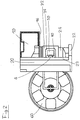
- the portal milling machine shown in Figures 1 and 2 comprises a machine bed 10, which is essentially the shape of an elongated cuboid with a bottom side, one Has ceiling side, two long sides and two end faces.
- the cuboid machine bed 10 is arranged on a solid base (not shown), that the bottom and top sides are horizontal and the long and the front sides stand vertically.
- the longitudinal direction of the machine bed 10 (also as the machine longitudinal direction is hereinafter referred to as the X direction in FIGS. 1 and 2 shown portal milling machine.
- a portal 20 is arranged in the region of one longitudinal end of the machine bed, the fixed to the machine bed 10 arranged at right angles to the machine bed 10 is.
- the portal 20 comprises a short stand 21 in the area of the portal Longitudinal end of the machine bed 10 on the ceiling side of the cuboid Machine bed 10 is placed.
- the portal 20 also includes a long one Stand 22, which is longer by the cuboid height of the machine bed 10 than the short one Stand 21.
- the two stands 21, 22 are essentially parallel to one another, vertical standing and at a distance from each other. You are in the field of theirs upper ends firmly connected by an elongated cross member 23, the horizontal and perpendicular to the longitudinal direction of the machine bed 10 (i.e. to the X direction) arranged and both fixed to the long support 22 and fixed to the short carrier 21 is connected.
- the longitudinal direction of the cross member 23 is as follows referred to as the Y direction of the machine shown in FIGS. 1 and 2.
- the base crossbar 24 In the region of the lower end of the long stand 22 there is an elongated one Crossbar 24 (hereinafter referred to as base crossbar 24) on one of them Long ends firmly attached.
- the other longitudinal end of this base cross member 24 is on the long side 12 of the machine bed 10 facing the long stand (hereinafter referred to as the inner longitudinal side 12 of the machine bed 10), in a lower one Area of the same, firmly attached.
- the base cross member 24 is essentially parallel arranged to the cross member 23 of the portal and thus extends in the Y direction. she creates a firm connection between the foot of the long stand 22 and the cuboid machine bed 10.
- the two stands 21, 22, the cross member 23, the machine bed 10 and the base crossbeam 24 has an annular closed structure, which has an X-direction running, essentially rectangular passage (hereinafter as Portal passage) limited.
- This portal passage is shown below by the Base cross member 24, on one side by the long stand 22, on the other Page through the machine bed 10 and the short stand 21 and above through the Cross member 23 limited.
- the base cross member 24 is formed as a monolithic, homokinetic block, i.e. as a monoblock.
- the entire monoblock is made of polymer concrete.
- the monoblock shown in FIGS. 1-2 is composed of several components, which are initially manufactured as one-piece castings and then to form the monoblock shown in FIGS. 1-2, where the spaces between the individual components were filled with polymer concrete were used to firmly connect the components together and create a monolithic structure to build.
- the structure formed from the portal 20 and the machine bed 10 has - as best 2 can be seen - essentially a floor plan in the manner of a two-leg angle.
- One leg of this angular shape is through the floor plan of the machine bed 10, the other through the floor plan of the portal 20.
- Die Portal side lying on the outside of the angle is subsequently called the back of the portal 20, while the portal side lying on the inside of the angle (from which the machine bed 10 distanced itself from the portal 20 Longitudinal end extends) is referred to as the front of the portal 20.
- the X guide comprises two parallel guide rails that extend in the X direction 14, 16, which one above the other on the vertical inner longitudinal side 12 of the machine bed 10 are firmly attached and define the management level of the X-guide. at the X-guide is therefore a flat linear guide with a vertical guide level.
- the guide rails 14, 16 of the X guide serve to guide one in the X direction movable carriage 30 (X-carriage 30), which is designed as a workpiece table 30 and is provided with a clamping device 32 for clamping workpieces 34.
- the guide rails 14, 16 are in this way in an upper region of the inner longitudinal side 12 of the machine bed 10 arranged that the X-slide 30 above the Base cross member 24 and can be moved over it through the portal 20.
- the direction of movement of the X slide is indicated by the double arrow 2.
- the Drive means (not shown) for moving the X-carriage 30 along the X-guide can be a drive spindle, a linear motor or another for linear motion axes Common drive devices include.
- the X-slide 30 has an underside which slopes upwards from the X-guide 36. This gives, even if the X-slide 30 directly in the portal passage is positioned, a space between the bottom 36 of the X-slide 30, the long stand 22 and the base cross member 24 of the portal 20. In the area of this free space a channel 26 extending in the X direction is formed in the base cross member 24, the one for receiving a chip conveyor (not shown) e.g. in shape a conveyor belt is provided.
- a linear guide running in the Y direction (hereinafter referred to as Y-guide) arranged.
- the Y-guide has two parallel, extending in the Y-direction guide rails, which one above the other the vertical front of the cross member 23 of the portal 20 are fixedly attached.
- the Y guide serves to guide a carriage 40 (Y carriage which can be moved in the Y direction 40), on which a with respect to the Y-carriage 40 in the vertical direction (also as Z direction)) movable milling unit 50 in the form of a with a milling spindle 52 provided headstock 50 is arranged.
- the directions of movement of the Y-slide 40 and the headstock 50 are indicated by the double arrows 4 and 6, respectively specified.
- the drive means (not shown) for moving the Y-carriage 40 and the headstock 50 in the Y or Z direction can in turn be a drive spindle, a linear motor or other drive devices commonly used for linear axes of motion include.
- the construction of the portal milling machine described above and shown in FIGS. 1-2 enables a workpiece clamped on the workpiece table 30 34 in the area of the inside angle of the angular plan structure of the machine to edit.
- the tool engagement point is thus in an area where the Machine has optimal rigidity.
- this machine construction good accessibility to the tool engagement point is guaranteed because the Tool engagement point is only on the two defined by the angle leg Sides surrounded by the machine, while by the remaining two sides is freely accessible for an operator.
- the portal milling machine shown in FIGS. 1-2 further with a tool magazine and an automatic tool changing device can be equipped as they are common for milling machines.
- a suitable tool magazine including a tool changer
- the tool magazine and the Tool changers can e.g. on the part of the machine bed leading away from the portal 10 can be installed.
- the automated workpiece changing magazine 60 can thereby be a fully automatic Operation of the portal milling machine shown in Figures 1-2 can be achieved.
- the invention is a portal milling machine is specified, which has a good chip removal and good accessibility to the Tool engagement point guaranteed.
Landscapes
- Engineering & Computer Science (AREA)
- Mechanical Engineering (AREA)
- Machine Tool Units (AREA)
Priority Applications (1)
| Application Number | Priority Date | Filing Date | Title |
|---|---|---|---|
| EP01810801A EP1186372B1 (fr) | 2000-09-08 | 2001-08-20 | Fraiseuse à portique |
Applications Claiming Priority (3)
| Application Number | Priority Date | Filing Date | Title |
|---|---|---|---|
| EP00810809A EP1186371A1 (fr) | 2000-09-08 | 2000-09-08 | Fraiseuse du type à portique |
| EP00810809 | 2000-09-08 | ||
| EP01810801A EP1186372B1 (fr) | 2000-09-08 | 2001-08-20 | Fraiseuse à portique |
Publications (2)
| Publication Number | Publication Date |
|---|---|
| EP1186372A1 true EP1186372A1 (fr) | 2002-03-13 |
| EP1186372B1 EP1186372B1 (fr) | 2008-12-17 |
Family
ID=26074009
Family Applications (1)
| Application Number | Title | Priority Date | Filing Date |
|---|---|---|---|
| EP01810801A Expired - Lifetime EP1186372B1 (fr) | 2000-09-08 | 2001-08-20 | Fraiseuse à portique |
Country Status (1)
| Country | Link |
|---|---|
| EP (1) | EP1186372B1 (fr) |
Cited By (8)
| Publication number | Priority date | Publication date | Assignee | Title |
|---|---|---|---|---|
| US5334243A (en) * | 1993-05-04 | 1994-08-02 | The Dow Chemical Company | Crack inhibitor for tape joint compositions |
| EP1747843A1 (fr) | 2005-07-30 | 2007-01-31 | Maschinenfabrik Berthold Hermle Aktiengesellschaft | Machine-outil avec dispositif pour changer les pièces a ousiner |
| FR2890325A1 (fr) * | 2005-09-06 | 2007-03-09 | Thibaut Soc Par Actions Simpli | Machine-outil munie d'un dispositif de preparation au bridage en temps masque, utilisant des ventouses double face |
| EP2623255A1 (fr) * | 2012-02-06 | 2013-08-07 | DECKEL MAHO Pfronten GmbH | Machine-outil universelle avec espace de collecte des copeaux |
| CN112792385A (zh) * | 2021-02-10 | 2021-05-14 | 宁波昌成数控机械有限公司 | 长行程高精度数控龙门铣床 |
| CN114833593A (zh) * | 2022-06-14 | 2022-08-02 | 江苏贵钰航空工业有限公司 | 一种数控机床门梁与滑座的多点承靠固定安装方法 |
| CN114871477A (zh) * | 2022-06-02 | 2022-08-09 | 涡阳县幸福门业有限公司 | 铝合金门窗顺水孔自动化加工装置及铝合金门窗加工系统 |
| CN116810931A (zh) * | 2023-08-18 | 2023-09-29 | 佛山市顺德区一涵机械制造有限公司 | 一种双端铣机床 |
Families Citing this family (2)
| Publication number | Priority date | Publication date | Assignee | Title |
|---|---|---|---|---|
| DE102012001621A1 (de) * | 2012-01-30 | 2013-08-01 | Heyligenstaedt Werkzeugmaschinen GmbH | Werkzeugmaschine mit einem Querbalken |
| CN105345122A (zh) * | 2015-11-30 | 2016-02-24 | 安徽天思朴超精密模具股份有限公司 | 切割机 |
Citations (8)
| Publication number | Priority date | Publication date | Assignee | Title |
|---|---|---|---|---|
| DE2521036A1 (de) * | 1975-05-12 | 1976-11-18 | Deckel Ag Friedrich | Werkzeugmaschinenbett aus beton o.dgl. und verfahren zur herstellung desselben |
| EP0405111A2 (fr) * | 1989-06-30 | 1991-01-02 | Boehringer Werkzeugmaschinen GmbH | Bâti de machine-outil avec porte-à-faux |
| DE4015570A1 (de) * | 1990-05-15 | 1991-11-21 | Doerries Scharmann Gmbh | Werkzeugmaschine, insbesondere vertikal-schleifmaschine und verfahren zum bearbeiten von werkstuecken mit dieser maschine |
| US5294220A (en) * | 1993-06-22 | 1994-03-15 | Ohmstede, Inc. | Machining apparatus |
| JPH0691457A (ja) * | 1992-09-10 | 1994-04-05 | Okuma Mach Works Ltd | 工作機械のベッド構造 |
| DE4242906A1 (de) * | 1992-12-18 | 1994-06-23 | Walter Ag | Numerisch gesteuerte Schleifmaschine zum Schleifen von metallischen Werkstücken, insbesondere Werkzeugen |
| US5674169A (en) * | 1982-09-28 | 1997-10-07 | Yang; Tai-Her | Tunnel type or dragon-gate type processing system assembled with selected elements and its related interface means |
| JPH10286734A (ja) * | 1997-04-11 | 1998-10-27 | Toshiba Mach Co Ltd | 門形工作機械 |
-
2001
- 2001-08-20 EP EP01810801A patent/EP1186372B1/fr not_active Expired - Lifetime
Patent Citations (8)
| Publication number | Priority date | Publication date | Assignee | Title |
|---|---|---|---|---|
| DE2521036A1 (de) * | 1975-05-12 | 1976-11-18 | Deckel Ag Friedrich | Werkzeugmaschinenbett aus beton o.dgl. und verfahren zur herstellung desselben |
| US5674169A (en) * | 1982-09-28 | 1997-10-07 | Yang; Tai-Her | Tunnel type or dragon-gate type processing system assembled with selected elements and its related interface means |
| EP0405111A2 (fr) * | 1989-06-30 | 1991-01-02 | Boehringer Werkzeugmaschinen GmbH | Bâti de machine-outil avec porte-à-faux |
| DE4015570A1 (de) * | 1990-05-15 | 1991-11-21 | Doerries Scharmann Gmbh | Werkzeugmaschine, insbesondere vertikal-schleifmaschine und verfahren zum bearbeiten von werkstuecken mit dieser maschine |
| JPH0691457A (ja) * | 1992-09-10 | 1994-04-05 | Okuma Mach Works Ltd | 工作機械のベッド構造 |
| DE4242906A1 (de) * | 1992-12-18 | 1994-06-23 | Walter Ag | Numerisch gesteuerte Schleifmaschine zum Schleifen von metallischen Werkstücken, insbesondere Werkzeugen |
| US5294220A (en) * | 1993-06-22 | 1994-03-15 | Ohmstede, Inc. | Machining apparatus |
| JPH10286734A (ja) * | 1997-04-11 | 1998-10-27 | Toshiba Mach Co Ltd | 門形工作機械 |
Non-Patent Citations (4)
| Title |
|---|
| JACKISCH U-V ET AL: "MINERALGUSS-GERECHTE MASCHINEN KONSTRUKTION", WERKSTATT UND BETRIEB, CARL HANSER VERLAG. MUNCHEN, DE, vol. 133, no. 1/2, February 2000 (2000-02-01), pages 51 - 52, XP000912386, ISSN: 0043-2792 * |
| PATENT ABSTRACTS OF JAPAN vol. 018, no. 354 (M - 1632) 5 July 1994 (1994-07-05) * |
| PATENT ABSTRACTS OF JAPAN vol. 1999, no. 01 29 January 1999 (1999-01-29) * |
| PUSH A V ET AL: "CHOOSING THE ARRANGEMENTS OF DOUBLE-HEAD LATHES", RUSSIAN ENGINEERING RESEARCH, ALLERTON PRESS, NEW YORK, US, vol. 14, no. 3, 1994, pages 50 - 60, XP000523922, ISSN: 1068-798X * |
Cited By (11)
| Publication number | Priority date | Publication date | Assignee | Title |
|---|---|---|---|---|
| US5334243A (en) * | 1993-05-04 | 1994-08-02 | The Dow Chemical Company | Crack inhibitor for tape joint compositions |
| EP1747843A1 (fr) | 2005-07-30 | 2007-01-31 | Maschinenfabrik Berthold Hermle Aktiengesellschaft | Machine-outil avec dispositif pour changer les pièces a ousiner |
| US7721398B2 (en) | 2005-07-30 | 2010-05-25 | Maschinenfabrik Berthold Hermle Ag | Cutting machine with a workpiece changer |
| FR2890325A1 (fr) * | 2005-09-06 | 2007-03-09 | Thibaut Soc Par Actions Simpli | Machine-outil munie d'un dispositif de preparation au bridage en temps masque, utilisant des ventouses double face |
| WO2007028886A1 (fr) * | 2005-09-06 | 2007-03-15 | Thibaut | Machine-outil munie d’un dispositif de preparation au bridage en temps masque, utilisant des ventouses double face |
| EP2623255A1 (fr) * | 2012-02-06 | 2013-08-07 | DECKEL MAHO Pfronten GmbH | Machine-outil universelle avec espace de collecte des copeaux |
| CN112792385A (zh) * | 2021-02-10 | 2021-05-14 | 宁波昌成数控机械有限公司 | 长行程高精度数控龙门铣床 |
| CN114871477A (zh) * | 2022-06-02 | 2022-08-09 | 涡阳县幸福门业有限公司 | 铝合金门窗顺水孔自动化加工装置及铝合金门窗加工系统 |
| CN114871477B (zh) * | 2022-06-02 | 2024-04-16 | 临沂铭良铝业有限公司 | 铝合金门窗顺水孔自动化加工装置及铝合金门窗加工系统 |
| CN114833593A (zh) * | 2022-06-14 | 2022-08-02 | 江苏贵钰航空工业有限公司 | 一种数控机床门梁与滑座的多点承靠固定安装方法 |
| CN116810931A (zh) * | 2023-08-18 | 2023-09-29 | 佛山市顺德区一涵机械制造有限公司 | 一种双端铣机床 |
Also Published As
| Publication number | Publication date |
|---|---|
| EP1186372B1 (fr) | 2008-12-17 |
Similar Documents
| Publication | Publication Date | Title |
|---|---|---|
| EP1186371A1 (fr) | Fraiseuse du type à portique | |
| EP2623255B1 (fr) | Machine-outil universelle avec espace de collecte des copeaux | |
| DE60000169T2 (de) | Hochgeschwindigheitsherstellungseinheit für Bearbeitungsvorgänge | |
| EP0452735B1 (fr) | Centre d'usinage | |
| DE602004012164T2 (de) | Horizontale fräsbohrmaschine mit mobiler säule | |
| DE112010001447B4 (de) | Horizontale Werkzeugmaschine | |
| DE3240911A1 (de) | Bearbeitungszentrum | |
| DE69914377T2 (de) | Numerisch gesteuerte werkzeugmaschine | |
| DE102009041596A1 (de) | Werkzeugmaschine | |
| EP1402991A2 (fr) | Machine outil avec une colonne montée sur deux glissières avec un total de trois patins | |
| EP1216779A1 (fr) | Machine-outil, en particulier machine pour usinage par électroérosion, et ensemble de construction modulaire | |
| EP0935510B1 (fr) | Machine-outil pour l'usinage par enlevement de copeaux de grosses pieces | |
| EP1186372B1 (fr) | Fraiseuse à portique | |
| EP0928235B1 (fr) | Machine-outil pour usinage par enlevement de copeaux, presentant une broche de travail horizontale | |
| DE3921649C2 (de) | Maschinenbett mit Überhang | |
| EP3231551B1 (fr) | Dispositif de positionnement, en particulier dispositif de positionnement d'outil, pour un centre d'usinage et centre d'usinage en étant équipé | |
| DE69101949T2 (de) | Mehrspindel-Werkzeugmaschine zur spanabhebenden Bearbeitung von Platten. | |
| EP1205268A1 (fr) | Machine-outil avec dispositif d'avance | |
| DE19911412A1 (de) | Werkzeugmaschine | |
| DE102005000737A1 (de) | Werkzeugmaschinentisch | |
| DE102008020252A1 (de) | CNC-Werkzeugmaschine mit einem Gleitelement, welches mit einer hohen Geschwindigkeit bewegbar ist | |
| DE3925908A1 (de) | Schleifmaschine mit granitbett | |
| EP0949042B1 (fr) | Machine-outil,en particulier perceuse-fraiseuse | |
| DE102014113204A1 (de) | Werkzeugmaschine | |
| DE102005037790A1 (de) | Räummaschine |
Legal Events
| Date | Code | Title | Description |
|---|---|---|---|
| PUAI | Public reference made under article 153(3) epc to a published international application that has entered the european phase |
Free format text: ORIGINAL CODE: 0009012 |
|
| AK | Designated contracting states |
Kind code of ref document: A1 Designated state(s): AT BE CH CY DE DK ES FI FR GB GR IE IT LI LU MC NL PT SE TR |
|
| AX | Request for extension of the european patent |
Free format text: AL;LT;LV;MK;RO;SI |
|
| 17P | Request for examination filed |
Effective date: 20020419 |
|
| AKX | Designation fees paid |
Free format text: AT BE CH CY DE DK ES FI FR GB GR IE IT LI LU MC NL PT SE TR |
|
| 17Q | First examination report despatched |
Effective date: 20060925 |
|
| RAP1 | Party data changed (applicant data changed or rights of an application transferred) |
Owner name: MIKRON AGIE CHARMILLES AG |
|
| GRAP | Despatch of communication of intention to grant a patent |
Free format text: ORIGINAL CODE: EPIDOSNIGR1 |
|
| GRAS | Grant fee paid |
Free format text: ORIGINAL CODE: EPIDOSNIGR3 |
|
| GRAA | (expected) grant |
Free format text: ORIGINAL CODE: 0009210 |
|
| AK | Designated contracting states |
Kind code of ref document: B1 Designated state(s): AT BE CH CY DE DK ES FI FR GB GR IE IT LI LU MC NL PT SE TR |
|
| REG | Reference to a national code |
Ref country code: GB Ref legal event code: FG4D Free format text: NOT ENGLISH |
|
| REG | Reference to a national code |
Ref country code: CH Ref legal event code: NV Representative=s name: GEORG FISCHER AG Ref country code: CH Ref legal event code: EP |
|
| REG | Reference to a national code |
Ref country code: IE Ref legal event code: FG4D Free format text: LANGUAGE OF EP DOCUMENT: GERMAN |
|
| REF | Corresponds to: |
Ref document number: 50114583 Country of ref document: DE Date of ref document: 20090129 Kind code of ref document: P |
|
| REG | Reference to a national code |
Ref country code: ES Ref legal event code: FG2A Ref document number: 2316425 Country of ref document: ES Kind code of ref document: T3 |
|
| PG25 | Lapsed in a contracting state [announced via postgrant information from national office to epo] |
Ref country code: FI Free format text: LAPSE BECAUSE OF FAILURE TO SUBMIT A TRANSLATION OF THE DESCRIPTION OR TO PAY THE FEE WITHIN THE PRESCRIBED TIME-LIMIT Effective date: 20081217 Ref country code: NL Free format text: LAPSE BECAUSE OF FAILURE TO SUBMIT A TRANSLATION OF THE DESCRIPTION OR TO PAY THE FEE WITHIN THE PRESCRIBED TIME-LIMIT Effective date: 20081217 |
|
| NLV1 | Nl: lapsed or annulled due to failure to fulfill the requirements of art. 29p and 29m of the patents act | ||
| REG | Reference to a national code |
Ref country code: IE Ref legal event code: FD4D |
|
| PG25 | Lapsed in a contracting state [announced via postgrant information from national office to epo] |
Ref country code: IE Free format text: LAPSE BECAUSE OF FAILURE TO SUBMIT A TRANSLATION OF THE DESCRIPTION OR TO PAY THE FEE WITHIN THE PRESCRIBED TIME-LIMIT Effective date: 20081217 |
|
| PG25 | Lapsed in a contracting state [announced via postgrant information from national office to epo] |
Ref country code: SE Free format text: LAPSE BECAUSE OF FAILURE TO SUBMIT A TRANSLATION OF THE DESCRIPTION OR TO PAY THE FEE WITHIN THE PRESCRIBED TIME-LIMIT Effective date: 20090317 Ref country code: PT Free format text: LAPSE BECAUSE OF FAILURE TO SUBMIT A TRANSLATION OF THE DESCRIPTION OR TO PAY THE FEE WITHIN THE PRESCRIBED TIME-LIMIT Effective date: 20090518 |
|
| PLBE | No opposition filed within time limit |
Free format text: ORIGINAL CODE: 0009261 |
|
| STAA | Information on the status of an ep patent application or granted ep patent |
Free format text: STATUS: NO OPPOSITION FILED WITHIN TIME LIMIT |
|
| PG25 | Lapsed in a contracting state [announced via postgrant information from national office to epo] |
Ref country code: DK Free format text: LAPSE BECAUSE OF FAILURE TO SUBMIT A TRANSLATION OF THE DESCRIPTION OR TO PAY THE FEE WITHIN THE PRESCRIBED TIME-LIMIT Effective date: 20081217 |
|
| 26N | No opposition filed |
Effective date: 20090918 |
|
| BERE | Be: lapsed |
Owner name: MIKRON AGIE CHARMILLES AG Effective date: 20090831 |
|
| PG25 | Lapsed in a contracting state [announced via postgrant information from national office to epo] |
Ref country code: MC Free format text: LAPSE BECAUSE OF NON-PAYMENT OF DUE FEES Effective date: 20090831 |
|
| PG25 | Lapsed in a contracting state [announced via postgrant information from national office to epo] |
Ref country code: BE Free format text: LAPSE BECAUSE OF NON-PAYMENT OF DUE FEES Effective date: 20090831 |
|
| PG25 | Lapsed in a contracting state [announced via postgrant information from national office to epo] |
Ref country code: GR Free format text: LAPSE BECAUSE OF FAILURE TO SUBMIT A TRANSLATION OF THE DESCRIPTION OR TO PAY THE FEE WITHIN THE PRESCRIBED TIME-LIMIT Effective date: 20090318 |
|
| PG25 | Lapsed in a contracting state [announced via postgrant information from national office to epo] |
Ref country code: LU Free format text: LAPSE BECAUSE OF NON-PAYMENT OF DUE FEES Effective date: 20090820 |
|
| PG25 | Lapsed in a contracting state [announced via postgrant information from national office to epo] |
Ref country code: TR Free format text: LAPSE BECAUSE OF FAILURE TO SUBMIT A TRANSLATION OF THE DESCRIPTION OR TO PAY THE FEE WITHIN THE PRESCRIBED TIME-LIMIT Effective date: 20081217 |
|
| PG25 | Lapsed in a contracting state [announced via postgrant information from national office to epo] |
Ref country code: CY Free format text: LAPSE BECAUSE OF FAILURE TO SUBMIT A TRANSLATION OF THE DESCRIPTION OR TO PAY THE FEE WITHIN THE PRESCRIBED TIME-LIMIT Effective date: 20081217 |
|
| PGFP | Annual fee paid to national office [announced via postgrant information from national office to epo] |
Ref country code: AT Payment date: 20130813 Year of fee payment: 13 |
|
| PGFP | Annual fee paid to national office [announced via postgrant information from national office to epo] |
Ref country code: FR Payment date: 20130823 Year of fee payment: 13 |
|
| PGFP | Annual fee paid to national office [announced via postgrant information from national office to epo] |
Ref country code: ES Payment date: 20140826 Year of fee payment: 14 |
|
| REG | Reference to a national code |
Ref country code: AT Ref legal event code: MM01 Ref document number: 417698 Country of ref document: AT Kind code of ref document: T Effective date: 20140820 |
|
| PG25 | Lapsed in a contracting state [announced via postgrant information from national office to epo] |
Ref country code: AT Free format text: LAPSE BECAUSE OF NON-PAYMENT OF DUE FEES Effective date: 20140820 |
|
| REG | Reference to a national code |
Ref country code: FR Ref legal event code: ST Effective date: 20150430 |
|
| PG25 | Lapsed in a contracting state [announced via postgrant information from national office to epo] |
Ref country code: FR Free format text: LAPSE BECAUSE OF NON-PAYMENT OF DUE FEES Effective date: 20140901 |
|
| PGFP | Annual fee paid to national office [announced via postgrant information from national office to epo] |
Ref country code: GB Payment date: 20150819 Year of fee payment: 15 Ref country code: DE Payment date: 20150821 Year of fee payment: 15 Ref country code: CH Payment date: 20150819 Year of fee payment: 15 |
|
| PGFP | Annual fee paid to national office [announced via postgrant information from national office to epo] |
Ref country code: IT Payment date: 20150824 Year of fee payment: 15 |
|
| REG | Reference to a national code |
Ref country code: DE Ref legal event code: R119 Ref document number: 50114583 Country of ref document: DE |
|
| REG | Reference to a national code |
Ref country code: CH Ref legal event code: PL |
|
| GBPC | Gb: european patent ceased through non-payment of renewal fee |
Effective date: 20160820 |
|
| PG25 | Lapsed in a contracting state [announced via postgrant information from national office to epo] |
Ref country code: LI Free format text: LAPSE BECAUSE OF NON-PAYMENT OF DUE FEES Effective date: 20160831 Ref country code: CH Free format text: LAPSE BECAUSE OF NON-PAYMENT OF DUE FEES Effective date: 20160831 |
|
| PG25 | Lapsed in a contracting state [announced via postgrant information from national office to epo] |
Ref country code: ES Free format text: LAPSE BECAUSE OF NON-PAYMENT OF DUE FEES Effective date: 20150821 |
|
| PG25 | Lapsed in a contracting state [announced via postgrant information from national office to epo] |
Ref country code: GB Free format text: LAPSE BECAUSE OF NON-PAYMENT OF DUE FEES Effective date: 20160820 Ref country code: DE Free format text: LAPSE BECAUSE OF NON-PAYMENT OF DUE FEES Effective date: 20170301 |
|
| PG25 | Lapsed in a contracting state [announced via postgrant information from national office to epo] |
Ref country code: IT Free format text: LAPSE BECAUSE OF NON-PAYMENT OF DUE FEES Effective date: 20160820 |
|
| REG | Reference to a national code |
Ref country code: ES Ref legal event code: FD2A Effective date: 20180704 |