EP1186451A2 - Dispositif pour dégonfler et/ou gonfler des pneumatiques d'un véhicule, en particulier d'un tracteur - Google Patents
Dispositif pour dégonfler et/ou gonfler des pneumatiques d'un véhicule, en particulier d'un tracteur Download PDFInfo
- Publication number
- EP1186451A2 EP1186451A2 EP01119104A EP01119104A EP1186451A2 EP 1186451 A2 EP1186451 A2 EP 1186451A2 EP 01119104 A EP01119104 A EP 01119104A EP 01119104 A EP01119104 A EP 01119104A EP 1186451 A2 EP1186451 A2 EP 1186451A2
- Authority
- EP
- European Patent Office
- Prior art keywords
- housing
- line connection
- diameter
- inner part
- connection
- Prior art date
- Legal status (The legal status is an assumption and is not a legal conclusion. Google has not performed a legal analysis and makes no representation as to the accuracy of the status listed.)
- Withdrawn
Links
Images


Classifications
-
- B—PERFORMING OPERATIONS; TRANSPORTING
- B60—VEHICLES IN GENERAL
- B60C—VEHICLE TYRES; TYRE INFLATION; TYRE CHANGING; CONNECTING VALVES TO INFLATABLE ELASTIC BODIES IN GENERAL; DEVICES OR ARRANGEMENTS RELATED TO TYRES
- B60C23/00—Devices for measuring, signalling, controlling, or distributing tyre pressure or temperature, specially adapted for mounting on vehicles; Arrangement of tyre inflating devices on vehicles, e.g. of pumps or of tanks; Tyre cooling arrangements
- B60C23/001—Devices for manually or automatically controlling or distributing tyre pressure whilst the vehicle is moving
- B60C23/003—Devices for manually or automatically controlling or distributing tyre pressure whilst the vehicle is moving comprising rotational joints between vehicle-mounted pressure sources and the tyres
- B60C23/00345—Details of the rotational joints
-
- B—PERFORMING OPERATIONS; TRANSPORTING
- B60—VEHICLES IN GENERAL
- B60C—VEHICLE TYRES; TYRE INFLATION; TYRE CHANGING; CONNECTING VALVES TO INFLATABLE ELASTIC BODIES IN GENERAL; DEVICES OR ARRANGEMENTS RELATED TO TYRES
- B60C23/00—Devices for measuring, signalling, controlling, or distributing tyre pressure or temperature, specially adapted for mounting on vehicles; Arrangement of tyre inflating devices on vehicles, e.g. of pumps or of tanks; Tyre cooling arrangements
- B60C23/001—Devices for manually or automatically controlling or distributing tyre pressure whilst the vehicle is moving
- B60C23/003—Devices for manually or automatically controlling or distributing tyre pressure whilst the vehicle is moving comprising rotational joints between vehicle-mounted pressure sources and the tyres
- B60C23/00309—Devices for manually or automatically controlling or distributing tyre pressure whilst the vehicle is moving comprising rotational joints between vehicle-mounted pressure sources and the tyres characterised by the location of the components, e.g. valves, sealings, conduits or sensors
- B60C23/00318—Devices for manually or automatically controlling or distributing tyre pressure whilst the vehicle is moving comprising rotational joints between vehicle-mounted pressure sources and the tyres characterised by the location of the components, e.g. valves, sealings, conduits or sensors on the wheels or the hubs
-
- B—PERFORMING OPERATIONS; TRANSPORTING
- B60—VEHICLES IN GENERAL
- B60C—VEHICLE TYRES; TYRE INFLATION; TYRE CHANGING; CONNECTING VALVES TO INFLATABLE ELASTIC BODIES IN GENERAL; DEVICES OR ARRANGEMENTS RELATED TO TYRES
- B60C23/00—Devices for measuring, signalling, controlling, or distributing tyre pressure or temperature, specially adapted for mounting on vehicles; Arrangement of tyre inflating devices on vehicles, e.g. of pumps or of tanks; Tyre cooling arrangements
- B60C23/001—Devices for manually or automatically controlling or distributing tyre pressure whilst the vehicle is moving
- B60C23/003—Devices for manually or automatically controlling or distributing tyre pressure whilst the vehicle is moving comprising rotational joints between vehicle-mounted pressure sources and the tyres
- B60C23/00363—Details of sealings
Definitions
- the invention relates to a device for filling or venting one to a wheel of a vehicle, especially a tractor tire that can be filled with air.
- US 4 804 027 there is a device for filling and venting one belonging to a wheel of a vehicle and with Air inflatable tire described in the wheel hub carries the wheel flange, is integrated.
- the wheel hub forms that Outer part with a channel to which a connecting line is connectable, which leads to tire.
- Two to Seals permanently assigned and spaced apart from one another close an annular chamber together with a valve arrangement from. It is a spring-loaded valve that opened when a certain pressure in the chamber is exceeded and the air flows into the channel of the wheel hub leaves.
- valve is designed so that it only opens if the seals are against the corresponding radial have created the outer bore surface of the wheel hub.
- the Seals are always at full pressure to fill of the tire lies against the corresponding counter surface of the Pressed wheel hub. At high relative speeds this is disadvantageous because the high pressure creates a strong friction and therefore also a correspondingly high degree of wear on the seals leads.
- Another disadvantage is the hub and the inner part on another independently Component are stored so that radial deviations become full affect the seals.
- DE OS 1 605 743 describes a device for regulating the Tire pressure in motor vehicles. It also describes a rotating union with an outer part and an inner part, which are rotatable relative to each other and with contact seals are sealed to each other, and always a relative movement subject.
- a tire inflation system is also in DE-OS 1, for example 907 082. From this it can already be deduced that it is for vehicles with relatively high peripheral speeds is necessary, the rotating union during normal operation, i.e. during the non-operation of the tire inflation system to switch so that there is no pressure, since it was recognized that Problems with the sealing elements of the slewing ring occur. This problem becomes particularly clear when large diameters are present, as is the case with tractors, for example the case is.
- the invention is therefore based on the object of a device for filling or venting one to a wheel one Vehicle, especially tractor, belonging to, can be filled with air Tire to provide that, though the mapping to the rim, a secure seal over a long running time guaranteed.
- the main advantage of this training is that even only small amounts of time are given for large diameters where a touch that would produce wear given is. A device is thus achieved which has a long service life. It is also advantageous that the Seals are only subjected to the compressive force on the counter surface concern, which results from the difference between the two ring surfaces results. This significantly reduces friction. Filling the tires can also be done while driving respectively. The axial contact of the seal on the counter surfaces leads to the advantage of radial play between the housing and the inner part does not affect the function of the seals effect.
- the seals are preferably connected to the inner part and the associated counter surfaces assigned to the housing.
- One of the Both counter surfaces can also form a component, for example belong, which is tightly connected to the housing, for example a lid.
- the arrangement is preferably such that the seal the counter surface with its sealing lip when not in use touched without tension or with a slight Gap to this is kept.
- annular chamber with a valve the free atmosphere is connectable.
- the wheel 1 is shown without a tire.
- the bike 1 consists of the rim 2, which is used to hold a tire serves and the wheel body 3, which is about the axis of rotation 4 on the wheel flange 6, the axle shaft 7 emerging from the axle tube 5 is attached by screws.
- the wheel 1 is over the axle shaft 7 and the wheel flange 6 driven to rotate about the axis of rotation 4. Only the axle tube 5 of the tractor is shown.
- Coaxial around the wheel flange 6 is a rotary union on the wheel body 3 arranged which a device for filling or Deflating the tire.
- first line connection 10 at the Rim 2 a first line connection 10 at the Rim 2
- second line connection 11 on the housing of the device 8 for filling or venting an associated Valve 9 and a line 12, which the first line connection 10 connects to the second line connection 11.
- the valve 9 also usually replaces that Air valve assigned to the tire or rim. The air will the device 8 from a central compressed air supply Funds not shown supplied.
- the device 8 for filling or Bleeding a tire can be seen in more detail.
- the longitudinal axis the device 8 for inflating or deflating a tire is designated 13.
- the device 8 is on the wheel body 3 mounted so that the longitudinal axis 13 coincides with the axis of rotation 4.
- the device 8 comprises a housing 14 which is ring-shaped and has a bore 15. To the right of the hole 15 is the first bearing bore with a reduced diameter for this purpose 16 recognizable. To the left is the hole 15 through the cover 17 completed, held by a retaining ring 19 becomes. The lid 17 is towards the bore 15 through the seal 18 sealed. Furthermore, the cover 17 has the second bearing bore 20, which is also in relation to the bearing bore 15 is reduced in diameter. In the housing 14 is relative to this, the inner part 21 is rotatably supported. The inner part 21 has a first step surface 22 which is in the first bearing bore 16 is rotatably received.
- the second step surface 23 is dimensioned larger in diameter than the first step surface 22 and also larger than the third step surface 24, with which the second inner part 21 in the bearing bore 20th is recorded.
- the annular chamber 25 is through a bore 15 to the right, the first counter surface 27 for a Seal 26 and the second counter surface belonging to the cover 17 28, against which a further seal 26 comes to rest, and delimited by the second step surface 23.
- the through the second step surface 23 in relation to the first step surface 22 and third step surface 24 enlargement is used for axial holding of the inner part 21 in relation to the housing 14.
- the inner part 21 is also with a third line connection 29 provided, which serves that by means of a Plug coupling a line connection with a main valve 30 can be achieved, which with a connection 31 to Pressure generator (compressor) is provided.
- the plug coupling can be in the line connection 29 of the inner part 21 may be provided, but also in the area of the main valve 30 or between the two.
- Plug coupling is assigned to the main valve 30 is one Connection line 32 is provided, which when mounting the wheel with a holder 33, which is attached to the axle tube, for example is engaged, so that the inner part 21 at mounted wheel stands still while the housing 14 with the wheel body rotates.
- a second line connection 11 provided the valve 9 with the annular chamber 25 connects.
- the line 12 is connected to the valve 9, to the first line connection 10 in the area of the rim, as shown in Figure 1, leads.
- slip ring receiver 34, 35, 35a provided the control lines or a power supply line and optionally a ground line to valve 9 connect with an external control or the main valve 30. If there is a connection to ground via the flange connection to the axle tube is guaranteed, for example, the third Slip ring sensor 35a is not required.
- the main valve 30 In order to increase the pressure when the wheel 1 rotates, for example to execute in the tire, the main valve 30 is energized and that through the connection 31 and that Main valve 30 incoming compressed air via the connecting line 32 into the third line connection 29 and from there into the annular chamber 25 headed. Since this with the second connection 11 the valve 9 is connected, the air can by the exceeding a certain pressure opening valve 9, which as Check valve is designed, via line 12 to the first line connector 10 and in the tire. When the target pressure is reached, the main valve 30 and closes opens the connection to the atmosphere, so that the annular chamber 25 becomes depressurized.
- a certain pressure opening valve 9 which as Check valve is designed
- valve 9 is energized so that it opens becomes. The air can then either directly from the valve 9 get a channel to the outside or via the ring chamber 25 to the main valve 30 and from there via an air connection get out into the atmosphere. Is the one you want Pressure is reached, the valve 9 is switched off and closed with it. The specified pressure is in the tire held. Both the main valve 30 and the valve 9 are normally de-energized. There is therefore no power failure Risk of loss of pressure in the tire. It can but then no filling process can be initiated, so that no overpressure can arise.
- the facility can also be designed so that an automatic filling and emptying process is chosen.
- the pressure ratios for different devices for working in the fields as well as for driving on the road in be stored in a control unit.
- the device can then simply be activated and it will then be the device-specific Print for driving on the road or in the field generated.
- this can be done by a valve 9 assigned electrical pressure gauge. This is then an additional slip ring is required. With permanent monitoring load-dependent control can also be used.
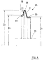
- a longitudinal section of a seal 26 can be seen in FIG. namely the seal 26, which with the counter surface 28 of the cover 17 cooperates.
- the following description of the Features of the seal 26 also apply to the further seal 26, which is assigned to the counter surface 27 of the housing 14.
- the seal 26 includes a mounting portion 36 which in is essentially annular and how in particular can be seen from Figure 2, in the inner part 21, i.e. in the second step surface 23 is arranged sunk so that its outer surface with the second step surface 23 substantially concludes.
- the diameter of the seal 26 in the area of this Area is labeled D1.
- a first wall section 37 extends outwards, i.e. of the longitudinal axis 13 away and initially essentially radially or slightly inclined and then with an arch that extends continues over the apex 38 and thus into the second wall section 39 passes.
- the largest diameter in the range of The apex 38 is labeled D2.
- the sealing lip 40 is in the depressurized state of the device held with a small gap in relation to the counter surface 28. But it can also be applied without tension.
- the seal 26 is axially flexible.
- the ring area between the first Diameter D1 and the second diameter D2 is larger than the ring area between the second diameter D2 and the third diameter D3, so that when pressurized Annulus 25 and thus the seal 26 on this one resulting Force acts, which deforms it axially and the sealing lip 40 applied to abut the counter surface 28.
- the application is pressure dependent, but corresponds to the arrangement of the sealing lip 40 on a smaller diameter not the full inflation pressure.
- Both valves 9, 30 are designed as electromagnetic valves.
- the main valve 30 has two positions. In the first Position (off) the main valve is de-energized. The connection to the pressure generator is closed. The connection to the atmosphere is opened. The annular chamber 25 is depressurized. In the In the second position (on), the valve is energized. The Connection to the free atmosphere is closed and the Air supply, i.e. the connection to the pressure generator is opened, so that the annular chamber 25 is pressurized. The essentially non-contact seals when depressurized 26 are activated and the air passes when there is a corresponding one Pressure exceeding valve 9. Is the target pressure reached, the main valve 30 closes and opens the Connection to the atmosphere.
- valve 9 is automatically closed Position transferred.
- the valve 9 is powered applied. This opens a bypass. The air goes through the annular chamber 25 to the main valve 30 and escapes through the connection to the free atmosphere provided there. is the target pressure is reached, the valve 9 is de-energized and closed with it. The given pressure is through this Valve held.
- the advantage of this system is that that the assignment to the bike is largely independent given by the design of the tractors or vehicles is. The critical screw connection between the wheel and the flange of the axle shaft is not affected. It is only a loose connection point to the axle housing or chassis is provided, which gives great constructive freedom and one modular structure with many identical parts.
Landscapes
- Engineering & Computer Science (AREA)
- Mechanical Engineering (AREA)
- Tires In General (AREA)
- Check Valves (AREA)
Applications Claiming Priority (2)
| Application Number | Priority Date | Filing Date | Title |
|---|---|---|---|
| DE10044885 | 2000-09-12 | ||
| DE10044885A DE10044885B4 (de) | 2000-09-12 | 2000-09-12 | Vorrichtung zum Befüllen oder Entlüften des Reifens eines Fahrzeuges, insbesondere eines Traktors |
Publications (2)
| Publication Number | Publication Date |
|---|---|
| EP1186451A2 true EP1186451A2 (fr) | 2002-03-13 |
| EP1186451A3 EP1186451A3 (fr) | 2003-12-17 |
Family
ID=7655809
Family Applications (1)
| Application Number | Title | Priority Date | Filing Date |
|---|---|---|---|
| EP01119104A Withdrawn EP1186451A3 (fr) | 2000-09-12 | 2001-08-08 | Dispositif pour dégonfler et/ou gonfler des pneumatiques d'un véhicule, en particulier d'un tracteur |
Country Status (5)
| Country | Link |
|---|---|
| US (1) | US6412525B1 (fr) |
| EP (1) | EP1186451A3 (fr) |
| JP (1) | JP3626439B2 (fr) |
| BR (1) | BR0103978A (fr) |
| DE (1) | DE10044885B4 (fr) |
Families Citing this family (7)
| Publication number | Priority date | Publication date | Assignee | Title |
|---|---|---|---|---|
| DE10208024B4 (de) * | 2002-02-26 | 2005-06-02 | Gkn Walterscheid Gmbh | Drehdurchführung für eine Vorrichtung zum Füllen oder Entlüften eines Reifens eines Traktorrades |
| US7413371B2 (en) * | 2004-01-20 | 2008-08-19 | Key Safety Systems, Inc. | Quick connect anchor |
| DE102007054887A1 (de) * | 2007-11-15 | 2009-06-04 | Dichtungstechnik G. Bruss Gmbh & Co. Kg | Dichtungsvorrichtung für ein Kraftfahrzeugrad |
| DE102010009750A1 (de) * | 2010-03-01 | 2011-09-01 | Herbert Heuer | Mehradriger Stromüberträger auf Fahrzeugräder |
| DE102013211216A1 (de) * | 2013-06-14 | 2014-12-18 | Bayerische Motoren Werke Aktiengesellschaft | Rad eines Kraftfahrzeugs mit einer Verkleidung des Speichen-Raumes |
| US9566832B2 (en) * | 2013-12-17 | 2017-02-14 | Hutchinson Sa | Hub adapter and central tire inflation system including same |
| US11454322B2 (en) | 2019-06-04 | 2022-09-27 | Fairfield Manufacturing Company, Inc. | Rotary pneumatic seal for a central tire inflation system |
Family Cites Families (10)
| Publication number | Priority date | Publication date | Assignee | Title |
|---|---|---|---|---|
| GB344109A (en) * | 1929-12-23 | 1931-03-05 | Richard Hurtley Daneel | Improvements in means for transmitting fluid pressure from a stationary to a rotary part, more particularly for inflating pneumatic tyres |
| DE1605743A1 (de) * | 1967-11-03 | 1971-01-28 | Knorr Bremse Gmbh | Vorrichtung zum Regeln des Reifendruckes von Kraftfahrzeugen |
| DE1907082A1 (de) * | 1969-02-13 | 1970-09-03 | Graubremse Gmbh | Reifenfuellanlage,insbesondere fuer Kraftfahrzeuge |
| US4598750A (en) * | 1984-11-16 | 1986-07-08 | Gant Lawrence A | Tire inflation/deflation system |
| US4685501A (en) * | 1986-03-06 | 1987-08-11 | Williams Donald E | Remotely controlled inflation/deflation valve system for a vehicle tire |
| US4862938A (en) * | 1986-12-18 | 1989-09-05 | Tire Inflation Systems Corp. | Vehicular tire dump valve and pressurization system |
| US4804027A (en) * | 1987-09-17 | 1989-02-14 | Eaton Corporation | Axle and wheel assembly |
| US4938272A (en) * | 1989-01-26 | 1990-07-03 | General Motors Corporation | Valve actuator for tire pressure management |
| US5313996A (en) * | 1992-03-02 | 1994-05-24 | Paul Bragg | Wheel having spoke-integrated tire inflation passageway |
| AU2760500A (en) * | 1999-04-13 | 2000-10-19 | Dana Corporation | Tire pressure management system |
-
2000
- 2000-09-12 DE DE10044885A patent/DE10044885B4/de not_active Expired - Fee Related
-
2001
- 2001-08-08 EP EP01119104A patent/EP1186451A3/fr not_active Withdrawn
- 2001-09-03 JP JP2001266094A patent/JP3626439B2/ja not_active Expired - Fee Related
- 2001-09-11 BR BR0103978-4A patent/BR0103978A/pt not_active IP Right Cessation
- 2001-09-12 US US09/950,064 patent/US6412525B1/en not_active Expired - Fee Related
Also Published As
| Publication number | Publication date |
|---|---|
| DE10044885A1 (de) | 2002-04-04 |
| US20020038675A1 (en) | 2002-04-04 |
| DE10044885B4 (de) | 2004-08-05 |
| BR0103978A (pt) | 2002-05-21 |
| US6412525B1 (en) | 2002-07-02 |
| JP2002103935A (ja) | 2002-04-09 |
| EP1186451A3 (fr) | 2003-12-17 |
| JP3626439B2 (ja) | 2005-03-09 |
Similar Documents
| Publication | Publication Date | Title |
|---|---|---|
| EP1095799B1 (fr) | Installation de réglage de la pression de pneus | |
| EP2114701B1 (fr) | Essieu et arbre d'entraînement ou de transmission pour véhicules à système central d'alimentation en pression de gonflage | |
| DE3881591T2 (de) | Luftzufuhr und -abfuhr eines rotierenden reifens. | |
| EP3341225B1 (fr) | Passage tournant d'un système de régulation de pression de pneumatique ainsi qu'ensemble comportant un tel passage tournant et moyeu monté sur un tourillon d'essieu | |
| DE60219679T2 (de) | Reifenfüll-methode mit kontinuierlichem und pulsierenden luftfluss | |
| DE10332792A1 (de) | Zentrale Reifenaufblasanlage für lenkbare Antriebsachse | |
| DE10064231A1 (de) | Reifenaufblasvorrichtung für eine Achsschenkel-Radendanordnung | |
| DE69204527T2 (de) | Steuerventil für eine Anlage zum automatischen Auffüllen und Entleeren eines Behäters, in dem ein Gas unter Druck steht, insbesondere eines Kraftfahrzeugreifens. | |
| WO2012031880A1 (fr) | Système de régulation de la pression des pneus présentant un passage tournant | |
| EP3370983B1 (fr) | Ensemble de soupape de roue et système de régulation de pression de pneumatique comprenant au moins un tel ensemble de soupape de roue | |
| DE2630511A1 (de) | Reifendruckregelanlage | |
| EP3962758B1 (fr) | Recouvrement de moyeu pour un dispositif de remplissage de pneumatique d'un véhicule | |
| DE102011017118A1 (de) | Vorrichtung zur Anpassung des Ist-Reifendrucks wenigstens eines Reifens eines Fahrzeugs an einen aktuellen Soll-Reifendruck während der Fahrt | |
| DE3528211A1 (de) | Kraftfahrzeugreifen | |
| DE10044886B4 (de) | Anordnung mit einem Rad und einer Vorrichtung zum Befüllen oder Entlüften eines Reifens eines Fahrzeugs, insbesondere Traktors | |
| EP1338443A2 (fr) | Jonction rotative pour un dispositif pour gonfler ou dégonfler un pneu d'une roue de tracteur | |
| DE10044885B4 (de) | Vorrichtung zum Befüllen oder Entlüften des Reifens eines Fahrzeuges, insbesondere eines Traktors | |
| EP3341226B1 (fr) | Agencement de valves de roue et système de régulation de la pression des pneus comportant un tel agencement de valves de roue | |
| EP1109683B1 (fr) | Unite de roue pour vehicule avec systeme de gonflage des pneumatiques | |
| DE1505734B2 (de) | Blockiergeschuetzte hydraulische bremsanlage fuer fahrzeuge | |
| EP0038978B1 (fr) | Dispositif de réglage de pression avec indicateur pour au moins deux récipients sous pression interconnectés | |
| DE3806322A1 (de) | Vorrichtung zur einstellung des reifendruckes an fahrzeugen | |
| DE102015120134A1 (de) | Reifenbefüllvorrichtung für ein Fahrzeugrad | |
| DE102021118902A1 (de) | Drehübertragungsvorrichtung zum übertragen von steuer- und/oder arbeitsdrücken zu einem fluidkanal einer welle | |
| EP1275532B1 (fr) | Valve de gonflage pour un pneumatique comprenant une chambre à air pour roulage à plat |
Legal Events
| Date | Code | Title | Description |
|---|---|---|---|
| PUAI | Public reference made under article 153(3) epc to a published international application that has entered the european phase |
Free format text: ORIGINAL CODE: 0009012 |
|
| AK | Designated contracting states |
Kind code of ref document: A2 Designated state(s): AT BE CH CY DE DK ES FI FR GB GR IE IT LI LU MC NL PT SE TR |
|
| AX | Request for extension of the european patent |
Free format text: AL;LT;LV;MK;RO;SI |
|
| PUAL | Search report despatched |
Free format text: ORIGINAL CODE: 0009013 |
|
| AK | Designated contracting states |
Kind code of ref document: A3 Designated state(s): AT BE CH CY DE DK ES FI FR GB GR IE IT LI LU MC NL PT SE TR |
|
| AX | Request for extension of the european patent |
Extension state: AL LT LV MK RO SI |
|
| STAA | Information on the status of an ep patent application or granted ep patent |
Free format text: STATUS: THE APPLICATION HAS BEEN WITHDRAWN |
|
| 17P | Request for examination filed |
Effective date: 20040617 |
|
| 18W | Application withdrawn |
Effective date: 20040712 |