EP3370983B1 - Ensemble de soupape de roue et système de régulation de pression de pneumatique comprenant au moins un tel ensemble de soupape de roue - Google Patents
Ensemble de soupape de roue et système de régulation de pression de pneumatique comprenant au moins un tel ensemble de soupape de roue Download PDFInfo
- Publication number
- EP3370983B1 EP3370983B1 EP16794239.0A EP16794239A EP3370983B1 EP 3370983 B1 EP3370983 B1 EP 3370983B1 EP 16794239 A EP16794239 A EP 16794239A EP 3370983 B1 EP3370983 B1 EP 3370983B1
- Authority
- EP
- European Patent Office
- Prior art keywords
- valve
- wheel
- tire
- control
- piston
- Prior art date
- Legal status (The legal status is an assumption and is not a legal conclusion. Google has not performed a legal analysis and makes no representation as to the accuracy of the status listed.)
- Active
Links
Images
Classifications
-
- B—PERFORMING OPERATIONS; TRANSPORTING
- B60—VEHICLES IN GENERAL
- B60C—VEHICLE TYRES; TYRE INFLATION; TYRE CHANGING; CONNECTING VALVES TO INFLATABLE ELASTIC BODIES IN GENERAL; DEVICES OR ARRANGEMENTS RELATED TO TYRES
- B60C23/00—Devices for measuring, signalling, controlling, or distributing tyre pressure or temperature, specially adapted for mounting on vehicles; Arrangement of tyre inflating devices on vehicles, e.g. of pumps or of tanks; Tyre cooling arrangements
- B60C23/001—Devices for manually or automatically controlling or distributing tyre pressure whilst the vehicle is moving
- B60C23/003—Devices for manually or automatically controlling or distributing tyre pressure whilst the vehicle is moving comprising rotational joints between vehicle-mounted pressure sources and the tyres
- B60C23/00363—Details of sealings
-
- B—PERFORMING OPERATIONS; TRANSPORTING
- B60—VEHICLES IN GENERAL
- B60C—VEHICLE TYRES; TYRE INFLATION; TYRE CHANGING; CONNECTING VALVES TO INFLATABLE ELASTIC BODIES IN GENERAL; DEVICES OR ARRANGEMENTS RELATED TO TYRES
- B60C23/00—Devices for measuring, signalling, controlling, or distributing tyre pressure or temperature, specially adapted for mounting on vehicles; Arrangement of tyre inflating devices on vehicles, e.g. of pumps or of tanks; Tyre cooling arrangements
- B60C23/001—Devices for manually or automatically controlling or distributing tyre pressure whilst the vehicle is moving
- B60C23/003—Devices for manually or automatically controlling or distributing tyre pressure whilst the vehicle is moving comprising rotational joints between vehicle-mounted pressure sources and the tyres
- B60C23/00354—Details of valves
-
- B—PERFORMING OPERATIONS; TRANSPORTING
- B60—VEHICLES IN GENERAL
- B60C—VEHICLE TYRES; TYRE INFLATION; TYRE CHANGING; CONNECTING VALVES TO INFLATABLE ELASTIC BODIES IN GENERAL; DEVICES OR ARRANGEMENTS RELATED TO TYRES
- B60C23/00—Devices for measuring, signalling, controlling, or distributing tyre pressure or temperature, specially adapted for mounting on vehicles; Arrangement of tyre inflating devices on vehicles, e.g. of pumps or of tanks; Tyre cooling arrangements
- B60C23/001—Devices for manually or automatically controlling or distributing tyre pressure whilst the vehicle is moving
- B60C23/003—Devices for manually or automatically controlling or distributing tyre pressure whilst the vehicle is moving comprising rotational joints between vehicle-mounted pressure sources and the tyres
- B60C23/00345—Details of the rotational joints
Definitions
- the invention relates to a Radventilan Aunt for a tire pressure control system of a vehicle, which Radventilan himself a pneumatically switchable wheel valve and a working principle of a pressure compensating shuttle valve as a vent valve whose control input to be connected to the tire interior tire port and its input to be connected as a control input to an air supply line, said the wheel valve arrangement comprises the further features of the preamble of claim 1. Furthermore, the invention relates to a tire pressure regulating system with such, each having an air-inflatable tire and connected to the tire pressure control system associated wheel valve assembly.
- Tire pressure control systems are used in motor vehicles, such as commercial vehicles such as trucks, tractors, tractors or earthmoving machines and also in non-driven vehicles, such as trailers to adapt to the tire pressure in the tire in different operating situations.
- a tire pressure adjustment takes place primarily depending on the surface to be traveled. Due to the tire pressure, the footprint of the tire can be changed. A tire has a larger contact patch at a lower tire pressure than at a higher tire pressure. For this reason, it is better to drive with a lower tire pressure and with a higher footprint on soft ground than on a paved road. It is also advisable to adjust the tire pressure and thus the tire inflation to the respective load condition of the vehicle.
- Tire pressure adjustment can be done while the vehicle is moving. By an optimized adjustment of the tire inner pressure, the rolling resistance and the tire wear can be significantly reduced, depending on the background. In addition, optimally set tire pressure leads to noticeably reduced fuel consumption.
- Such tire pressure control systems have a rotary feedthrough as Heilesttragungswegsamkeit between the vehicle-side facilities of the tire pressure control system and the associated wheel-side units.
- compressed air is transmitted from a vehicle-side compressed air source through the rotary feedthrough to the rotatably mounted wheel.
- a desired lowering of the tire inner pressure if no wheel-side tire ventilation is provided.
- Such a rotary feedthrough comprises a stator arranged on the vehicle side and a rotor separated by a movement gap from this and arranged on the wheel side.
- Stator and rotor are typically arranged coaxially to the axis of rotation of the wheel.
- the stator and the rotor have annular grooves or chambers, which are opposite one another with respect to the movement gap and point towards each other, and which can be activated by seals (pressure seals) which can be activated EP 1 095 799 B1 described to be sealed for the time of compressed air transmission to form a compressed air transmission chamber.
- Rad flash memory is provided to the rotor of the rotary feedthrough leading to the rim air line. This passes through the rim in an opening and opens into the tire interior.
- a controllable valve - a wheel valve - is turned on, which is opened for the process of tire pressure control and closed after completion of the process.
- the compressed air itself is typically provided in a motor vehicle with a compressor arranged on the vehicle as a compressed air source.
- a compressor is usually used in such vehicles for operating the brake system existing compressor.
- a wheel valve arrangement for a tire pressure control system according to the preamble of claim 1 is known.
- This wheel valve arrangement comprises a wheel valve connected to the air supply line supplied to the wheel by the rotary feedthrough, whose outlet is connected to the inlet of a changeover valve operating on the principle of a pressure compensator.
- the shuttle valve is designed in this prior art as a quick exhaust valve.
- the rule page the quick exhaust valve is in fluid communication with the tire interior.
- the wheel valve is switched by means of a separate compressed air actuated control line.
- a wheel valve arrangement can only be used in conjunction with a two-channel rotary feedthrough.
- a wheel valve arrangement with the features of the preamble of claim 1 is made EP 0 387 495 A1 known.
- this or its piston rod must be performed.
- the control piston must have a certain thickness and the piston rod must be guided over a corresponding length if tilting is to be avoided.
- such a guide or bearing of the control piston inertly to the required height not insignificant.
- the invention is therefore based on the object form such a way that despite the presence of a switchable Radventils as part of the Radventilanssen for driving the same and for the desired tire pressure control only a single-channel rotary feedthrough is needed, that is the Rotary transmission in those phases in which no compressed air is transmitted, can be depressurized and yet the control piston, without having to interpret this longer for the purpose of its storage, is performed without jamming.
- This wheel valve arrangement comprises a switchable wheel valve and is designed in such a way that it can be switched from its closed position into its open position with the target pressure (target pressure) present in the air supply line, with which the tire carried by the wheel is to be filled.
- target pressure target pressure
- the wheel valve already opens at the minimum air pressure provided for the tire carried by the wheel. This ensures that the wheel valve opens regardless of the range of internal tire pressure with which the tire is to be driven.
- the wheel valve opens already at a pressure which is slightly below the intended minimum tire inflation pressure.
- the minimum tire inflation pressure may be one that is dictated by a particular use of the tire. This may also be the minimum inflation pressure at which the tire can still be driven without having to suffer any damage. In this case, this is the minimum filling pressure specified by the manufacturer.
- the piston head of the control piston is relatively large compared to the diameter of the valve body.
- the fact is used that a large amount of air is provided by the vehicle-side air supply for switching the wheel valve.
- this is designed to promote 1000 liters and more in a short time.
- the control chamber of the control cylinder which is connected to the air supply line, have a relatively large cross-sectional area, without affecting the switching operation.
- the present in the air supply line pressure is also on the input side of the shuttle valve, as designed on the principle of a pressure compensating shuttle valve designed to. This pressure is regularly greater than the ambient pressure for the purposes of a valve circuit. If the wheel valve is opened by the pressure present in the air supply line, the control side of the shuttle valve is subjected to the air pressure prevailing in the tire interior. If this is greater than that in the air supply line pending, a venting of the tire via a vent opening of the shuttle valve. The shuttle valve switches in such a pressurization of its inputs in its venting position, until the quick exhaust valve closes again as a result of an adjusting pressure equilibrium. In the case of tire inflation, the pressure in the air supply line is greater than that in the tire interior.
- a quick exhaust valve has a sufficiently large vent cross section, so that a tire drain can be made in a short time.
- the Radventilan gleichstutzen is that nozzle in which otherwise a commercially available valve is screwed.
- the wheel valve forms with the preferably designed as a quick exhaust valve shuttle a unit, so that only the quick exhaust valve is connected with its input side to an air supply line.
- the control passage necessary for opening the wheel valve is directly connected to the input side of the quick exhaust valve.
- the piston head of the control piston of the wheel valve is distinct, typically several times greater than the diameter of the valve body.
- the control piston and a portion of the integrally formed piston rod identify a cylindrical guide bush, in which a stationary relative to the movement of the control piston arranged guide pin engages.
- the leadership of the piston rod in the region of the control piston is internal in such a configuration. In the radial circumferential direction of the control piston then only needs a seal with the inner wall of the control cylinder, but not necessarily causes a guide to become.
- the control piston itself is also mounted in a cylindrical passage through which engages the tire port for the purpose of its actuation of the valve body.
- the bottom of the guide bushing together with the end face of the guide pin can form a stop by which the maximum return position of the control piston is defined.
- This stop is tuned to the seal carried by the valve body, so that the stop formed by the bottom of the guide bush on the end face of the guide pin, if any, only comes into play when the desired seal is achieved between the valve body and the valve seat.
- the piston rod is typically designed as a hollow rod.
- the hollow channel of the piston rod is aligned with an introduced into the guide pin air duct, which in turn typically leads to a measuring port, where the tire inflation pressure can be detected.
- Such a design of the piston rod also allows an embodiment in which to use a measuring tube protruding into the wheel valve connecting piece. Can be connected to the piston rod and a hose whose open end for the pressure detection is located inside the tire.
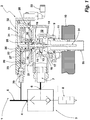
- FIG. 1 shows a schematic representation of a wheel valve arrangement 1 of a tire pressure control system, not shown in more detail.
- the wheel valve assembly 1 comprises a wheel valve 2, which is shown in a section, and a quick exhaust valve 3, which is shown with its switching symbol.
- the wheel valve 2 and the quick exhaust valve 3 form a compact assembly.
- the quick exhaust valve 3 is a working on the principle of a pressure compensating shuttle valve. Its input 4 is connected to an air supply line 5 connected.
- the control input 6 of the quick exhaust valve 3 is connected to a tire port 7 of the wheel valve 2, via the fluid Wegsamkeit between the control input 6 and the tire interior, to which the Radventilan Aunt 1 is connected, can be made.
- the quick exhaust valve 3 further comprises an exhaust outlet 8, from which in the case of a desired reduction in tire pressure, the air discharged from the tire via the tire connection channel 7 exits air into the environment.
- the air supply line 5 is connected in a manner not shown to a single-channel rotary feedthrough with activatable pressure seals.
- On the vehicle side there is a compressed air supply and a control unit for the tire control, via which pressure supply the necessary compressed air for controlling the Radventilan Aunt 1 is provided. This is transmitted from the vehicle-side compressed air supply to the wheel valve assembly 1 via the aforementioned single-channel rotary feedthrough.
- the wheel valve 2 comprises a wheel connection 9, executed with the illustrated embodiment as a Radventilan gleichstutzenamam, with which the Radventilan Aunt is connected to the fixed in a rim 10 of the tire wheel bearing Radventilan gleichstutzen 11.
- the wheel connection 9 is placed on the free end of the Radventilan gleichstutzens 11 and fixed thereto.
- the wheel valve 2 has the previously mentioned tire connection channel 7, the control input 6 of the quick exhaust duct 3 with the wheel 9 and, if this, as in FIG. 1 shown connected to a Radventilan gleichstutzen 11, connects to the tire interior.
- the tire connection channel 7 is designed as an angle piece in the illustrated embodiment.
- the valve seat 13 is directed towards the wheel connection 9 facing and is provided by a circumferential rounded edge of a cylindrical projection 14, wherein the valve seat 13 itself formed on a radially inwardly directed circumferential ridge 15 is formed.
- valve body 17 With the valve seat 13, in the closed position of the wheel valve 2, a valve body 17 cooperates, which carries a sealing disk 18 on its side facing the valve seat 13. This has a certain elasticity of material, so that the valve seat 13 can be pressed slightly into the sealing surface of the sealing disk 18 in order to bring about the desired sealing effect when the wheel valve 2 is closed.
- the valve body 17 is carried by a piston rod 19.
- the piston rod 19 is guided sealed by the ring cylinder 14 carrying the valve seat 13 with respect to the deflector chamber wall 20 opposite the wheel connection 9. Outside the deflection chamber 12, the piston rod 19 engages in a control cylinder 21 a.
- the piston rod 19 carries at its opposite end to the valve body 17, a control piston 22 which is supported in the radial direction on the outside by means of a circumferential piston seal 23 on the inner wall of the control cylinder.
- FIG. 1 shows the wheel valve 2 in its closed position, in which the valve body 17 rests against the valve seat 13.
- a helical compression spring 24 through which the sealing side of the sealing washer 18 of the valve body 17 is biased against the valve seat 13.
- the helical compression spring 24 is supported, on the one hand, on the side of the deflection chamber wall 20 facing away from the deflection chamber 12 and, on the other hand, on the side of the control piston 22 facing this wall 20.
- the control cylinder 21 is divided by the control piston 22 into two chambers, wherein one of the two chambers, namely the one which is located on the the helical compression spring 24 is located opposite side, a control chamber 28 forms.
- a control line 29 is connected to the control chamber, which in turn is connected to the air supply line 5. If the control chamber 28 is acted upon by a certain air pressure, thereby the control piston 22 and thus the piston rod 19 with the valve body 17 seated thereon moved longitudinally axially, whereby the valve body 17 is lifted from the valve seat 13 and the wheel valve 2 is opened.
- the connection of the control chamber 28 to the air supply line 5 is shown only schematically in the illustrated embodiment. Preferred is an embodiment in which the control line 29 is connected directly to a connection fitting of the quick exhaust valve 3, so that when mounting the Radventilan angel 1 only the air supply line 5 must be connected to the input of the quick exhaust valve 3.
- the diameter of the control piston 22 is as shown FIG. 1 clearly visible, by a multiple larger than the diameter of the valve body 17.
- the diameter of the control piston 22 is about 2.5 times as large as the diameter of the valve body 17.
- the relevant for an operation of the wheel valve surface of the piston head This reduction is required so that the control piston 22 even at low, located in the air supply line 5 pressure - the target pressure of the tire pressure control - can be moved to the valve body 17 from the valve seat 13 to move off to open the wheel valve 2.
- the effective area of the piston head of the control piston 22 in this respect is adapted to the opposing forces to be overcome in order to make the desired movement at the respectively requiredjanello spalldruck in the air supply line 5 can.
- the piston rod 19 is designed as a hollow rod.
- the inner channel 30 of the piston rod 19 is in fluid communication with an air channel 31, inserted into the lid 32 of the control cylinder 21.
- the air channel 31 continues in the guide pin 26 and opens at the end face and is therefore in fluid communication with the channel 30 of the piston rod 19.
- the other end of the air channel 31 is guided to a measuring port 33 to which a pressure gauge is connectable.
- a battery-operated pressure measuring sensor is located at the measuring connection 33, which wirelessly transmits its measured values to the vehicle-side control device for controlling the tire pressure regulating system.
- the pressure measuring sensor is located outside of the metal housing of the wheel valve. 2
- a measuring tube 34 In the free end of the piston rod 19 is a measuring tube 34, which may well be designed as a measuring tube used. This extends into the Radventilan gleichstutzen 11 and ends in the illustrated embodiment in this. It is understood that with a movement of the actuating piston 19 and the measuring tube 34 is moved.
- the tire internal pressure can also be measured as static air pressure during the process of tire inflation or tire wear.
- a detection of the static air pressure is also possible when the tire-side mouth of the measuring tube 34 is located within the Radventilan gleichstutzens 11, although at this point prevail at a tire pressure control particularly high flow velocities.
- the detection of the air pressure or of the changing air pressure during a tire filling or a tire evacuation allows a control of the filling or emptying process via such a pressure measuring sensor. This not only allows an exact determination of the current tire internal pressure, but also a particularly rapid tire pressure control.
- proportional valves serve the purpose of adjusting the desired tire internal pressure.
- such valves have the disadvantage that with decreasing pressure contrast between the target pressure (target pressure) and the actual pressure, the pressure compensation speed decreases. Therefore, for some applications of this type of pressure control is considered too slow. If, on the other hand, the pressure is detected via a pressure measuring probe connected to measuring port 33, the tire filling or emptying process can be ended exactly when the desired tire inflation pressure has been set. The filling or emptying process runs at maximum speed over the entire time of tire filling or tire emptying.
- the filter basket 35 is designed in the illustrated embodiment as a strainer and is used to prevent penetration of the inner wall of the tire dissolved rubber particles in the wheel valve 2 and also in the measuring tube 34 with his relatively small diameter. Through the filter basket 35 are effective such, at prevented a driving operation of the tire rubber particles to penetrate into the Radventilan gleichstutzen 11 so that the tightness of the Radventils 2 and the continuity of the measuring channel is not affected by contamination.
- An advantage of the above-described detection of the tire internal pressure with the measuring valve passing through the wheel valve is also that only a single opening in the rim of the wheel is required for these purposes.
Landscapes
- Engineering & Computer Science (AREA)
- Mechanical Engineering (AREA)
- Tires In General (AREA)
- Check Valves (AREA)
Claims (11)
- Ensemble de soupape de roue pour un système de régulation de pression de pneumatique d'un véhicule, lequel ensemble de soupape de roue (1) comporte une soupape de roue (2) commutable pneumatiquement et un sélecteur de circuit (3) faisant office de soupape de purge d'air fonctionnant selon le principe d'une balance manométrique, dont l'entrée de régulation (6) doit être raccordée à un canal de raccordement (7) au pneumatique qui mène à l'intérieur du pneumatique et dont l'entrée (4), faisant office d'entrée de commande, doit être raccordée à une conduite d'alimentation en air (5), la soupape de roue (2) commutable pneumatiquement étant intégrée au canal de raccordement (7) au pneumatique afin de couper et d'ouvrir une circulation de fluide entre le sélecteur de circuit (3) et un raccordement de roue (9) faisant partie de l'ensemble de soupape de roue (1), laquelle soupape de roue (2) présente un corps de soupape (17), mobile grâce à une tige de piston (19), lequel agit dans la position fermée au moyen d'au moins un élément à ressort (24) contre le siège de soupape (13) qui lui est affecté et qui peut être déplacé par la tige de piston (19) dans une position ouverte écarté du siège de soupape (13), et présente un piston de commande (22), raccordé à la tige de piston (19), mené dans un cylindre de commande (21), lequel cylindre de commande (21) est raccordé ou est à raccorder par son compartiment de commande (28) délimité par le côté commande du piston de commande (22), au moyen d'une conduite de commande (29), à la conduite d'alimentation en air (5) du côté d'entrée du sélecteur de circuit (3), le piston de commande (22) étant conçu de telle sorte que le corps de soupape (17) peut, afin d'ouvrir la soupape de roue (2), s'écarter de son siège de soupape (13) grâce à la pression cible de remplissage du pneumatique en attente dans la conduite d'alimentation en air (5), caractérisé en ce que la tige de piston (19) présente sur un tronçon supportant la tige de piston (22) une douille de guidage (25) centrée, dans laquelle s'engage un tourillon de guidage (26) fixe par rapport au mouvement de la tige de piston (19) afin de loger la tige de piston (19).
- Ensemble de soupape de roue selon la revendication 1, caractérisé en ce que la conduite de commande (29) est raccordée à un robinet de raccord du sélecteur de circuit (3) situé côté entrée, grâce auquel robinet de raccord, le sélecteur de circuit (3) est raccordé à la conduite d'alimentation en air (5).
- Ensemble de soupape de roue selon la revendication 1 ou 2, caractérisé en ce que le sélecteur de circuit est conformé en soupape de purge rapide (3).
- Ensemble de soupape de roue selon l'une des revendications 1 à 3, caractérisé en ce que le diamètre du fond de piston du piston de commande (22) présente une telle surface de piston que, pour l'ouverture de la soupape de roue en écartant le corps de soupape (17) de son siège de soupape (13), la soupape de roue (2) peut être écartée grâce à la pression cible de remplissage du pneumatique en attente dans la conduite d'alimentation en air (5).
- Ensemble de soupape de roue selon l'une des revendications 1 à 4, caractérisé en ce que le piston de commande (22) est conformé pour écarter le corps de soupape (17) du siège de soupape (13) à l'aide de la tige de piston (19), dès lors que la pression existant dans la conduite d'alimentation en air (5) correspond à la pression interne minimale de pneumatique qui a été définie ou qu'elle est même légèrement inférieure à cette dernière.
- Ensemble de soupape de roue selon la revendication 5, caractérisé en ce que la surface du fond de piston du piston de commande (22) correspond à un multiple de la surface du corps de soupape (17).
- Ensemble de soupape de roue selon l'une des revendications 1 à 6, caractérisé en ce que le fond de la douille de guidage (25) est conformé en butée avec la surface frontale du tourillon de guidage (26).
- Ensemble de soupape de roue selon l'une des revendications 1 à 7, caractérisé en ce que le corps de soupape (17) est solidarisé de manière rigide avec la tige de piston (19).
- Ensemble de soupape de roue selon l'une des revendications 1 à 8, caractérisé en ce que le corps de soupape (17) de la soupape de roue (2) se trouve dans un coude du canal de raccordement (9) au pneumatique, un siège de soupape (13) annulaire, orienté vers le raccordement à la roue (9) étant prévu à l'intérieur du coude, à travers lequel passe la tige de piston (19) et que le corps de soupape (17) peut s'écarter de son siège de soupape (13), grâce à un mouvement de la tige de piston (22) vers le raccordement à la roue (9).
- Ensemble de soupape de roue selon l'une des revendications 1 à 9, caractérisé en ce que la tige de piston (19) est conformée en tige creuse et que le tourillon de guidage (26) présente un canal d'air (31) en liaison de circulation de fluide avec le canal de la tige de piston (19) et relié à un raccord de mesure (33).
- Système de régulation de pression de pneumatique pour un véhicule avec une source d'air comprimée disposée du côté véhicule, comportant un passage tournant affecté à chaque roue raccordée au système de régulation de pression de pneumatique destiné à transférer de l'air comprimé à la roue supportant le pneumatique, comportant un dispositif de commande pour piloter le processus d'augmentation et/ou de baisse de la pression interne des pneumatiques raccordés au système de régulation de pression de pneumatique et comportant un ensemble de soupape de roue (1) selon l'une des revendications 1 à 10 affecté à chaque roue raccordée au système de régulation de pression de pneumatique.
Applications Claiming Priority (2)
| Application Number | Priority Date | Filing Date | Title |
|---|---|---|---|
| DE202015105859.4U DE202015105859U1 (de) | 2015-11-04 | 2015-11-04 | Radventilanordnung sowie Reifendruckregelanlage mit wenigstens einer solchen Radventilanordnung |
| PCT/EP2016/076327 WO2017076849A1 (fr) | 2015-11-04 | 2016-11-02 | Ensemble de soupape de roue et système de régulation de pression de pneumatique comprenant au moins un tel ensemble de soupape de roue |
Publications (2)
| Publication Number | Publication Date |
|---|---|
| EP3370983A1 EP3370983A1 (fr) | 2018-09-12 |
| EP3370983B1 true EP3370983B1 (fr) | 2019-05-15 |
Family
ID=57281195
Family Applications (1)
| Application Number | Title | Priority Date | Filing Date |
|---|---|---|---|
| EP16794239.0A Active EP3370983B1 (fr) | 2015-11-04 | 2016-11-02 | Ensemble de soupape de roue et système de régulation de pression de pneumatique comprenant au moins un tel ensemble de soupape de roue |
Country Status (4)
| Country | Link |
|---|---|
| US (1) | US10661612B2 (fr) |
| EP (1) | EP3370983B1 (fr) |
| DE (1) | DE202015105859U1 (fr) |
| WO (1) | WO2017076849A1 (fr) |
Families Citing this family (8)
| Publication number | Priority date | Publication date | Assignee | Title |
|---|---|---|---|---|
| EP3402684B1 (fr) * | 2016-01-13 | 2019-12-04 | Dana Heavy Vehicle Systems Group, LLC | Ensemble valve pour un système de gestion de pression de pneumatique |
| RU2681137C2 (ru) * | 2017-04-26 | 2019-03-04 | Сергей Владимирович Бриндюк | Способ выращивания посевных сельскохозяйственных культур (варианты) |
| FR3068299B1 (fr) * | 2017-06-30 | 2019-08-16 | Poclain Hydraulics Industrie | Pivot de direction ameliore formant un conduit pneumatique interne |
| DE102019112320B4 (de) | 2019-05-10 | 2026-04-23 | Illinois Tool Works Inc. | Drehübertragunsvorrichtung zum übertragen von steuer- und/oder arbeitsdrücken zu einem zumindest bereichsweise im inneren einer welle aufgenommenen oder ausgebildeten fluidkanal |
| TW202100379A (zh) * | 2019-06-27 | 2021-01-01 | 王士榮 | 胎壓控制裝置 |
| US11117426B1 (en) | 2021-03-24 | 2021-09-14 | Ptg Reifendruckregelsysteme Gmbh | Rotary transmission leadthrough as part of a tire pressure control system |
| US12528318B2 (en) | 2022-05-27 | 2026-01-20 | Deere & Company | Compact rotary union assembly for a wheel hub |
| DE102024209969A1 (de) * | 2024-10-15 | 2026-04-16 | Zf Cv Systems Global Gmbh | Pneumatisches Radventil |
Family Cites Families (39)
| Publication number | Priority date | Publication date | Assignee | Title |
|---|---|---|---|---|
| US1865231A (en) | 1929-05-06 | 1932-06-28 | Russell E Buck | Tire valve stem |
| GB344109A (en) | 1929-12-23 | 1931-03-05 | Richard Hurtley Daneel | Improvements in means for transmitting fluid pressure from a stationary to a rotary part, more particularly for inflating pneumatic tyres |
| US1969225A (en) | 1931-06-10 | 1934-08-07 | Sterling Automotive Products C | Tire valve |
| US2361890A (en) | 1936-09-30 | 1944-10-31 | Jenkins Bros | Valve stem |
| US2095912A (en) | 1937-02-27 | 1937-10-12 | Boyd Andrew Jackson | Inflating valve |
| US2128623A (en) | 1937-07-27 | 1938-08-30 | William P Stuck | Valve |
| US2418730A (en) | 1944-01-13 | 1947-04-08 | Schule Georges Charles | Device for supplying air to vehicle tires |
| DE827605C (de) | 1950-04-15 | 1952-01-10 | Erwin Krauskopf | Anordnung an mit Luftreifen versehenen Fahrzeugraedern |
| US2854020A (en) | 1956-06-28 | 1958-09-30 | Scovill Manufacturing Co | Tire valve inflation cap or extension |
| US3180349A (en) | 1961-10-25 | 1965-04-27 | Bridgeport Brass Co | Tubeless tire valve |
| US4072048A (en) | 1976-04-01 | 1978-02-07 | John Arvan | Indicating apparatus for measuring the pressure of a fluid within a container |
| US4739813A (en) | 1984-04-17 | 1988-04-26 | Bridge Products, Inc. | Tubeless tire valve |
| DE8516229U1 (de) | 1985-06-03 | 1986-10-09 | Alligator Ventilfabrik GmbH, 7928 Giengen | Ventil für Fahrzeugreifen |
| IT209132Z2 (it) | 1986-03-04 | 1988-09-12 | Bridgeport Brass Spa | Perfezionamenti a valvole per pneumatici di tipo tubeless. |
| EP0378891B1 (fr) * | 1988-01-11 | 1993-06-16 | Eaton Corporation | Dispositif de dégonflement rapide de pneumatiques |
| DE3908807A1 (de) * | 1989-03-17 | 1990-09-20 | Wabco Westinghouse Fahrzeug | Einrichtung zur aenderung des druckes im reifen eines fahrzeuges |
| US5309969A (en) * | 1991-12-17 | 1994-05-10 | Chander Mittal | Apparatus for repeatable adjustment of tire pressure |
| US5816284A (en) | 1996-08-28 | 1998-10-06 | Lin; Nan-Cheng | Tire valve extension attachment |
| SE512806C2 (sv) | 1998-09-11 | 2000-05-15 | Innovationssupport Ab | Svivelkoppling för reglering av lufttryck i fordonsdäck |
| US6250327B1 (en) * | 1999-02-25 | 2001-06-26 | Dana Corporation | Fluid flow valve with variable flow rate |
| US6363985B1 (en) | 2000-04-18 | 2002-04-02 | Spice Technology, Inc. | Rotary air coupling for tire inflation system |
| DE19950191C1 (de) | 1999-10-19 | 2001-05-10 | Tigges & Winckel Bonumwerke | Reifendruckregelanlage |
| EP1182061A3 (fr) | 2000-08-22 | 2003-01-22 | Alligator Ventilfabrik GmbH | Valve de gonflage pour la jante d'un pneumatique pour un véhicule |
| DE10044886B4 (de) | 2000-09-12 | 2006-03-16 | Gkn Walterscheid Gmbh | Anordnung mit einem Rad und einer Vorrichtung zum Befüllen oder Entlüften eines Reifens eines Fahrzeugs, insbesondere Traktors |
| DE10125991A1 (de) | 2001-05-29 | 2002-12-05 | Tries Gmbh & Co Kg | Drehdurchführung für Fuidsysteme |
| US6892999B2 (en) | 2001-11-15 | 2005-05-17 | Checkfluid Inc. | Probe activated valve system |
| FR2836656B1 (fr) | 2002-03-01 | 2004-05-28 | Michelin Soc Tech | Dispositif et procede de traitement des phenomenes de perte de pression et de roulage a plat des pneumatiques d'un vehicule |
| US20050028865A1 (en) | 2003-08-05 | 2005-02-10 | Ilya Nikolayev | Rapid access tire valve for a pneumatic tire on a rim of a vehicle and connector therefor |
| DE102005018584A1 (de) | 2005-04-21 | 2006-10-26 | Deere & Company, Moline | Vorrichtung, insbesondere Drehdurchführung |
| US8191575B2 (en) | 2008-04-11 | 2012-06-05 | International Business Machines Corporation | Double poppet quick connect |
| WO2010036870A1 (fr) * | 2008-09-26 | 2010-04-01 | Hendrickson Usa, L.L.C. | Système de gonflement de bandage pneumatique à pompe parallèle |
| US7931061B2 (en) | 2008-12-15 | 2011-04-26 | Arvinmeritor Technology, Llc | Tire inflation system with integrated wheel seal |
| US20130343931A1 (en) * | 2009-09-25 | 2013-12-26 | Hendrickson Usa, L.L.C. | Tire inflation system with parallel pump |
| DE202010000254U1 (de) | 2010-02-24 | 2010-04-22 | Ptg Reifendruckregelsysteme Gmbh | Reifenventil |
| DE202010008453U1 (de) | 2010-09-06 | 2010-11-04 | Ptg Reifendruckregelsysteme Gmbh | Reifendruckregelanlage für ein Kraftfahrzeug sowie Drehdurchführung |
| DE202011051737U1 (de) | 2011-10-24 | 2011-11-04 | Ptg Reifendruckregelsysteme Gmbh | Drehdurchführung als Teil einer Reifendruckregelanlage eines Fahrzeuges |
| FR2999266A1 (fr) * | 2012-12-10 | 2014-06-13 | Daniel Duplessy | Valve multifonction principalement destinee a la regulation de la pression dans les pneumatiques de camion en fonction de la charge utile embarquee et de l'etat de la route |
| DE202013105026U1 (de) | 2013-11-08 | 2014-01-29 | Ptg Reifendruckregelsysteme Gmbh | Reifendruckregelanlage für ein Fahrzeug |
| US9248707B2 (en) | 2013-12-25 | 2016-02-02 | Joe Huayue Zhou | Intelligent tire inflation and deflation system apparatus |
-
2015
- 2015-11-04 DE DE202015105859.4U patent/DE202015105859U1/de not_active Expired - Lifetime
-
2016
- 2016-11-02 US US15/773,493 patent/US10661612B2/en active Active
- 2016-11-02 WO PCT/EP2016/076327 patent/WO2017076849A1/fr not_active Ceased
- 2016-11-02 EP EP16794239.0A patent/EP3370983B1/fr active Active
Non-Patent Citations (1)
| Title |
|---|
| None * |
Also Published As
| Publication number | Publication date |
|---|---|
| US10661612B2 (en) | 2020-05-26 |
| WO2017076849A1 (fr) | 2017-05-11 |
| US20180312019A1 (en) | 2018-11-01 |
| WO2017076849A8 (fr) | 2017-09-28 |
| EP3370983A1 (fr) | 2018-09-12 |
| DE202015105859U1 (de) | 2017-02-07 |
Similar Documents
| Publication | Publication Date | Title |
|---|---|---|
| EP3370983B1 (fr) | Ensemble de soupape de roue et système de régulation de pression de pneumatique comprenant au moins un tel ensemble de soupape de roue | |
| DE3881591T2 (de) | Luftzufuhr und -abfuhr eines rotierenden reifens. | |
| DE60013003T2 (de) | Ventil mit variabler Durchflussrate | |
| EP2613950B1 (fr) | Système de régulation de la pression des pneus présentant un passage tournant | |
| EP3556620B1 (fr) | Soupape de commande d'une installation à air comprimé | |
| DE102011017118B4 (de) | Vorrichtung zur Anpassung des Ist-Reifendrucks wenigstens eines Reifens eines Fahrzeugs an einen aktuellen Soll-Reifendruck während der Fahrt | |
| EP2426021B1 (fr) | Soupape de stationnement pour une remorque de véhicule utilitaire | |
| EP3341225B1 (fr) | Passage tournant d'un système de régulation de pression de pneumatique ainsi qu'ensemble comportant un tel passage tournant et moyeu monté sur un tourillon d'essieu | |
| EP2117854B2 (fr) | Dispositif soupape de commande pneumatique pour véhicules à suspension pneumatique, à retour mécanique de l'élément de commande | |
| EP2393680B1 (fr) | Vanne de regulation du niveau avec disque de vanne sous pression | |
| EP2396181A2 (fr) | Dispositif destiné à régler la pression du gaz dans un pneumatique du véhicule automobile | |
| EP2539163A1 (fr) | Valve de pneumatique | |
| EP3341226B1 (fr) | Agencement de valves de roue et système de régulation de la pression des pneus comportant un tel agencement de valves de roue | |
| WO2018050400A1 (fr) | Soupape de régulation de pression pour un système de traitement d'air d'un véhicule utilitaire | |
| EP4375092B1 (fr) | Ensemble valve de pression de pneu et groupe comprenant des ensembles valve de pression de pneu | |
| DE1121943B (de) | Fahrzeug-Aufhaengevorrichtung mit einer zwischen einen Fahrzeugteil und einen Achsenteil geschalteten Gasfeder und Ventileinrichtungen | |
| EP0188707A1 (fr) | Soupape de régulation de niveau avec limitation de la hauteur | |
| DE102006021712B4 (de) | Reifenfüllvorrichtung | |
| DE971748C (de) | Steuerventil fuer Druckluft-Bremsanlagen in Kraftfahrzeugen oder Kraftfahrzeuganhaengern | |
| EP1488941B1 (fr) | Moyeu coaxial étanche a l'air pour la régulation de la pression interne des pneus, même lorsque le véhicule est en marche | |
| DE2141087A1 (de) | Einstellvorrichtung fuer den luftdruck in reifen von kraftfahrzeugen | |
| DE765717C (de) | Steuerventil fuer Anhaenger-Druckmittelbremsen, insbesondere fuer Einkammer-Anhaengerbremsen | |
| DE2318535A1 (de) | Luftfederungsventil fuer fahrzeuge, insbesondere fuer container-fahrzeuge | |
| DE3407660A1 (de) | Streckbremseinrichtung, insbesondere fuer kraftfahrzeuge | |
| EP1186451A2 (fr) | Dispositif pour dégonfler et/ou gonfler des pneumatiques d'un véhicule, en particulier d'un tracteur |
Legal Events
| Date | Code | Title | Description |
|---|---|---|---|
| STAA | Information on the status of an ep patent application or granted ep patent |
Free format text: STATUS: UNKNOWN |
|
| STAA | Information on the status of an ep patent application or granted ep patent |
Free format text: STATUS: THE INTERNATIONAL PUBLICATION HAS BEEN MADE |
|
| PUAI | Public reference made under article 153(3) epc to a published international application that has entered the european phase |
Free format text: ORIGINAL CODE: 0009012 |
|
| STAA | Information on the status of an ep patent application or granted ep patent |
Free format text: STATUS: REQUEST FOR EXAMINATION WAS MADE |
|
| 17P | Request for examination filed |
Effective date: 20180413 |
|
| AK | Designated contracting states |
Kind code of ref document: A1 Designated state(s): AL AT BE BG CH CY CZ DE DK EE ES FI FR GB GR HR HU IE IS IT LI LT LU LV MC MK MT NL NO PL PT RO RS SE SI SK SM TR |
|
| AX | Request for extension of the european patent |
Extension state: BA ME |
|
| GRAP | Despatch of communication of intention to grant a patent |
Free format text: ORIGINAL CODE: EPIDOSNIGR1 |
|
| STAA | Information on the status of an ep patent application or granted ep patent |
Free format text: STATUS: GRANT OF PATENT IS INTENDED |
|
| DAX | Request for extension of the european patent (deleted) | ||
| INTG | Intention to grant announced |
Effective date: 20181214 |
|
| DAV | Request for validation of the european patent (deleted) | ||
| GRAS | Grant fee paid |
Free format text: ORIGINAL CODE: EPIDOSNIGR3 |
|
| GRAA | (expected) grant |
Free format text: ORIGINAL CODE: 0009210 |
|
| STAA | Information on the status of an ep patent application or granted ep patent |
Free format text: STATUS: THE PATENT HAS BEEN GRANTED |
|
| AK | Designated contracting states |
Kind code of ref document: B1 Designated state(s): AL AT BE BG CH CY CZ DE DK EE ES FI FR GB GR HR HU IE IS IT LI LT LU LV MC MK MT NL NO PL PT RO RS SE SI SK SM TR |
|
| REG | Reference to a national code |
Ref country code: CH Ref legal event code: EP |
|
| REG | Reference to a national code |
Ref country code: DE Ref legal event code: R096 Ref document number: 502016004739 Country of ref document: DE |
|
| REG | Reference to a national code |
Ref country code: IE Ref legal event code: FG4D Free format text: LANGUAGE OF EP DOCUMENT: GERMAN |
|
| REG | Reference to a national code |
Ref country code: NL Ref legal event code: MP Effective date: 20190515 |
|
| REG | Reference to a national code |
Ref country code: LT Ref legal event code: MG4D |
|
| PG25 | Lapsed in a contracting state [announced via postgrant information from national office to epo] |
Ref country code: SE Free format text: LAPSE BECAUSE OF FAILURE TO SUBMIT A TRANSLATION OF THE DESCRIPTION OR TO PAY THE FEE WITHIN THE PRESCRIBED TIME-LIMIT Effective date: 20190515 Ref country code: PT Free format text: LAPSE BECAUSE OF FAILURE TO SUBMIT A TRANSLATION OF THE DESCRIPTION OR TO PAY THE FEE WITHIN THE PRESCRIBED TIME-LIMIT Effective date: 20190915 Ref country code: AL Free format text: LAPSE BECAUSE OF FAILURE TO SUBMIT A TRANSLATION OF THE DESCRIPTION OR TO PAY THE FEE WITHIN THE PRESCRIBED TIME-LIMIT Effective date: 20190515 Ref country code: FI Free format text: LAPSE BECAUSE OF FAILURE TO SUBMIT A TRANSLATION OF THE DESCRIPTION OR TO PAY THE FEE WITHIN THE PRESCRIBED TIME-LIMIT Effective date: 20190515 Ref country code: LT Free format text: LAPSE BECAUSE OF FAILURE TO SUBMIT A TRANSLATION OF THE DESCRIPTION OR TO PAY THE FEE WITHIN THE PRESCRIBED TIME-LIMIT Effective date: 20190515 Ref country code: NO Free format text: LAPSE BECAUSE OF FAILURE TO SUBMIT A TRANSLATION OF THE DESCRIPTION OR TO PAY THE FEE WITHIN THE PRESCRIBED TIME-LIMIT Effective date: 20190815 Ref country code: HR Free format text: LAPSE BECAUSE OF FAILURE TO SUBMIT A TRANSLATION OF THE DESCRIPTION OR TO PAY THE FEE WITHIN THE PRESCRIBED TIME-LIMIT Effective date: 20190515 Ref country code: NL Free format text: LAPSE BECAUSE OF FAILURE TO SUBMIT A TRANSLATION OF THE DESCRIPTION OR TO PAY THE FEE WITHIN THE PRESCRIBED TIME-LIMIT Effective date: 20190515 Ref country code: ES Free format text: LAPSE BECAUSE OF FAILURE TO SUBMIT A TRANSLATION OF THE DESCRIPTION OR TO PAY THE FEE WITHIN THE PRESCRIBED TIME-LIMIT Effective date: 20190515 |
|
| PG25 | Lapsed in a contracting state [announced via postgrant information from national office to epo] |
Ref country code: LV Free format text: LAPSE BECAUSE OF FAILURE TO SUBMIT A TRANSLATION OF THE DESCRIPTION OR TO PAY THE FEE WITHIN THE PRESCRIBED TIME-LIMIT Effective date: 20190515 Ref country code: RS Free format text: LAPSE BECAUSE OF FAILURE TO SUBMIT A TRANSLATION OF THE DESCRIPTION OR TO PAY THE FEE WITHIN THE PRESCRIBED TIME-LIMIT Effective date: 20190515 Ref country code: BG Free format text: LAPSE BECAUSE OF FAILURE TO SUBMIT A TRANSLATION OF THE DESCRIPTION OR TO PAY THE FEE WITHIN THE PRESCRIBED TIME-LIMIT Effective date: 20190815 Ref country code: GR Free format text: LAPSE BECAUSE OF FAILURE TO SUBMIT A TRANSLATION OF THE DESCRIPTION OR TO PAY THE FEE WITHIN THE PRESCRIBED TIME-LIMIT Effective date: 20190816 |
|
| PG25 | Lapsed in a contracting state [announced via postgrant information from national office to epo] |
Ref country code: CZ Free format text: LAPSE BECAUSE OF FAILURE TO SUBMIT A TRANSLATION OF THE DESCRIPTION OR TO PAY THE FEE WITHIN THE PRESCRIBED TIME-LIMIT Effective date: 20190515 Ref country code: DK Free format text: LAPSE BECAUSE OF FAILURE TO SUBMIT A TRANSLATION OF THE DESCRIPTION OR TO PAY THE FEE WITHIN THE PRESCRIBED TIME-LIMIT Effective date: 20190515 Ref country code: EE Free format text: LAPSE BECAUSE OF FAILURE TO SUBMIT A TRANSLATION OF THE DESCRIPTION OR TO PAY THE FEE WITHIN THE PRESCRIBED TIME-LIMIT Effective date: 20190515 Ref country code: SK Free format text: LAPSE BECAUSE OF FAILURE TO SUBMIT A TRANSLATION OF THE DESCRIPTION OR TO PAY THE FEE WITHIN THE PRESCRIBED TIME-LIMIT Effective date: 20190515 |
|
| REG | Reference to a national code |
Ref country code: DE Ref legal event code: R097 Ref document number: 502016004739 Country of ref document: DE |
|
| PG25 | Lapsed in a contracting state [announced via postgrant information from national office to epo] |
Ref country code: IT Free format text: LAPSE BECAUSE OF FAILURE TO SUBMIT A TRANSLATION OF THE DESCRIPTION OR TO PAY THE FEE WITHIN THE PRESCRIBED TIME-LIMIT Effective date: 20190515 Ref country code: SM Free format text: LAPSE BECAUSE OF FAILURE TO SUBMIT A TRANSLATION OF THE DESCRIPTION OR TO PAY THE FEE WITHIN THE PRESCRIBED TIME-LIMIT Effective date: 20190515 |
|
| PLBE | No opposition filed within time limit |
Free format text: ORIGINAL CODE: 0009261 |
|
| STAA | Information on the status of an ep patent application or granted ep patent |
Free format text: STATUS: NO OPPOSITION FILED WITHIN TIME LIMIT |
|
| PG25 | Lapsed in a contracting state [announced via postgrant information from national office to epo] |
Ref country code: TR Free format text: LAPSE BECAUSE OF FAILURE TO SUBMIT A TRANSLATION OF THE DESCRIPTION OR TO PAY THE FEE WITHIN THE PRESCRIBED TIME-LIMIT Effective date: 20190515 |
|
| 26N | No opposition filed |
Effective date: 20200218 |
|
| PG25 | Lapsed in a contracting state [announced via postgrant information from national office to epo] |
Ref country code: PL Free format text: LAPSE BECAUSE OF FAILURE TO SUBMIT A TRANSLATION OF THE DESCRIPTION OR TO PAY THE FEE WITHIN THE PRESCRIBED TIME-LIMIT Effective date: 20190515 |
|
| REG | Reference to a national code |
Ref country code: CH Ref legal event code: PL |
|
| PG25 | Lapsed in a contracting state [announced via postgrant information from national office to epo] |
Ref country code: CH Free format text: LAPSE BECAUSE OF NON-PAYMENT OF DUE FEES Effective date: 20191130 Ref country code: LU Free format text: LAPSE BECAUSE OF NON-PAYMENT OF DUE FEES Effective date: 20191102 Ref country code: LI Free format text: LAPSE BECAUSE OF NON-PAYMENT OF DUE FEES Effective date: 20191130 Ref country code: MC Free format text: LAPSE BECAUSE OF FAILURE TO SUBMIT A TRANSLATION OF THE DESCRIPTION OR TO PAY THE FEE WITHIN THE PRESCRIBED TIME-LIMIT Effective date: 20190515 |
|
| REG | Reference to a national code |
Ref country code: BE Ref legal event code: MM Effective date: 20191130 |
|
| PG25 | Lapsed in a contracting state [announced via postgrant information from national office to epo] |
Ref country code: FR Free format text: LAPSE BECAUSE OF NON-PAYMENT OF DUE FEES Effective date: 20191130 Ref country code: IE Free format text: LAPSE BECAUSE OF NON-PAYMENT OF DUE FEES Effective date: 20191102 |
|
| PG25 | Lapsed in a contracting state [announced via postgrant information from national office to epo] |
Ref country code: BE Free format text: LAPSE BECAUSE OF NON-PAYMENT OF DUE FEES Effective date: 20191130 |
|
| PG25 | Lapsed in a contracting state [announced via postgrant information from national office to epo] |
Ref country code: RO Free format text: LAPSE BECAUSE OF FAILURE TO SUBMIT A TRANSLATION OF THE DESCRIPTION OR TO PAY THE FEE WITHIN THE PRESCRIBED TIME-LIMIT Effective date: 20190515 |
|
| PG25 | Lapsed in a contracting state [announced via postgrant information from national office to epo] |
Ref country code: CY Free format text: LAPSE BECAUSE OF FAILURE TO SUBMIT A TRANSLATION OF THE DESCRIPTION OR TO PAY THE FEE WITHIN THE PRESCRIBED TIME-LIMIT Effective date: 20190515 |
|
| PG25 | Lapsed in a contracting state [announced via postgrant information from national office to epo] |
Ref country code: IS Free format text: LAPSE BECAUSE OF FAILURE TO SUBMIT A TRANSLATION OF THE DESCRIPTION OR TO PAY THE FEE WITHIN THE PRESCRIBED TIME-LIMIT Effective date: 20190915 |
|
| GBPC | Gb: european patent ceased through non-payment of renewal fee |
Effective date: 20201102 |
|
| PG25 | Lapsed in a contracting state [announced via postgrant information from national office to epo] |
Ref country code: HU Free format text: LAPSE BECAUSE OF FAILURE TO SUBMIT A TRANSLATION OF THE DESCRIPTION OR TO PAY THE FEE WITHIN THE PRESCRIBED TIME-LIMIT; INVALID AB INITIO Effective date: 20161102 Ref country code: MT Free format text: LAPSE BECAUSE OF FAILURE TO SUBMIT A TRANSLATION OF THE DESCRIPTION OR TO PAY THE FEE WITHIN THE PRESCRIBED TIME-LIMIT Effective date: 20190515 |
|
| PG25 | Lapsed in a contracting state [announced via postgrant information from national office to epo] |
Ref country code: SI Free format text: LAPSE BECAUSE OF FAILURE TO SUBMIT A TRANSLATION OF THE DESCRIPTION OR TO PAY THE FEE WITHIN THE PRESCRIBED TIME-LIMIT Effective date: 20190515 |
|
| PG25 | Lapsed in a contracting state [announced via postgrant information from national office to epo] |
Ref country code: GB Free format text: LAPSE BECAUSE OF NON-PAYMENT OF DUE FEES Effective date: 20201102 |
|
| REG | Reference to a national code |
Ref country code: DE Ref legal event code: R082 Ref document number: 502016004739 Country of ref document: DE Representative=s name: HAVERKAMP PATENTANWAELTE PARTG MBB, DE |
|
| PG25 | Lapsed in a contracting state [announced via postgrant information from national office to epo] |
Ref country code: MK Free format text: LAPSE BECAUSE OF FAILURE TO SUBMIT A TRANSLATION OF THE DESCRIPTION OR TO PAY THE FEE WITHIN THE PRESCRIBED TIME-LIMIT Effective date: 20190515 |
|
| P01 | Opt-out of the competence of the unified patent court (upc) registered |
Effective date: 20230529 |
|
| PGFP | Annual fee paid to national office [announced via postgrant information from national office to epo] |
Ref country code: AT Payment date: 20241018 Year of fee payment: 9 |
|
| PGFP | Annual fee paid to national office [announced via postgrant information from national office to epo] |
Ref country code: DE Payment date: 20251007 Year of fee payment: 10 |