EP1186550A2 - Siegelgerät - Google Patents
Siegelgerät Download PDFInfo
- Publication number
- EP1186550A2 EP1186550A2 EP01307354A EP01307354A EP1186550A2 EP 1186550 A2 EP1186550 A2 EP 1186550A2 EP 01307354 A EP01307354 A EP 01307354A EP 01307354 A EP01307354 A EP 01307354A EP 1186550 A2 EP1186550 A2 EP 1186550A2
- Authority
- EP
- European Patent Office
- Prior art keywords
- socket
- unit
- connecting means
- side wall
- sealing
- Prior art date
- Legal status (The legal status is an assumption and is not a legal conclusion. Google has not performed a legal analysis and makes no representation as to the accuracy of the status listed.)
- Withdrawn
Links
- 238000007789 sealing Methods 0.000 title claims abstract description 101
- 238000003780 insertion Methods 0.000 claims abstract description 35
- 230000037431 insertion Effects 0.000 claims abstract description 35
- 239000002131 composite material Substances 0.000 claims description 2
- 230000007246 mechanism Effects 0.000 description 10
- 230000000694 effects Effects 0.000 description 2
- 230000007257 malfunction Effects 0.000 description 2
- 229920003002 synthetic resin Polymers 0.000 description 2
- 239000000057 synthetic resin Substances 0.000 description 2
- 239000004677 Nylon Substances 0.000 description 1
- 239000004743 Polypropylene Substances 0.000 description 1
- 239000000463 material Substances 0.000 description 1
- 230000013011 mating Effects 0.000 description 1
- 238000000034 method Methods 0.000 description 1
- 238000010137 moulding (plastic) Methods 0.000 description 1
- 229920001778 nylon Polymers 0.000 description 1
- 229920000728 polyester Polymers 0.000 description 1
- -1 polypropylene Polymers 0.000 description 1
- 229920001155 polypropylene Polymers 0.000 description 1
- 238000010008 shearing Methods 0.000 description 1
Images


Classifications
-
- B—PERFORMING OPERATIONS; TRANSPORTING
- B65—CONVEYING; PACKING; STORING; HANDLING THIN OR FILAMENTARY MATERIAL
- B65C—LABELLING OR TAGGING MACHINES, APPARATUS, OR PROCESSES
- B65C9/00—Details of labelling machines or apparatus
- B65C9/26—Devices for applying labels
-
- G—PHYSICS
- G09—EDUCATION; CRYPTOGRAPHY; DISPLAY; ADVERTISING; SEALS
- G09F—DISPLAYING; ADVERTISING; SIGNS; LABELS OR NAME-PLATES; SEALS
- G09F3/00—Labels, tag tickets, or similar identification or indication means; Seals; Postage or like stamps
- G09F3/02—Forms or constructions
- G09F3/03—Forms or constructions of security seals
- G09F3/0305—Forms or constructions of security seals characterised by the type of seal used
- G09F3/037—Forms or constructions of security seals characterised by the type of seal used having tie-wrap sealing means
-
- B—PERFORMING OPERATIONS; TRANSPORTING
- B65—CONVEYING; PACKING; STORING; HANDLING THIN OR FILAMENTARY MATERIAL
- B65C—LABELLING OR TAGGING MACHINES, APPARATUS, OR PROCESSES
- B65C7/00—Affixing tags
- B65C7/003—Affixing tags using paddle-shaped plastic pins
- B65C7/005—Portable tools
-
- B—PERFORMING OPERATIONS; TRANSPORTING
- B65—CONVEYING; PACKING; STORING; HANDLING THIN OR FILAMENTARY MATERIAL
- B65D—CONTAINERS FOR STORAGE OR TRANSPORT OF ARTICLES OR MATERIALS, e.g. BAGS, BARRELS, BOTTLES, BOXES, CANS, CARTONS, CRATES, DRUMS, JARS, TANKS, HOPPERS, FORWARDING CONTAINERS; ACCESSORIES, CLOSURES, OR FITTINGS THEREFOR; PACKAGING ELEMENTS; PACKAGES
- B65D63/00—Flexible elongated elements, e.g. straps, for bundling or supporting articles
- B65D63/10—Non-metallic straps, tapes, or bands; Filamentary elements, e.g. strings, threads or wires; Joints between ends thereof
- B65D63/1018—Joints produced by application of integral securing members, e.g. buckles, wedges, tongue and slot, locking head and teeth or the like
- B65D63/1027—Joints produced by application of integral securing members, e.g. buckles, wedges, tongue and slot, locking head and teeth or the like the integral securing member being formed as a female and male locking member, e.g. locking head and locking teeth, or the like
- B65D63/1063—Joints produced by application of integral securing members, e.g. buckles, wedges, tongue and slot, locking head and teeth or the like the integral securing member being formed as a female and male locking member, e.g. locking head and locking teeth, or the like the female locking member being provided with at least one plastic barb
- B65D63/1081—Joints produced by application of integral securing members, e.g. buckles, wedges, tongue and slot, locking head and teeth or the like the integral securing member being formed as a female and male locking member, e.g. locking head and locking teeth, or the like the female locking member being provided with at least one plastic barb with barbs situated on opposite sides of, or concentrically in, the female locking member
-
- Y—GENERAL TAGGING OF NEW TECHNOLOGICAL DEVELOPMENTS; GENERAL TAGGING OF CROSS-SECTIONAL TECHNOLOGIES SPANNING OVER SEVERAL SECTIONS OF THE IPC; TECHNICAL SUBJECTS COVERED BY FORMER USPC CROSS-REFERENCE ART COLLECTIONS [XRACs] AND DIGESTS
- Y10—TECHNICAL SUBJECTS COVERED BY FORMER USPC
- Y10T—TECHNICAL SUBJECTS COVERED BY FORMER US CLASSIFICATION
- Y10T156/00—Adhesive bonding and miscellaneous chemical manufacture
- Y10T156/18—Surface bonding means and/or assembly means with handle or handgrip
-
- Y—GENERAL TAGGING OF NEW TECHNOLOGICAL DEVELOPMENTS; GENERAL TAGGING OF CROSS-SECTIONAL TECHNOLOGIES SPANNING OVER SEVERAL SECTIONS OF THE IPC; TECHNICAL SUBJECTS COVERED BY FORMER USPC CROSS-REFERENCE ART COLLECTIONS [XRACs] AND DIGESTS
- Y10—TECHNICAL SUBJECTS COVERED BY FORMER USPC
- Y10T—TECHNICAL SUBJECTS COVERED BY FORMER US CLASSIFICATION
- Y10T24/00—Buckles, buttons, clasps, etc.
- Y10T24/14—Bale and package ties, hose clamps
- Y10T24/1402—Packet holders
- Y10T24/141—Plastic bands
-
- Y—GENERAL TAGGING OF NEW TECHNOLOGICAL DEVELOPMENTS; GENERAL TAGGING OF CROSS-SECTIONAL TECHNOLOGIES SPANNING OVER SEVERAL SECTIONS OF THE IPC; TECHNICAL SUBJECTS COVERED BY FORMER USPC CROSS-REFERENCE ART COLLECTIONS [XRACs] AND DIGESTS
- Y10—TECHNICAL SUBJECTS COVERED BY FORMER USPC
- Y10T—TECHNICAL SUBJECTS COVERED BY FORMER US CLASSIFICATION
- Y10T24/00—Buckles, buttons, clasps, etc.
- Y10T24/14—Bale and package ties, hose clamps
- Y10T24/1498—Plastic band
-
- Y—GENERAL TAGGING OF NEW TECHNOLOGICAL DEVELOPMENTS; GENERAL TAGGING OF CROSS-SECTIONAL TECHNOLOGIES SPANNING OVER SEVERAL SECTIONS OF THE IPC; TECHNICAL SUBJECTS COVERED BY FORMER USPC CROSS-REFERENCE ART COLLECTIONS [XRACs] AND DIGESTS
- Y10—TECHNICAL SUBJECTS COVERED BY FORMER USPC
- Y10T—TECHNICAL SUBJECTS COVERED BY FORMER US CLASSIFICATION
- Y10T24/00—Buckles, buttons, clasps, etc.
- Y10T24/15—Bag fasteners
- Y10T24/153—Plastic band bag tie
Definitions
- the present invention relates to a sealing implement for attaching sealing tags such as brand labels, price tags, material description, instruction manual, etc. to clothes, shoes, bags, and other products, and more particularly to a sealing implement that can smoothly attach tags when it is set to a special-purpose tag attaching tool (gun) for attaching tags as specified above.
- sealing tags such as brand labels, price tags, material description, instruction manual, etc.
- sealing implements In general, various kinds of sealing implements have been used for banding together clothes, women's boots, sandals, shoes, etc. or for attaching brand labels, price tags, etc.
- the sealing implement comprises a filament section for forming a loop for attaching a tag, an insertion head part provided on one end of the filament part, and a socket part provided with an insertion hole for allowing the relevant inserting head part to pass, and provided on another end of the filament section.
- a plurality of sealing implements are temporarily fixed to two bars -arranged in parallel to one another in such a manner so as to enable the socket part to be easily removed.
- such sealing implement is produced by being integrally molded preferably with synthetic resin or the like, and in particular, the filament section is elongated so as to exhibit extremely strong resistance against pulling operation.
- a latching piece which is a hook mounted near the insertion hole, opens, and this causes the neck part of the insertion head part to be reversibly fixed in the socket part, and a loop-form label attaching condition is completed, and sealing is achieved.
- these sealing implements are loaded in a special-purpose tag attaching tool (gun), and it is used not only for banding together boots, sandals, and shoes but also primarily for fixing brand labels and tags that carry the instruction manual of a product on such goods by pulling the lever.
- gun special-purpose tag attaching tool
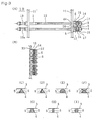
- FIG. 4 shows a perspective view of a configuration of one example of such conventional tag attaching tool (gun) 18 as shown in USP 5799375 or USP 5908110.
- an operating lever 18a as one example of an operating means.
- FIG. 4 is a perspective view showing the condition in which the sealing implement according to the present invention is set to the gun 18. A tag T is shown.
- vertical grooves 21, 22 are formed on the right and the left side of the gun for inserting the connecting bars 11, 11' of the sealing implement 10.
- the connecting bar 11 connecting the socket section 15 of the sealing implement 10 is inserted, and to the vertical groove 22, the connecting bar 11' connecting the inserting head section 13 is inserted.
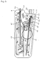
- a shooting mechanism for shooting such sealing implement as shown in Fig. 5 is provided, in that at a side portion of the vertical groove 21, a first pushing means 40 for separating each one of the socket parts 15 of the sealing implement 1 from a connecting portion of the connecting bar 11 and for pushing forward each one of the separated socket parts 15 one by one along a curved socket guide 26.
- the first pushing means 40 comprises a flexible belt 41 having a rack portion and a gear portion 42 for sliding the flexible belt 41 back and forth by mating with the rack portion.
- a tip end portion 43 of the flexible belt 41 attaches to a surface 44 of the socket part 15 which is the surface to which the filament part 12 is contacted, and then the tip end portion 43 of the flexible belt 41 separatee the socket part 15 from the connecting part of the connecting bar 11. After that it transfers the socket part 15 to a front end portion of the curved socket guide 26.
- a second pushing means 45 which separates the insertion head part 13 of the sealing implement 1 from the connecting part of the connecting bar 11' and pushes each one of the insertion head parts 13 forward to the front end portion of the curved socket guide 26, one by one.
- the second pushing means 45 comprises a tubular guide 24 fixed to a main body of the gun 18 and a piston mechanism 47 having a gripping portion for gripping the insertion head part 13 at a tip portion thereof and which slides with response to an operation of the lever 18a.
- the piston portion 47 When the piston portion 47 is slid forward, it moves towards the curved socket guide 26 by gripping the insertion head part 13 of the sealing implement 1 arranged inside of the tubular guide 24 at a tip portion thereof and inserts the insertion head part 13 into the insertion hole 14 for receiving the insertion head part 13 of the socket part 15 which has already arrived at the front end portion of the curved socket guide 26.
- the gun in order to move each one of the sealing implements 1 forming the unit of sealing implement 10 thus mounted on the gun 18, to a position to be shot out, respectively, the gun is provided with a gear mechanism 50, 50' as shown in Fig. 9, which can mate with each connection portion formed between the insertion head part 13 or the socket part 15 and the connecting bar 11 or 11', respectively.
- each gear tooth of the gear portion of the gear mechanism 50, 50' can be rotated respectively, by utilizing a suitable cam mechanism or ratchet mechanism in response to the operation of the operating means 18a, it can be designed that the connecting bar can be moved downwardly by a length corresponding to a distance formed between the adjacently arranged sealing implements.
- a contacting surface 44 which is one of the side wall surfaces of the socket part 15 of the sealing implement 10 and at which a filament part 12 is contacted, is formed with a curved surface.
- the gun has not correctly operated. This causes the sealing implement to fail to shoot or causes a part of the sealing implement to be captured inside the gun, thereby causing extra operation by removing such captured part of the sealing implement and by resetting the sealing implement each time such problems occur.
- the present invention seeks to provide a sealing implement whose mounting operation for mounting the sealing implement on a gun has operational efficiency. It also seeks to provide a sealing implement which is able to constantly maintain the correct direction of a socket part so as to avoid an occurrence of jamming.
- the present invention basically adopts a configuration described as follows. That is, the present invention relates to a sealing implement comprising a flexible filament part, an insertion head part having an appropriate engaging part provided on one end part of the filament part, and a socket part having a hole for the purpose of irreversibly inserting the insertion head part, and provided on another end of the filament.
- a unit of sealing implements comprises a plurality of single sealing implements which are mutually and adjacently arranged substantially in parallel with each other and each plurality of insertion head parts or a portion in proximity thereto and each plurality of socket parts or a portion in proximity thereto are caused to be connected to separately provided connecting bars, respectively, and further wherein side wall surfaces of the socket parts, the surfaces being adjacently arranged to each other and oppositely disposed to each other, are connected to each other via a connecting means.
- the unit of sealing implements of the present invention has the technical concept that the socket parts of the sealing implement 1 are arranged in parallel with each other on the connecting bars and are spaced apart by a predetermined distance.
- the side wall surfaces of the socket parts are connected to each other by a suitable connecting means so that an arrangement configuration of each socket part cannot be deformed and is solidly kept at a predetermined position when each one of the sealing implements is shot out by the gun.
- the directions of an arrangement of the socket parts are generally not misaligned, and when the socket part 15 is separated from the connecting bar and is inserted into an entrance portion of the curved socket guide by the pushing means, there is generally little chance that the position of the socket part would be deformed with respect to an entrance portion of the curved socket guide, thereby reducing the occurrence of jamming.
- the operational efficiency of the shooting operation of the sealing implement may be improved.
- FIG. 1 is a front view showing a configuration of one specific example of the sealing implement relating to the present invention and FIG. 2 is a side view thereof and Fig. 3 is a back side view thereof.
- a unit of sealing implements 10 comprising a plurality of single sealing implements 1 each of which comprises a flexible filament part 12, an insertion head part 13 having an appropriate engaging part 13a provided on one end part of the filament part 12 and a socket part 15 having a hole 14 for the purpose of irreversibly inserting the insertion head part 13, and provided on another end of the filament 12.
- a plurality of the single sealing implements 1 are mutually and adjacently arranged in parallel with each other and each of the plurality of insertion head parts 13 or a portion in proximity thereto and each of the plurality of socket parts 15 or a portion in proximity thereto are connected to separately provided connecting bars 11, 11', respectively.
- the sealing implement 10 according to the present invention is integrally molded generally with synthetic resin such as nylon, polypropylene, polyester, etc. as in the case of conventional sealing implements.
- FIG. 1 one specific example of the sealing implement 10 relating to the present invention is further described.
- the basic configuration of the sealing implement 10 relating to the present invention is nearly the same as that of the conventional sealing implement, and further at the socket section 15, an insertion hole 14 for irreversibly passing the inserting head section 13 is provided.
- the cross-sectional profile of the filament part 12 may be a circle, a flattened shape, or a rectangle.
- the socket section 15 is provided with an engaging section 17.
- Engaging section 17 is formed so as to project inside the insertion hole 14 from an inside surface thereof.
- Engaging section 17 is deformable and is adapted to engage with engaging section 13a which is formed on a part of the insertion head part 13 and which has a reduced diameter so as to form a stepwise configuration.
- one of the connecting bars 11 is connected to an end base portion or a portion in proximity thereto of the socket parts 15, each being arranged adjacently to each other. Additionally, a pair of the socket parts 15 which are adjacently arranged to each other are connected to each other with a suitable connecting means 5 so as to be mutually fixed.
- the side wall surfaces 3, 4 of a plurality of the socket parts 15, 15' are connected with each other by utilizing at least one connecting means 5.
- each socket part 15 is connected with the connecting bar 11 and the connecting means 5 in a lower portion and an upper portion thereof, the arrangement direction of the socket part can be prevented from being deformed even when it is shot from a gun.
- At least one connecting means 5 may be provided between a pair of side wall surfaces 3, 4 of the respective socket parts 15 of a unit of sealing implements 10.
- connecting means 5 are provided therebetween.
- one connecting means 5 is provided in the portion formed between a pair of the side wall surfaces 3, 4 of the respective socket parts 15, but it is preferred that two or three connecting means 5 are provided in the portions formed between a pair of the side wall surfaces 3, 4 of the respective socket parts 15.
- the connecting means 5 preferably has a fine configuration through out or a configuration having a portion which can attach to a side wall surface 3, 4 of the socket part 15 or attach to an opposite connecting means 5 via a pin point connection, so that it can be easily broken when a predetermined tensile strength or a predetermined shearing force is applied to the socket part 15.
- the connecting means 5 of the present invention has a suitable strength between the side wall surface 3 and 4 of the socket part 15 that enables the socket part 15 to be easily separated.
- socket parts 15 of the unit of sealing implements 10, each being adjacently arranged to each other are temporarily fixed to each other at a portion other than the connecting bar 11.
- the connecting means 5 of the present invention preferably comprises a thin and short connecting member 5' and this may be formed integrally with the socket part 15 when the socket part 15 is formed using a plastic molding method.
- the connecting member 5' forming the connecting means 5 has an uniform cross-sectional area in overall length thereof along a center axis thereof and thus it may a column or a rod having a polygonal cross-sectional configuration or the like,or it has a non-uniform cross-sectional area in overall length thereof along a center axis of the connecting member 5' as shown in Fig. 3(C) to Fig. 3(G) and Fig. 3(I).
- At least one end portion of the connecting member 5' forming the connecting means 5 may have a configuration selected from a group consisting of a circular cone type shape, a spherical shape, a semi-spherical shape, a pyramid type shape or the like as shown in Fig, 3(C) to Fig, 3(F).
- the configuration of the connecting member 5' may have a configuration which can contact the side wall surfaces 3, 4 of the socket part 15 via a pin-point connection or opposite connecting members 5' may be mutually connected to each other via a pin-point connection.
- one end of the connecting member 5' can be connected to the sidewall surface 3 or 4 of the socket part 15 via surface contact, the connecting portion of the connecting member 5' having a small cross-sectional area.
- a cross-sectional area of one end portion of the connecting member 5' of the connecting means 5,which portion contacts the side wall surface 3 of the side wall surfaces 3, 4 of a pair of the socket parts 15, is different from a cross-sectional area of another end portion of the connecting member 5' of the connecting means 5, which portion contacts the side wall surface 4 of the pair of socket parts.
- the cross-sectional area of one end portion of the connecting member 5' connected to the side wall surface is a cross-sectional area showing a connecting force that enables a pair of the socket parts 15 to be easily separated from each other when a certain external force is applied thereto.
- the connecting means 5 of the present invention may be formed by projecting the respective connecting members 5', 5' from each one of the side wall surfaces 3 and 4 of the socket parts 15 being adjacently arranged to each other, respectively : both of the tip ends contact each other at the middle portion between both side wall surfaces 3 and 4, as shown in Fig. 3(F).
- a cross-sectional configuration of the connecting member of the connecting means is a configuration selected from a group consisting of a circular type configuration, an ellipse type configuration, a rectangular type configuration, a flat type configuration, a semi-circular type configuration, a polygonal type configuration and a composite type configuration formed by combining at least two of aforementioned configurations to each other.
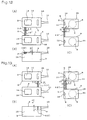
- the connecting means 5 can be formed at any portion of the side wall surface 3 or 4 of the socket part 15 but as a preferable embodiment of the present invention, as shown in Figs. 12 and 13, the connecting means 5 is provided at a position P on the side wall surface 3 or 4 of the socket part 15. Position P is located at a position communicating with or in proximity to a top surface S of the socket part 15 to which the filament part 12 is contacted and on which an insertion hole 14 into which the insertion head part 13 is inserted is provided.
- the connecting member 5' may be provided at a position formed on a side wall surface 3, 4 of the socket part 15 and located so that the distance formed between the connecting member 5' and the connecting bar 11 is set as long as possible.
- the moment for suppressing the deformation of the socket part 15 will become maximum so that the most preferable position fixing effect for the socket part 15 may be obtained.
- the connecting member 5' can also be provided at a position formed on a side wall surface 3, 4 of the socket part 15 and located so that the distance formed between the connecting member 5' and the connecting bar 11 is set as short as possible.
- the surface of goods may be prevented from being scratched by a residual connecting member 5'.
- a plurality of the connecting means 5 can be provided between a pair of the side wall surfaces 3, 4 of the respective socket parts 15 adjacently arranged to each other and oppositely disposed to each other.
- an arranging direction of the major axis of the cross-sectional configuration of one connecting member 5' is different from an arranging direction of the major axis of the cross-sectional configuration of another connecting member 5'.
- the connecting member 5'-1 which is located at a position far from the connecting bar 11, has a flat type cross-sectional configuration with a width of, for example, 0.3 mm and a thickness of, for example, 0.15mm as shown in Fig. 12(A) and Fig. 12(B).
- a width direction thereof is set in a direction in parallel with the surface direction of the upper surface S of the socket part 15. Also, as shown in Fig. 12(C), between the side wall'surfaces 3 and 4 of the respective adjacently arranged socket parts 15, one end portion 60 of the connecting member 5' which is connected to the side wall surface 3 is formed to have a configuration where its cross-sectional area gradually narrows towards the tip end portion thereof.
- the major axis of the cross-sectional configuration of the connecting member 5'-1 forming the connecting means 5, which is located at a position far from the connecting bar 11, is set at a direction which is in parallel with the surface direction of the upper surface S of the socket part 15 or with the direction of a center axis of the filament part 12.
- the connecting member 5'-2 forming the connecting means 5, which is located at a position closer to the connecting bar 11, has a flat type cross-sectional configuration with a width of, for example, 0.3 mm and a thickness of, for example, 0.15mm as shown in Fig. 13(A) and Fig. 13(B). It is arranged so that a width direction thereof is set at a direction perpendicular to the surface direction of the upper surface S of the socket part 15. Also, as shown in Fig. 13(C), between the side wall surfaces 3 and 4 of the respective adjacently arranged socket parts 15, one end portion 60 of the connecting member 5' which is connected to the side wall surface 3 is formed to have a configuration where its cross-sectional area gradually narrows towards the tip end portion thereof.
- the major axis of the cross-sectional configuration of the connecting member 5'-2 forming the connecting means 5, which is located at a position closer to the connecting bar 11, is set at a direction which is perpendicular to the surface direction of the upper surface S of the socket part 15 or perpendicular to a direction of a center axis of the filament part 12.
- an arrangement for a plurality of the socket parts 15 being adjacently arranged to each other is constantly uniform within the whole of the unit 10, and each of the socket parts 15 is so fixed to each other so as not to be deformed easily.
- each one of the sealing implements 1 can be easily separated from the connecting bar and shot out one by one, by operating an operation lever 18a provided on the gun 18, so that a tag or a label can be attached to goods.
- the unit of sealing implement of the present invention is so configured that a direction of a major axis of the cross-sectional configuration of the connecting member of the connecting means provided at a position located relatively far from the connecting bar, is arranged so as to comply with a surface direction of an upper surface of the socket part, while a direction of a major axis of the cross-sectional configuration of the connecting member of the connecting means provided at a position located relatively close to the connecting bar, is arranged so as to comply with a direction perpendicular to the surface direction of the upper surface of the socket part.
- a connecting means 5 formed into a fine string configuration 13' can also be used,as shown in Fig. 10 (A) and Fig. 10(B).
- the filament section used in the sealing implement relating to the present invention may have any kind of cross sectional configuration selected from a group consisting of a circle type, a flattened shape type, an ellipse type, a rectangular type or the like.
- the size of the socket part is preferably visually small enough to enable easy handling.
- a socket part 15 connected to the connecting bar 11 inserted into the vertical groove 21 is separated from the connecting section 58 of the connecting bar 11 by the first pushing means 40 and pushed out one by one forward along the curved socket guide 26 without jamming.
- the direction of the socket part 15 is pushed out along the socket guide 26 is turned by an angle of 90° and fits with the inserting head part 13 pushed out by a pushing pin 47 of the second pushing means 45, at the front end of the socket guide 26, through the insertion hole 14.
- the socket guide 26 changes its longitudinal direction by about 90° with a cylindrical tube so that a rod serving as the pushing means 40 is able to advance inside thereof while being bent.
- the gun is configured such that the timing of the head end of the pushing rod 41 reaching the top end of the socket guide 26 coincides with the timing of the pushing pin 47 reaching the same top end of the socket guide 26.
- the sealing implement 1 is able to attach labels successively and continuously to products, etc.
- Position Q may be approximately a center portion of the side wall surface 3, 4 of the socket part 15 and facing to a side at which the filament part 12 is existing.
- Position Q may be approximately a center portion of the side wall surface 44 of said socket part.
- Position Q may be located on a portion of or in proximity to an area at which the upper surface S of the socket part 15 on which the insertion hole 14 is provided intersects with the side wall surface 44.
- the side wall surface 44 of the socket part 15, being the side at which the filament part 12 is existing, is flat and the surface direction of the side wall surface 44 is perpendicular to the direction of the center axis of the filament part 12.
- a surface area of a region R of the socket part 15, with which a tip portion of the pushing rod 41 makes contact can be substantially enlarged and thus the operational efficiency can be greatly improved.
- a plurality of the connecting means 5 are disposed at spaces formed between two socket parts being adjacently arranged to each other.
- the present invention adopts the configuration as described above, deformation of the arrangement configuration of the socket part 15 is prevented after the sealing implement has been mounted on the gun and when each one of the socket parts 15 is pushed out by a predetermined pushing means, one by one; no jamming condition generally occurs as a result of the push direction of the top end portion of the socket part 15 being changed.
- each one of the units of sealing implements is easily taken out from its stacked stocks thereof or from a container thereof.
Landscapes
- Engineering & Computer Science (AREA)
- Computer Security & Cryptography (AREA)
- Physics & Mathematics (AREA)
- General Physics & Mathematics (AREA)
- Theoretical Computer Science (AREA)
- Mechanical Engineering (AREA)
- Labeling Devices (AREA)
- Toys (AREA)
- Coating Apparatus (AREA)
- Sealing Devices (AREA)
- Connector Housings Or Holding Contact Members (AREA)
Applications Claiming Priority (4)
| Application Number | Priority Date | Filing Date | Title |
|---|---|---|---|
| JP2000261158 | 2000-08-30 | ||
| JP2000261158 | 2000-08-30 | ||
| JP2001256165A JP2002154511A (ja) | 2000-08-30 | 2001-08-27 | 封緘具 |
| JP2001256165 | 2001-08-27 |
Publications (2)
| Publication Number | Publication Date |
|---|---|
| EP1186550A2 true EP1186550A2 (de) | 2002-03-13 |
| EP1186550A3 EP1186550A3 (de) | 2004-01-14 |
Family
ID=26598804
Family Applications (1)
| Application Number | Title | Priority Date | Filing Date |
|---|---|---|---|
| EP01307354A Withdrawn EP1186550A3 (de) | 2000-08-30 | 2001-08-30 | Siegelgerät |
Country Status (6)
| Country | Link |
|---|---|
| US (1) | US6527030B2 (de) |
| EP (1) | EP1186550A3 (de) |
| JP (1) | JP2002154511A (de) |
| KR (1) | KR20020018159A (de) |
| CN (1) | CN1341539A (de) |
| TW (1) | TW548610B (de) |
Cited By (2)
| Publication number | Priority date | Publication date | Assignee | Title |
|---|---|---|---|---|
| EP2180460A3 (de) * | 2008-10-22 | 2010-08-04 | Kabushiki-Kaisya TOSKA | Befestigungselement und Herstellungsverfahren dafür |
| WO2016196866A1 (en) * | 2015-06-04 | 2016-12-08 | Avery Dennison Retail Information Services, Llc | Plastic fastener and plastic fastener assembly |
Families Citing this family (12)
| Publication number | Priority date | Publication date | Assignee | Title |
|---|---|---|---|---|
| JP4383780B2 (ja) * | 2003-06-20 | 2009-12-16 | 有限会社エムアイティインターナショナル | ループピン結合装置 |
| USD514425S1 (en) | 2004-05-27 | 2006-02-07 | Brammall, Inc. | Locking device |
| US20060266087A1 (en) * | 2004-11-12 | 2006-11-30 | Hamilton Eric K | Locking device |
| US20100229608A1 (en) * | 2009-03-10 | 2010-09-16 | Jersey Tactical Corp. | Ratchet strap handcuff connectors |
| JP2010280410A (ja) * | 2009-06-04 | 2010-12-16 | M I T Internatl:Kk | ループピン |
| CN102476718A (zh) * | 2010-11-30 | 2012-05-30 | 鸿富锦精密工业(深圳)有限公司 | 塑料封条 |
| TR201802885T4 (tr) | 2010-12-23 | 2018-03-21 | Avery Dennison Corp | Filaman için geniş tutturma gereci. |
| US9199756B2 (en) | 2011-11-28 | 2015-12-01 | Avery Dennison Corporation | Fastener stock and device for use in dispensing plastic fasteners therefrom |
| JP2013228916A (ja) * | 2012-04-26 | 2013-11-07 | Toska Banok Co Ltd | ファスナー部材及びそのファスナー部材の装着器具 |
| US9789991B2 (en) | 2013-08-28 | 2017-10-17 | Avery Dennison Corporation | Reactor plate assembly and brush anvil for use in conjunction therewith |
| US11180267B2 (en) | 2016-12-29 | 2021-11-23 | Avery Dennison Corporation | Apparatus and method of generating a fastener and securing at least one product to at least one packaging |
| CN112258977B (zh) * | 2020-10-30 | 2025-04-25 | 保士特(东莞)塑胶制品有限公司 | 一种套环 |
Citations (2)
| Publication number | Priority date | Publication date | Assignee | Title |
|---|---|---|---|---|
| US5799375A (en) | 1995-05-17 | 1998-09-01 | J.E. Co., Ltd. | Fastener assembly |
| US5908110A (en) | 1996-10-14 | 1999-06-01 | J.E. Kabushiki Kaisha | Tag pin assembly |
Family Cites Families (9)
| Publication number | Priority date | Publication date | Assignee | Title |
|---|---|---|---|---|
| BE792298A (fr) * | 1972-05-25 | 1973-03-30 | Dennison Mfg Co | Perfectionnements aux attaches pour la reunion de deux objets ensemble |
| EP0038861B1 (de) * | 1979-11-02 | 1985-05-15 | Mitsubishi Denki Kabushiki Kaisha | Kabelbaum |
| US4790225A (en) * | 1982-11-24 | 1988-12-13 | Panduit Corp. | Dispenser of discrete cable ties provided on a continuous ribbon of cable ties |
| JPS6396021A (ja) * | 1987-07-31 | 1988-04-26 | 株式会社 トスカ | 取付部片集合体 |
| JP2613062B2 (ja) * | 1987-09-11 | 1997-05-21 | 株式会社トスカ | 連結型結束具 |
| US5967316A (en) * | 1997-10-22 | 1999-10-19 | Thomas & Betts International, Inc. | Cable tie bandoliers for use with automatic tools |
| JPH11152121A (ja) * | 1997-11-25 | 1999-06-08 | Toska Co Ltd | 封緘具集合体 |
| US6126056A (en) * | 1999-11-10 | 2000-10-03 | Kotec's Co., Ltd. | Apparatus for attaching tag pins |
| US6446311B1 (en) * | 2000-01-06 | 2002-09-10 | Kotec's Co., Ltd. | Loop pin |
-
2001
- 2001-08-27 JP JP2001256165A patent/JP2002154511A/ja active Pending
- 2001-08-29 CN CN01141104A patent/CN1341539A/zh active Pending
- 2001-08-29 TW TW090121270A patent/TW548610B/zh not_active IP Right Cessation
- 2001-08-30 EP EP01307354A patent/EP1186550A3/de not_active Withdrawn
- 2001-08-30 US US09/941,632 patent/US6527030B2/en not_active Expired - Fee Related
- 2001-08-30 KR KR1020010052937A patent/KR20020018159A/ko not_active Ceased
Patent Citations (2)
| Publication number | Priority date | Publication date | Assignee | Title |
|---|---|---|---|---|
| US5799375A (en) | 1995-05-17 | 1998-09-01 | J.E. Co., Ltd. | Fastener assembly |
| US5908110A (en) | 1996-10-14 | 1999-06-01 | J.E. Kabushiki Kaisha | Tag pin assembly |
Cited By (6)
| Publication number | Priority date | Publication date | Assignee | Title |
|---|---|---|---|---|
| EP2180460A3 (de) * | 2008-10-22 | 2010-08-04 | Kabushiki-Kaisya TOSKA | Befestigungselement und Herstellungsverfahren dafür |
| WO2016196866A1 (en) * | 2015-06-04 | 2016-12-08 | Avery Dennison Retail Information Services, Llc | Plastic fastener and plastic fastener assembly |
| US20160358518A1 (en) * | 2015-06-04 | 2016-12-08 | Avery Dennison Retail Information Services, Llc | Plastic fastener and plastic fastener assembly |
| CN107743554A (zh) * | 2015-06-04 | 2018-02-27 | 艾利丹尼森公司 | 塑料紧固件及塑料紧固件组件 |
| US10510273B2 (en) | 2015-06-04 | 2019-12-17 | Avery Dennison Corporation | Plastic fastener and plastic fastener assembly |
| CN107743554B (zh) * | 2015-06-04 | 2021-05-04 | 艾利丹尼森公司 | 塑料紧固件及塑料紧固件组件 |
Also Published As
| Publication number | Publication date |
|---|---|
| JP2002154511A (ja) | 2002-05-28 |
| US20020023724A1 (en) | 2002-02-28 |
| EP1186550A3 (de) | 2004-01-14 |
| TW548610B (en) | 2003-08-21 |
| KR20020018159A (ko) | 2002-03-07 |
| US6527030B2 (en) | 2003-03-04 |
| CN1341539A (zh) | 2002-03-27 |
Similar Documents
| Publication | Publication Date | Title |
|---|---|---|
| EP1186550A2 (de) | Siegelgerät | |
| US6371293B2 (en) | Fastener assembly | |
| NL1033810C2 (nl) | Spanbare kleminrichting, geschikt voor toepassing in bundelstrips. | |
| USRE34891E (en) | Assembly of attachments and device for attaching same | |
| US6561350B1 (en) | Sticking device | |
| US5738265A (en) | Fastener gun and fastener assembly for tag hanging | |
| CA1144322A (en) | Method and apparatus for dispensing fasteners | |
| USRE34857E (en) | Assembly of attachments and device for attaching same | |
| US6101683A (en) | Loop fastener, fastener clip including same and loop fastener dispensing tool | |
| US4538754A (en) | Fastener dispensing device | |
| JP2001354218A (ja) | ループピン結合装置 | |
| US4682721A (en) | Tag dispensing and attaching apparatus | |
| EP1489013B1 (de) | Werkzeug zum Verbinden von ringförmigen Nadeln | |
| US6009997A (en) | Loop fastener, fastener clip including same and loop fastener dispensing tool | |
| US6352156B1 (en) | Sealer | |
| JPS60217071A (ja) | 係止片取付方法及びその装置 | |
| EP1145965B1 (de) | Befestigungselement | |
| US20030164393A1 (en) | Locking element attaching device | |
| EP1378453A1 (de) | Vorrichtung zum Verbinden von ringförmigen Nadeln | |
| JP2010126176A (ja) | ループピン結合装置及びループピン打ち出し方法 | |
| EP0191183A2 (de) | Bandiermaschine | |
| KR950000370B1 (ko) | 부착물 조립체와 부착물을 부착하기 위한 장치 | |
| JP2023062696A (ja) | 一体型固定タイを自動結束工具装置に供給するための可変リザーバ装置 | |
| EP1083537A2 (de) | Siegelgerät | |
| US6065661A (en) | Automatic loop forming tag attacher apparatus and method |
Legal Events
| Date | Code | Title | Description |
|---|---|---|---|
| PUAI | Public reference made under article 153(3) epc to a published international application that has entered the european phase |
Free format text: ORIGINAL CODE: 0009012 |
|
| AK | Designated contracting states |
Kind code of ref document: A2 Designated state(s): AT BE CH CY DE DK ES FI FR GB GR IE IT LI LU MC NL PT SE TR |
|
| AX | Request for extension of the european patent |
Free format text: AL;LT;LV;MK;RO;SI |
|
| PUAL | Search report despatched |
Free format text: ORIGINAL CODE: 0009013 |
|
| AK | Designated contracting states |
Kind code of ref document: A3 Designated state(s): AT BE CH CY DE DK ES FI FR GB GR IE IT LI LU MC NL PT SE TR |
|
| AX | Request for extension of the european patent |
Extension state: AL LT LV MK RO SI |
|
| RIC1 | Information provided on ipc code assigned before grant |
Ipc: 7B 65D 63/10 B Ipc: 7G 09F 3/03 A |
|
| AKX | Designation fees paid | ||
| REG | Reference to a national code |
Ref country code: DE Ref legal event code: 8566 |
|
| STAA | Information on the status of an ep patent application or granted ep patent |
Free format text: STATUS: THE APPLICATION IS DEEMED TO BE WITHDRAWN |
|
| 18D | Application deemed to be withdrawn |
Effective date: 20040715 |