EP1186756A2 - Druckempfindliches Ventil für einen Abgasschalldämpfer und Montageverfahren dazu - Google Patents
Druckempfindliches Ventil für einen Abgasschalldämpfer und Montageverfahren dazu Download PDFInfo
- Publication number
- EP1186756A2 EP1186756A2 EP01121874A EP01121874A EP1186756A2 EP 1186756 A2 EP1186756 A2 EP 1186756A2 EP 01121874 A EP01121874 A EP 01121874A EP 01121874 A EP01121874 A EP 01121874A EP 1186756 A2 EP1186756 A2 EP 1186756A2
- Authority
- EP
- European Patent Office
- Prior art keywords
- valve
- valve plate
- wall portions
- side wall
- pivot shaft
- Prior art date
- Legal status (The legal status is an assumption and is not a legal conclusion. Google has not performed a legal analysis and makes no representation as to the accuracy of the status listed.)
- Granted
Links
Images




Classifications
-
- F—MECHANICAL ENGINEERING; LIGHTING; HEATING; WEAPONS; BLASTING
- F01—MACHINES OR ENGINES IN GENERAL; ENGINE PLANTS IN GENERAL; STEAM ENGINES
- F01N—GAS-FLOW SILENCERS OR EXHAUST APPARATUS FOR MACHINES OR ENGINES IN GENERAL; GAS-FLOW SILENCERS OR EXHAUST APPARATUS FOR INTERNAL-COMBUSTION ENGINES
- F01N1/00—Silencing apparatus characterised by method of silencing
- F01N1/16—Silencing apparatus characterised by method of silencing by using movable parts
- F01N1/166—Silencing apparatus characterised by method of silencing by using movable parts for changing the flow path through the silencer or for adjusting the dimensions of a chamber or a pipe
-
- F—MECHANICAL ENGINEERING; LIGHTING; HEATING; WEAPONS; BLASTING
- F01—MACHINES OR ENGINES IN GENERAL; ENGINE PLANTS IN GENERAL; STEAM ENGINES
- F01N—GAS-FLOW SILENCERS OR EXHAUST APPARATUS FOR MACHINES OR ENGINES IN GENERAL; GAS-FLOW SILENCERS OR EXHAUST APPARATUS FOR INTERNAL-COMBUSTION ENGINES
- F01N1/00—Silencing apparatus characterised by method of silencing
- F01N1/08—Silencing apparatus characterised by method of silencing by reducing exhaust energy by throttling or whirling
-
- F—MECHANICAL ENGINEERING; LIGHTING; HEATING; WEAPONS; BLASTING
- F01—MACHINES OR ENGINES IN GENERAL; ENGINE PLANTS IN GENERAL; STEAM ENGINES
- F01N—GAS-FLOW SILENCERS OR EXHAUST APPARATUS FOR MACHINES OR ENGINES IN GENERAL; GAS-FLOW SILENCERS OR EXHAUST APPARATUS FOR INTERNAL-COMBUSTION ENGINES
- F01N1/00—Silencing apparatus characterised by method of silencing
- F01N1/08—Silencing apparatus characterised by method of silencing by reducing exhaust energy by throttling or whirling
- F01N1/084—Silencing apparatus characterised by method of silencing by reducing exhaust energy by throttling or whirling the exhaust gases flowing through the silencer two or more times longitudinally in opposite directions, e.g. using parallel or concentric tubes
-
- F—MECHANICAL ENGINEERING; LIGHTING; HEATING; WEAPONS; BLASTING
- F01—MACHINES OR ENGINES IN GENERAL; ENGINE PLANTS IN GENERAL; STEAM ENGINES
- F01N—GAS-FLOW SILENCERS OR EXHAUST APPARATUS FOR MACHINES OR ENGINES IN GENERAL; GAS-FLOW SILENCERS OR EXHAUST APPARATUS FOR INTERNAL-COMBUSTION ENGINES
- F01N1/00—Silencing apparatus characterised by method of silencing
- F01N1/16—Silencing apparatus characterised by method of silencing by using movable parts
- F01N1/165—Silencing apparatus characterised by method of silencing by using movable parts for adjusting flow area
-
- F—MECHANICAL ENGINEERING; LIGHTING; HEATING; WEAPONS; BLASTING
- F01—MACHINES OR ENGINES IN GENERAL; ENGINE PLANTS IN GENERAL; STEAM ENGINES
- F01N—GAS-FLOW SILENCERS OR EXHAUST APPARATUS FOR MACHINES OR ENGINES IN GENERAL; GAS-FLOW SILENCERS OR EXHAUST APPARATUS FOR INTERNAL-COMBUSTION ENGINES
- F01N2450/00—Methods or apparatus for fitting, inserting or repairing different elements
- F01N2450/22—Methods or apparatus for fitting, inserting or repairing different elements by welding or brazing
-
- Y—GENERAL TAGGING OF NEW TECHNOLOGICAL DEVELOPMENTS; GENERAL TAGGING OF CROSS-SECTIONAL TECHNOLOGIES SPANNING OVER SEVERAL SECTIONS OF THE IPC; TECHNICAL SUBJECTS COVERED BY FORMER USPC CROSS-REFERENCE ART COLLECTIONS [XRACs] AND DIGESTS
- Y10—TECHNICAL SUBJECTS COVERED BY FORMER USPC
- Y10T—TECHNICAL SUBJECTS COVERED BY FORMER US CLASSIFICATION
- Y10T137/00—Fluid handling
- Y10T137/0318—Processes
- Y10T137/0402—Cleaning, repairing, or assembling
- Y10T137/0491—Valve or valve element assembling, disassembling, or replacing
-
- Y—GENERAL TAGGING OF NEW TECHNOLOGICAL DEVELOPMENTS; GENERAL TAGGING OF CROSS-SECTIONAL TECHNOLOGIES SPANNING OVER SEVERAL SECTIONS OF THE IPC; TECHNICAL SUBJECTS COVERED BY FORMER USPC CROSS-REFERENCE ART COLLECTIONS [XRACs] AND DIGESTS
- Y10—TECHNICAL SUBJECTS COVERED BY FORMER USPC
- Y10T—TECHNICAL SUBJECTS COVERED BY FORMER US CLASSIFICATION
- Y10T137/00—Fluid handling
- Y10T137/598—With repair, tapping, assembly, or disassembly means
- Y10T137/6028—Assembling or disassembling pivoted valve
-
- Y—GENERAL TAGGING OF NEW TECHNOLOGICAL DEVELOPMENTS; GENERAL TAGGING OF CROSS-SECTIONAL TECHNOLOGIES SPANNING OVER SEVERAL SECTIONS OF THE IPC; TECHNICAL SUBJECTS COVERED BY FORMER USPC CROSS-REFERENCE ART COLLECTIONS [XRACs] AND DIGESTS
- Y10—TECHNICAL SUBJECTS COVERED BY FORMER USPC
- Y10T—TECHNICAL SUBJECTS COVERED BY FORMER US CLASSIFICATION
- Y10T137/00—Fluid handling
- Y10T137/7722—Line condition change responsive valves
- Y10T137/7837—Direct response valves [i.e., check valve type]
- Y10T137/7898—Pivoted valves
- Y10T137/7901—Valve head movably connected for accommodation to seat
-
- Y—GENERAL TAGGING OF NEW TECHNOLOGICAL DEVELOPMENTS; GENERAL TAGGING OF CROSS-SECTIONAL TECHNOLOGIES SPANNING OVER SEVERAL SECTIONS OF THE IPC; TECHNICAL SUBJECTS COVERED BY FORMER USPC CROSS-REFERENCE ART COLLECTIONS [XRACs] AND DIGESTS
- Y10—TECHNICAL SUBJECTS COVERED BY FORMER USPC
- Y10T—TECHNICAL SUBJECTS COVERED BY FORMER US CLASSIFICATION
- Y10T137/00—Fluid handling
- Y10T137/7722—Line condition change responsive valves
- Y10T137/7837—Direct response valves [i.e., check valve type]
- Y10T137/7898—Pivoted valves
- Y10T137/7902—Valve mounted on end of pipe
Definitions
- the present invention relates in general to mufflers for use in an exhaust system of an internal combustion engine of a motor vehicle, and more particularly to the exhaust mufflers of a type which can control the performance thereof in accordance with an operation condition of the engine. More specifically, the present invention is concerned with a pressure sensible valve for use in such controllable exhaust muffler.
- a controllable exhaust muffler 100 which has the known pressure sensible valve mounted therein.
- the muffler 100 comprises a casing 101 and two partition walls 101A and 101B which are arranged in the casing 101 to partition the interior of the casing 101 into three chambers A, B and C, as shown.
- the partition walls 101A and 101B are respectively formed with openings for mounting a passing pipe 102 which extends across the chamber B to connect the chambers A and C.
- the passing pipe 102 is welded to the partition walls 101A and 101B at the openings.
- the partition wall 101A is formed around the opening thereof with a tapered depression 104 which is depressed toward the other partition wall 101B.
- the depression 104 can be closed by a valve plate 107 which is pivotally held by stands 105 mounted on the partition wall 101A.
- the tapered depression 104 can serve as a valve seat 103.
- the valve plate 107 has a tapered periphery 108 that is shaped to mate with the tapered side surface of the depression 104.
- a pivot shaft 106 extends between the stands 105 to allow the pivoting movement of the valve plate 107 relative to the stands 105.
- a coil spring 109 is disposed around the pivot shaft 106 to bias the valve plate 107 in a direction to close the depression 104, that is, in a direction to close an outlet opening of the passing pipe 102 which is exposed to the chamber A.
- the depression 104 has a sealing member 110 disposed on the tapered surface thereof.
- the sealing member 110 is made of a heat resistant material, such as wire mesh or the like.
- the valve plate 107 is seated in the depression 104 closing the outlet opening of the passing pipe 102, as shown in the drawing.
- the valve plate 107 is lifted from the depression 104 thereby to establish a fluid connection between the chambers A and C. Upon this, the performance of the muffler 100 changes.
- the above-mentioned pressure sensible valve fails to establish an accurate relative positioning between the tapered depression 104 (or valve seat 103) and the valve plate 107. That is, if the relative positioning is not accurately made, exhaust gas leakage tends to occur through the valve, which of course deteriorates the muffling performance of the muffler 100.
- a pressure sensible valve for use in an exhaust muffler, which can be readily assembled while assuring a positioning of a valve plate structure relative to a valve seat structure.
- a sealed condition of the valve is assuredly made in a closed position of the same even when the valve plate structure makes a displacement by some degree relative to the valve seat structure.
- a valve for use in an exhaust muffler which comprises a valve seat structure adapted to be secured to an outlet end of a passing pipe installed in the exhaust muffler, the valve seat structure including a flat seat surface portion which extends around the outlet end of the passing pipe; a valve plate structure pivotally connected to the valve seat structure, the valve plate structure including a valve plate portion and a flat sealing portion which forms a peripheral part of the valve plate portion, the valve plate structure having a close position wherein the valve plate portion closes the outlet end of the passing pipe having the flat sealing portion entirely pressed against the flat seat surface of the valve seat structure and an open position wherein the valve plate portion opens the outlet end of the passing pipe having the flat sealing portion separated from the flat seat surface; and a biasing structure which biases the valve plate structure to assume the close position.
- a valve for use with a passing pipe installed in an exhaust muffler which comprises a valve seat structure adapted to be secured to an outlet end of a passing pipe installed in the exhaust muffler, the valve seat structure including a collar portion which is adapted to be disposed on an outlet end of the passing pipe and an annular flat seat surface portion which is defined on the collar portion in a manner to extend around the outlet end of the passing pipe; a valve plate structure including a circular valve plate portion and an annular flat sealing portion which forms a peripheral part of the circular valve plate portion, the valve plate structure having a close position wherein the circular valve plate portion closes a circular opening of the collar portion having the annular flat sealing portion entirely pressed against the annular flat seat surface of the valve seat structure and an open position wherein the circular valve plate portion opens the circular opening of the collar portion having the annular flat sealing portion separated from the annular flat seat surface; a pivot structure through which the valve plate structure is pivotally connected to the valve seat structure; an annular flat sealing portion
- a method of assembling a valve which comprises the steps of (a) preparing a valve seat structure and a valve plate structure, the valve seat structure including a first pair of side wall portions which are formed with first aligned openings which are elliptic in shape, the valve plate structure including a second pair of side wall portions which are formed with second aligned openings which are circular in shape; (b) putting the second side wall portions between the first side wall portions and keeping the second and first side wall portions in such a manner that the first and second aligned openings are all aligned; (c) inserting a pivot shaft into the aligned first and second openings so that the valve plate structure becomes pivotal relative to the valve seat structure about the pivot shaft; (d) positioning the valve plate structure relative to the valve seat structure by moving the pivot shaft in the first aligned openings; and (e) welding the pivot shaft to the first side wall portions while keeping the positioning between the valve plate structure and the valve seat structure.
- Fig. 12 there is shown a controllable exhaust muffler 10 to which a pressure sensible valve PSV of the present invention is practically applied.
- the exhaust muffler 10 comprises a casing M whose axially opposed ends are closed by front and rear walls MF and MR.
- Two partition walls M-1 and M-2 are arranged in the casing M to partition the interior of the casing M into first, second and third chambers A, B and C, as shown.
- An inlet pipe P1 extends from the outside of the casing M to the second chamber B while passing through the first chamber A.
- An outlet pipe P2 extends from the first chamber A to the outside of the casing M while passing through the second and third chambers B and C.
- a larger inner pipe P3 is held by the partition wall M-2 to connect the second and third chambers B and C, and a smaller inner pipe P4 is held by the partition wall M-1 to connect the second and first chambers B and A.
- the partition walls M-1 and M-2 are respectively formed with openings for mounting a passing pipe P which extends across the second chamber B to connect the first and third chambers A and C.
- the passing pipe P is welded to the partition walls M-1 and M-2 at the openings.
- the left open end of the passing pipe P exposed to the first chamber A will be referred to as a first open end and the right open end of the passing pipe P exposed to the third chamber C will be referred to as a second open pipe.
- the pressure sensible valve PSV of the present invention is arranged in the first chamber A to selectively close and open the first open end of the passing pipe P.
- the pressure sensible valve PSV has a pivotal valve plate structure 2 which is biased in a direction to close the first open end of the passing pipe P. That is, under a normal condition, the valve plate structure 2 closes the first open end of the passing pipe P.
- the exhaust gas from the engine flows in a direction as indicated by solid line arrows.
- the pressure in the third chamber C exceeds a certain degree
- the valve plate 2 is forced to open the passing pipe P against the biasing force.
- the exhaust gas is permitted to flow in directions as indicated by solid line arrows and phantom line arrows. That is, direct connection between the first and third chambers A and C is established, and thus the performance of the exhaust muffler 10 changes.
- a pressure sensible valve PSV-1 which is a first embodiment of the present invention.
- valve PSV-1 is mounted on the first open end of the passing pipe P.
- the valve PSV-1 is exposed to the first chamber A of the exhaust muffler 10 upon assembly.
- the valve PSV-1 comprises a valve seat structure 1 which includes a collar portion 11 tightly disposed on the first open end of the passing pipe P, an annular flat seat portion 12 extending radially outward from an upper end of the collar portion 11, a flat base portion 13 extending radially outward from a left part of the seat portion 12 and first pair of side wall portions 14 (see Fig. 3) which extend upward from opposed sides of the flat base portion 13.
- the first side wall portions 14 are respectively formed with circular shaft openings 15 which are aligned.
- the annular flat seat portion 12 has a flat annular upper surface 16 which serves as a seat for a next-mentioned valve plate structure 2.
- the valve plate structure 2 is pivotally held by the side wall portions 14 to selectively close and open the first end of the passing pipe P.
- the valve plate structure 2 can be neatly seated on the flat annular surface 16, as shown. That is, the valve plate structure 2 comprises a circular valve plate portion 21 (see Fig. 1), an annular flat sealing portion 22 forming a peripheral part of the circular valve plate portion 21, a flat base portion 23 extending radially outward from a left part (as viewed in Fig. 2) of annular flat sealing portion 22 and a second pair of side wall portions 24 (see Fig. 3) which extend upward from opposed sides of the flat base portion 23.
- Fig. 1 the valve plate portion 21
- an annular flat sealing portion 22 forming a peripheral part of the circular valve plate portion 21
- a flat base portion 23 extending radially outward from a left part (as viewed in Fig. 2) of annular flat sealing portion 22
- a second pair of side wall portions 24 see Fig. 3
- the second side wall portions 24 are respectively formed with circular shaft openings 25 which are aligned.
- the annular flat sealing portion 22 has a flat annular lower surface 26 which can be neatly seated on the flat annular upper surface 16 of the above-mentioned valve seat structure 1.
- the second side wall portions 24 of the valve plate structure 2 are arranged between the first side wall portions 14 of the valve seat structure 1, having the shaft openings 25 and 15 of the second and first side wall portions 25 and 14 kept aligned.
- a pivot shaft 3 of circular cross section passes through the aligned shaft openings 25 and 15, so that the valve plate structure 2 can pivot about the pivot shaft 3 relative to the valve seat structure 1.
- the pivot shaft 3 is welded at portions 31 thereof to outer surfaces of the first side wall portions 14 of the valve seat structure 1.
- each bush 4 is constructed of a pressed stainless wire mesh or the like.
- Each bush 4 comprises a tubular part 41 which is disposed between the shaft opening 25 and the shaft 3 and an annular flange part 42 which is disposed between the first and second side wall portions 14 and 24.
- a coil spring 5 is disposed about a left half of the pivot shaft 3, having one end pressed against the circular valve plate portion 21 of the valve plate structure 2 and the other end hooked to the flat base portion 13 of the valve seat structure 1.
- the valve plate structure 2 is biased toward the valve seat structure 1, that is, in a direction to close the passing pipe P having the annular flat sealing portion 22 of the circular valve plate portion 21 of the valve plate structure 2 pressed against the annular flat seat portion 12 of the valve seat structure 1.
- annular seal member 6 is disposed on the annular flat seat portion 12 of the valve seat structure 1.
- the seal member 6 is constructed of a pressed stainless wire mesh, and comprises an annular flat part 61 which is disposed on the flat annular upper surface 16 of the annular flat seat portion 12 and a tubular part 62 which is snugly received in the collar portion 11.
- the tubular part 62 is welded to the inner surface of the collar portion 11 to tightly fix the annular seal member 6 to the valve seat structure 1.
- Fig. 12 shows the controllable exhaust muffler 10.
- exhaust gas is led into the exhaust muffler M from the inlet pipe P1.
- the pressure of the exhaust gas from the engine is low, and thus, the valve plate structure 2 assumes its close position as is shown by a solid tine in the drawing. Under this condition, the exhaust gas is forced to flow in a direction as shown by the solid line arrows, allowing the third chamber C to act as a resonant chamber.
- the pressure sensible valve PSV-1 of the first embodiment has the following advantages.
- the annular seal member 6 is constructed to have the annular flat part 61 and the tubular part 62.
- the tubular part 62 can serve as a positioning means. That is, when the tubular part 62 is put into the collar portion 11 of the valve seat structure 1, the annular flat part 61 is automatically set at a right position relative to the valve seat structure 1. This facilitates the work for spot-welding the seal member 6 to the collar portion 11 of the valve seat structure 1. Because the welding between the seal member 6 and the collar portion 11 is made at the tubular part 62 of the seal member 6, the annular flat part 61 of the seal member 6 is not affected, that is, the flatness of the part 61 is kept unchanged.
- a pressure sensible valve PSV-2 which is a second embodiment of the present invention.
- the valve PSV-2 of the second embodiment is similar to the above-mentioned valve PSV-1 of the first embodiment, and thus only parts or portions that are different from those of the first embodiment will be described in detail in the following, and substantially same parts and portions are denoted by the same numerals.
- the first side wall portions 14 of the valve seat structure 1 are respectively formed with aligned shaft openings 15 like in case of the first embodiment.
- each elliptic shaft opening 27 has a minor axis substantially equal to the diameter of the pivot shaft 3 and a major axis longer than the diameter of the pivot shaft 3. As shown, each elliptic shaft opening 27 is so oriented that the major axis extends in a direction perpendicular to the major surface of the circular valve plate portion 21 of the valve plate structure 2.
- two washers 40 are disposed between the first and second side wall portions 14 and 24, respectively.
- valve plate structure 2 when the valve plate structure 2 assumes the close position, the annular flat sealing portion 22 of the structure 2 is much assuredly pressed against the seal member 6 on the annular flat seat portion 12, because, due to elliptic shape of the shaft openings 27, the valve plate structure 2 is permitted to have a freedom in positioning relative to the valve seat structure 1 in a direction parallel with the axis Y of the valve seat structure 1 (more specifically, the collar portion 11 of the same).
- the sealing performance of the valve PSV-2 is improved.
- a pressure sensible valve PSV-3 which is a third embodiment of the present invention.
- the valve PSV-3 of this third embodiment is similar to the above-mentioned valve PSV-1 of the first embodiment, and thus only parts or portions that are different from those of the first embodiment will be described in detail in the following, and substantially same parts and portions are denoted by the same numerals.
- the second side wall portions 24 of the valve plate structure 2 are respectively formed with aligned circular shaft openings 25 like in case of the first embodiment.
- the bushes 4 are incorporated with the first and second side wall portions 14 and 24 like in the first embodiment.
- Each bush 4 has a circular shaft opening 43 whose diameter is substantially equal to that of the pivot shaft 3.
- each elliptic shaft opening 17 has a minor axis substantially equal to the diameter of the pivot shaft 3 and a major axis longer than the diameter of the pivot shaft 3.
- Each elliptic shaft opening 17 is so oriented that the major axis extends in a direction perpendicular to the flat base portion 13 of the valve seat structure 1.
- the annular seal member 6 is mated with the collar portion 11 of the valve seat structure 1 and welding is applied to the tubular part 62 of the seal member 6 to tightly secure the seal member 6 to the collar portion 11.
- the valve plate structure 2 is brought onto the annular seal member 6 contacting the flat annular lower surface 26 with the annular flat part 61.
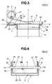
- the pivot shaft 3 is inserted into the elliptic shaft opening 17 of one of the first side wall portions 14, one of the bushes 4 which has been set in the opening 25 of one of the second side wall portions 24, the coil spring 5, the other bush 4 which has been set in the opening 25 of the other second side wall portion 24 and the elliptic shaft opening 17 of the other first side wall portion 14.
- the pivot shaft 3 is biased upward in the elliptic shaft openings 17.
- valve plate structure 2 is brought down to a position where the flat annular lower surface 26 is intimately pressed against the annular flat part 61 of the seal member 6. Then, keeping the valve plate structure 2 in the position, both ends of the pivot shaft 3 are welded at 31 to the first side wall portions 14 of the valve seat structure 1. With this, the pivot shaft 3 is secured to the first side wall portions 14 keeping the valve plate structure 2 pressed against the valve seat structure 1 due to the force of the coil spring 5.
- valve PSV-3 assumes a full close position wherein the peripheral area (viz., the annular flat sealing portion 22) of the circular valve plate portion 21 of the valve plate structure 2 is intimately pressed against the flat annular upper surface 16 of the seal member 6 on the valve seat structure 1.
- the elliptic shaft openings 17 of the first side wall portions 14 serve as a means for correcting the relative positioning between the valve seat structure 1 and the valve plate structure 2, and thus, upon completion of welding at the portions 31, a precise positioning is obtained therebetween thereby to obtain a high sealing performance in the full close position of the valve PSV-3.
- both the annular seat portion 12 of the valve seat structure 1 and the annular flat sealing portion 22 of the valve plate structure 2 are constructed flat. However, if desired, one of them may be an annular projection extending therearound.
- the annular seal member 6 is welded to the valve seat structure 1.
- the annular seal member 6 may be welded to the valve plate structure 2. That is, in this modification, an annular flat seal member (6) is welded to a lower surface (see Fig. 2) of the annular flat sealing portion 22 of the structure 2.
- tubular part 62 of the seal member 6 extends from an inner periphery of the annular flat part 61.
- such tubular part (62) may extend from an outer periphery of the annular flat part 61.
- the seal member 6 is secured to the valve seat structure 1 by means of welding.
- other connecting technique such as, bolt-and-nut and the like may be used.
- a pressed stainless wire mesh is used as the material of the seal member 6.
- pressed brass wire mesh or the like may be used in place of the pressed stainless wire mesh.
Landscapes
- Engineering & Computer Science (AREA)
- Chemical & Material Sciences (AREA)
- Combustion & Propulsion (AREA)
- Mechanical Engineering (AREA)
- General Engineering & Computer Science (AREA)
- Exhaust Silencers (AREA)
- Lift Valve (AREA)
- Check Valves (AREA)
Applications Claiming Priority (2)
| Application Number | Priority Date | Filing Date | Title |
|---|---|---|---|
| JP2000275073A JP2002089257A (ja) | 2000-09-11 | 2000-09-11 | 制御マフラ用バルブおよび制御マフラ用バルブの弁体組み付け方法 |
| JP2000275073 | 2000-09-11 |
Publications (3)
| Publication Number | Publication Date |
|---|---|
| EP1186756A2 true EP1186756A2 (de) | 2002-03-13 |
| EP1186756A3 EP1186756A3 (de) | 2003-11-19 |
| EP1186756B1 EP1186756B1 (de) | 2005-12-21 |
Family
ID=18760746
Family Applications (1)
| Application Number | Title | Priority Date | Filing Date |
|---|---|---|---|
| EP01121874A Expired - Lifetime EP1186756B1 (de) | 2000-09-11 | 2001-09-11 | Druckempfindliches Ventil für einen Abgasschalldämpfer und Montageverfahren dazu |
Country Status (4)
| Country | Link |
|---|---|
| US (1) | US6637449B2 (de) |
| EP (1) | EP1186756B1 (de) |
| JP (1) | JP2002089257A (de) |
| DE (1) | DE60116012T2 (de) |
Cited By (3)
| Publication number | Priority date | Publication date | Assignee | Title |
|---|---|---|---|---|
| FR2866062A1 (fr) * | 2004-02-05 | 2005-08-12 | Faurecia Sys Echappement | Dispositif d'obturation d'un conduit d'une ligne d'echappement |
| CN110748680A (zh) * | 2019-11-26 | 2020-02-04 | 天纳克(苏州)排放系统有限公司 | 排气阀 |
| CN111750120A (zh) * | 2019-03-29 | 2020-10-09 | 天纳克汽车经营有限公司 | 阻尼阀组件 |
Families Citing this family (22)
| Publication number | Priority date | Publication date | Assignee | Title |
|---|---|---|---|---|
| JP2002089256A (ja) * | 2000-09-20 | 2002-03-27 | Calsonic Kansei Corp | 制御マフラ用バルブ |
| FR2863659B1 (fr) * | 2003-12-16 | 2007-10-05 | Faurecia Sys Echappement | Dispositif d'obturation d'un conduit d'une ligne d'echappement |
| FR2863658B1 (fr) * | 2003-12-16 | 2007-10-12 | Faurecia Sys Echappement | Dispositif d'obturation de l'extremite d'un conduit d'une ligne d'echappement |
| JP4575172B2 (ja) * | 2005-01-04 | 2010-11-04 | 中央発條株式会社 | 排気流路制御弁 |
| US7426979B2 (en) * | 2005-01-12 | 2008-09-23 | Calsonic Kansei Corporation | Exhaust gas control valve |
| US20080083218A1 (en) * | 2006-10-06 | 2008-04-10 | Arvin Technologies, Inc. | Passive throttling valve outside of muffler |
| DE602006008646D1 (de) * | 2006-12-29 | 2009-10-01 | Magneti Marelli Spa | Schalldämpfer mit variabler Geometrie für ein Abgassystem eines Verbrennungsmotors |
| US9376947B2 (en) | 2007-03-29 | 2016-06-28 | Faurecia Emissions Control Technologies Usa, Llc | Hybrid valve for attenuation of low frequency noise |
| US8453672B2 (en) * | 2007-03-29 | 2013-06-04 | Emcon Technologies Llc | Passive valve for attenuation of low frequency noise |
| US7954509B2 (en) * | 2007-07-31 | 2011-06-07 | Honeywell International Inc. | Check valves with hinge shafts retained by welding |
| US7628250B2 (en) * | 2007-11-21 | 2009-12-08 | Emcon Technologies Llc | Passive valve assembly for vehicle exhaust system |
| CA2712687A1 (en) * | 2009-08-12 | 2011-02-12 | R700 Holdings Ltd. | Supercharger system for two-stroke engines |
| JP5484374B2 (ja) * | 2011-02-17 | 2014-05-07 | 本田技研工業株式会社 | 排気マフラー |
| US9540995B2 (en) | 2012-03-06 | 2017-01-10 | KATCON USA, Inc. | Exhaust valve assembly |
| CN107076003B (zh) | 2014-11-10 | 2019-05-07 | 双叶产业株式会社 | 切换阀 |
| JP6441658B2 (ja) * | 2014-12-17 | 2018-12-19 | フタバ産業株式会社 | 開閉装置 |
| KR101709706B1 (ko) * | 2015-10-14 | 2017-02-23 | 우신공업 주식회사 | 머플러용 배기 밸브 및 이를 포함한 머플러 |
| JP2019019787A (ja) * | 2017-07-20 | 2019-02-07 | カルソニックカンセイ株式会社 | 排気バルブ装置 |
| JP7006030B2 (ja) * | 2017-08-31 | 2022-01-24 | スズキ株式会社 | 排気装置 |
| US11149602B2 (en) * | 2018-05-22 | 2021-10-19 | Faurecia Emissions Control Technologies, Usa, Llc | Passive flap valve for vehicle exhaust system |
| FR3083033B1 (fr) * | 2018-06-22 | 2020-05-29 | Renault S.A.S | Machine electrique refroidie par un liquide caloporteur dielectrique |
| JP7359817B2 (ja) * | 2021-10-06 | 2023-10-11 | フタバ産業株式会社 | バルブの取り付け構造 |
Family Cites Families (18)
| Publication number | Priority date | Publication date | Assignee | Title |
|---|---|---|---|---|
| US2494016A (en) * | 1945-03-29 | 1950-01-10 | Taylor Charles Ralph | Exhaust pipe end cover |
| US2694358A (en) * | 1950-08-01 | 1954-11-16 | Anthes Force Oiler Company | Exhaust pipe cover |
| US2960178A (en) * | 1958-11-24 | 1960-11-15 | Gen Motors Corp | Engine exhaust system |
| AT233326B (de) * | 1962-07-12 | 1964-05-11 | Michael Guillermo Dipl Ing May | Verfahren und Einrichtung zur Verminderung der Anteile der unverbrannten und teilverbrannten Bestandteile in den Abgasen von fremdgezündeten Viertakt-Verbrennungskraftmaschinen |
| US3498322A (en) * | 1967-05-10 | 1970-03-03 | James P Gilliam | Check valve |
| US3870071A (en) * | 1974-01-16 | 1975-03-11 | Valve Syst Int Inc | Swing check seal assembly |
| FR2514412A1 (fr) * | 1981-10-14 | 1983-04-15 | Peugeot Cycles | Dispositif de modulation de l'ecoulement des gaz dans un silencieux d'echappement de moteur a combustion interne |
| GB8425657D0 (en) * | 1984-10-10 | 1984-11-14 | Austin Rover Group | Exhaust system |
| US5355673A (en) * | 1992-11-18 | 1994-10-18 | Sterling Robert E | Exhaust valve |
| WO1995013460A1 (en) * | 1993-11-09 | 1995-05-18 | Futaba Industrial Co., Ltd. | Muffler for an internal combustion engine |
| US5614699A (en) * | 1994-05-09 | 1997-03-25 | Nissan Motor Co., Ltd. | Automobile exhaust noise suppressor |
| JP3379254B2 (ja) * | 1994-12-26 | 2003-02-24 | 日産自動車株式会社 | 排気消音装置 |
| JP3248381B2 (ja) * | 1995-01-09 | 2002-01-21 | トヨタ自動車株式会社 | バタフライ弁 |
| US5712454A (en) * | 1995-01-27 | 1998-01-27 | Honda Giken Kogyo Kabushiki Kaisha | Exhaust system in internal combustion engine |
| JP3318496B2 (ja) * | 1996-10-29 | 2002-08-26 | 日産自動車株式会社 | 自動車用排気マフラー |
| JP4008101B2 (ja) * | 1998-05-06 | 2007-11-14 | カルソニックカンセイ株式会社 | 排気系バルブの弁体組み付け方法と排気系バルブ |
| JP3153798B2 (ja) * | 1998-06-16 | 2001-04-09 | 株式会社三五 | エンジンのマフラにおける排気管用バルブ |
| DE69902085T2 (de) * | 1999-02-18 | 2003-01-30 | Hyundai Motor Co., Seoul/Soul | Semiaktiver Schalldämpfer für Brennkraftmaschine |
-
2000
- 2000-09-11 JP JP2000275073A patent/JP2002089257A/ja active Pending
-
2001
- 2001-09-11 DE DE60116012T patent/DE60116012T2/de not_active Expired - Fee Related
- 2001-09-11 EP EP01121874A patent/EP1186756B1/de not_active Expired - Lifetime
- 2001-09-12 US US09/949,828 patent/US6637449B2/en not_active Expired - Fee Related
Cited By (5)
| Publication number | Priority date | Publication date | Assignee | Title |
|---|---|---|---|---|
| FR2866062A1 (fr) * | 2004-02-05 | 2005-08-12 | Faurecia Sys Echappement | Dispositif d'obturation d'un conduit d'une ligne d'echappement |
| WO2005075862A1 (fr) * | 2004-02-05 | 2005-08-18 | Faurecia Systemes D'echappement, Societe Par Actions Simplifiee | Dispositif d 'obturation d'un conduit d'une ligne d'echappement |
| CN111750120A (zh) * | 2019-03-29 | 2020-10-09 | 天纳克汽车经营有限公司 | 阻尼阀组件 |
| CN111750120B (zh) * | 2019-03-29 | 2023-06-09 | 天纳克汽车经营有限公司 | 阻尼阀组件 |
| CN110748680A (zh) * | 2019-11-26 | 2020-02-04 | 天纳克(苏州)排放系统有限公司 | 排气阀 |
Also Published As
| Publication number | Publication date |
|---|---|
| EP1186756B1 (de) | 2005-12-21 |
| EP1186756A3 (de) | 2003-11-19 |
| DE60116012D1 (de) | 2006-01-26 |
| JP2002089257A (ja) | 2002-03-27 |
| US6637449B2 (en) | 2003-10-28 |
| US20020029807A1 (en) | 2002-03-14 |
| DE60116012T2 (de) | 2006-06-29 |
Similar Documents
| Publication | Publication Date | Title |
|---|---|---|
| EP1186756B1 (de) | Druckempfindliches Ventil für einen Abgasschalldämpfer und Montageverfahren dazu | |
| JP4624788B2 (ja) | 多方向タービンシムシール | |
| US5630571A (en) | Exhaust flow control valve | |
| US11333255B2 (en) | Valve assembly | |
| JP3558792B2 (ja) | インテークマニホールドと吸気制御装置及びその製造方法 | |
| JP3326743B2 (ja) | 排気流路制御弁 | |
| US10662868B2 (en) | Regulating device for a turbocharger | |
| EP1408206B1 (de) | Ventilvorrichtung für Schalldämpfer | |
| JPH06575Y2 (ja) | 内燃機関用マフラー | |
| WO1993025804A1 (en) | Internal combustion engine exhaust control valve | |
| CN115324749B (zh) | 用于车辆的排气系统的阀组件 | |
| KR20040045366A (ko) | 내연 기관의 배기 가스 재순환 장치 | |
| WO2021021471A1 (en) | Externally mounted in-line exhaust gas valve | |
| JPH0643227U (ja) | ターボチャージャ用ウェイストゲートバルブ | |
| US20230193796A1 (en) | Muffler valve and muffler | |
| JP6981952B2 (ja) | 排気熱回収器 | |
| KR19990082800A (ko) | 압력제어밸브 | |
| EP1422411B1 (de) | Abgasrückführungsvorrichtung für eine Brennkraftmaschine | |
| JP4144149B2 (ja) | 自動車用排気消音装置 | |
| EP1262646A2 (de) | Ventilvorrichtung | |
| JPH0439388Y2 (de) | ||
| WO2021007005A1 (en) | Valve assembly | |
| JP4628271B2 (ja) | 可変吸気装置のシール構造 | |
| US11428153B2 (en) | Turbocharger | |
| JP2001207827A (ja) | 排気流路制御弁 |
Legal Events
| Date | Code | Title | Description |
|---|---|---|---|
| PUAI | Public reference made under article 153(3) epc to a published international application that has entered the european phase |
Free format text: ORIGINAL CODE: 0009012 |
|
| 17P | Request for examination filed |
Effective date: 20010911 |
|
| AK | Designated contracting states |
Kind code of ref document: A2 Designated state(s): AT BE CH CY DE DK ES FI FR GB GR IE IT LI LU MC NL PT SE TR |
|
| AX | Request for extension of the european patent |
Free format text: AL;LT;LV;MK;RO;SI |
|
| PUAL | Search report despatched |
Free format text: ORIGINAL CODE: 0009013 |
|
| AK | Designated contracting states |
Kind code of ref document: A3 Designated state(s): AT BE CH CY DE DK ES FI FR GB GR IE IT LI LU MC NL PT SE TR |
|
| AX | Request for extension of the european patent |
Extension state: AL LT LV MK RO SI |
|
| 17Q | First examination report despatched |
Effective date: 20040212 |
|
| AKX | Designation fees paid |
Designated state(s): DE FR GB |
|
| GRAP | Despatch of communication of intention to grant a patent |
Free format text: ORIGINAL CODE: EPIDOSNIGR1 |
|
| GRAS | Grant fee paid |
Free format text: ORIGINAL CODE: EPIDOSNIGR3 |
|
| GRAA | (expected) grant |
Free format text: ORIGINAL CODE: 0009210 |
|
| AK | Designated contracting states |
Kind code of ref document: B1 Designated state(s): DE FR GB |
|
| REG | Reference to a national code |
Ref country code: GB Ref legal event code: FG4D |
|
| REF | Corresponds to: |
Ref document number: 60116012 Country of ref document: DE Date of ref document: 20060126 Kind code of ref document: P |
|
| ET | Fr: translation filed | ||
| PLBE | No opposition filed within time limit |
Free format text: ORIGINAL CODE: 0009261 |
|
| STAA | Information on the status of an ep patent application or granted ep patent |
Free format text: STATUS: NO OPPOSITION FILED WITHIN TIME LIMIT |
|
| 26N | No opposition filed |
Effective date: 20060922 |
|
| PGFP | Annual fee paid to national office [announced via postgrant information from national office to epo] |
Ref country code: GB Payment date: 20070917 Year of fee payment: 7 |
|
| PGFP | Annual fee paid to national office [announced via postgrant information from national office to epo] |
Ref country code: DE Payment date: 20071030 Year of fee payment: 7 |
|
| PGFP | Annual fee paid to national office [announced via postgrant information from national office to epo] |
Ref country code: FR Payment date: 20070914 Year of fee payment: 7 |
|
| GBPC | Gb: european patent ceased through non-payment of renewal fee |
Effective date: 20080911 |
|
| REG | Reference to a national code |
Ref country code: FR Ref legal event code: ST Effective date: 20090529 |
|
| PG25 | Lapsed in a contracting state [announced via postgrant information from national office to epo] |
Ref country code: DE Free format text: LAPSE BECAUSE OF NON-PAYMENT OF DUE FEES Effective date: 20090401 |
|
| PG25 | Lapsed in a contracting state [announced via postgrant information from national office to epo] |
Ref country code: FR Free format text: LAPSE BECAUSE OF NON-PAYMENT OF DUE FEES Effective date: 20080930 |
|
| PG25 | Lapsed in a contracting state [announced via postgrant information from national office to epo] |
Ref country code: GB Free format text: LAPSE BECAUSE OF NON-PAYMENT OF DUE FEES Effective date: 20080911 |