EP1187152B1 - Kontaktloser Drehverbinder - Google Patents
Kontaktloser Drehverbinder Download PDFInfo
- Publication number
- EP1187152B1 EP1187152B1 EP01307343A EP01307343A EP1187152B1 EP 1187152 B1 EP1187152 B1 EP 1187152B1 EP 01307343 A EP01307343 A EP 01307343A EP 01307343 A EP01307343 A EP 01307343A EP 1187152 B1 EP1187152 B1 EP 1187152B1
- Authority
- EP
- European Patent Office
- Prior art keywords
- rotary
- light emitting
- stationary
- side light
- rotating
- Prior art date
- Legal status (The legal status is an assumption and is not a legal conclusion. Google has not performed a legal analysis and makes no representation as to the accuracy of the status listed.)
- Expired - Lifetime
Links
- 230000003287 optical effect Effects 0.000 claims abstract description 19
- 238000004891 communication Methods 0.000 claims description 23
- 238000004804 winding Methods 0.000 claims description 12
- 230000008878 coupling Effects 0.000 abstract description 5
- 238000010168 coupling process Methods 0.000 abstract description 5
- 238000005859 coupling reaction Methods 0.000 abstract description 5
- 230000005540 biological transmission Effects 0.000 abstract description 4
- 238000010586 diagram Methods 0.000 description 7
- 238000000034 method Methods 0.000 description 6
- 230000008054 signal transmission Effects 0.000 description 4
- 239000003990 capacitor Substances 0.000 description 3
- 210000000352 storage cell Anatomy 0.000 description 3
- 230000002457 bidirectional effect Effects 0.000 description 2
- 244000045947 parasite Species 0.000 description 2
- 230000005674 electromagnetic induction Effects 0.000 description 1
- 238000005516 engineering process Methods 0.000 description 1
- 230000007613 environmental effect Effects 0.000 description 1
- 230000006872 improvement Effects 0.000 description 1
- 238000009434 installation Methods 0.000 description 1
- 230000007246 mechanism Effects 0.000 description 1
- 229920003023 plastic Polymers 0.000 description 1
- 239000004033 plastic Substances 0.000 description 1
- 239000007787 solid Substances 0.000 description 1
Images



Classifications
-
- H—ELECTRICITY
- H01—ELECTRIC ELEMENTS
- H01F—MAGNETS; INDUCTANCES; TRANSFORMERS; SELECTION OF MATERIALS FOR THEIR MAGNETIC PROPERTIES
- H01F38/00—Adaptations of transformers or inductances for specific applications or functions
- H01F38/18—Rotary transformers
-
- H—ELECTRICITY
- H04—ELECTRIC COMMUNICATION TECHNIQUE
- H04B—TRANSMISSION
- H04B10/00—Transmission systems employing electromagnetic waves other than radio-waves, e.g. infrared, visible or ultraviolet light, or employing corpuscular radiation, e.g. quantum communication
- H04B10/80—Optical aspects relating to the use of optical transmission for specific applications, not provided for in groups H04B10/03 - H04B10/70, e.g. optical power feeding or optical transmission through water
- H04B10/801—Optical aspects relating to the use of optical transmission for specific applications, not provided for in groups H04B10/03 - H04B10/70, e.g. optical power feeding or optical transmission through water using optical interconnects, e.g. light coupled isolators, circuit board interconnections
-
- H—ELECTRICITY
- H01—ELECTRIC ELEMENTS
- H01F—MAGNETS; INDUCTANCES; TRANSFORMERS; SELECTION OF MATERIALS FOR THEIR MAGNETIC PROPERTIES
- H01F38/00—Adaptations of transformers or inductances for specific applications or functions
- H01F38/14—Inductive couplings
Definitions
- the present invention relates to a rotary contactless connector. More particularly, the present invention relates to a novel improvement for implementing contactless optical communication type single-channel or multi-channel signal transmission by using the rotary contactless connector and the non-rotary contactless connector.
- a rotor of a rotary transformer is equipped with a rotating-side light emitting or light receiving element, and electric power from an external source is supplied through the intermediary of the rotary transformer to an electric circuit for driving and controlling the rotating-side light emitting element light receiving element.
- the electric power from an external source is supplied through the intermediary of a transformer to an electric circuit for driving a light emitting element or a light receiving element at a power-supplied side.
- signal transmission between a stationary-side unit and a rotating-side unit has been effected by connecting, for example, a rotating-side unit mounted on a gimbal mechanism having a plurality of rotating shafts or a single-shaft rotating platform and a stationary-side unit by using a rotary joint or slip ring and a contact connection type connector, and eventually by direct coupling to the contact connection type connector.
- a rotary contactless connector can be found in US-A-5 818 188 .
- connection method based on a contact type connector and the direct coupling wiring method for connecting a stationary unit and a rotating unit inevitably produce parasite drag generated due to the twist or rigidity of wiring even when only rotary motion of a finite angle is involved.
- the rotary joint or slip ring method has been posing such problems as larger sizes, higher cost, and lower environmental resistance although it has less likelihood of the occurrence of the parasite drag attributable to the twist or rigidity of wiring.
- the present invention has been made with a view toward solving the above problems, and it is an object of the present invention to provide a rotary contactless connector adapted to perform optical communication type single- or multi-channel signal transmission in a contactless condition.
- a rotary contactless connector as set out in Claim 1.
- Preferred features of the invention are set out in Claims 2 to 6.
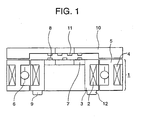
- reference numeral 1 denotes a rotary transformer acting as a contactless power supplying unit.
- the rotary transformer 1 is comprised of a hollow (or solid) rotor 3 having a transformer rotor-side winding 2, and an annular stator 5 that is provided concentrically with the rotor 3 and around the outer periphery of the rotor 3 and has a transformer stator-side winding 4.
- a nonmagnetic and non-magnetized bearing 6 formed of a plastics or the like is provided on the inner wall of the annular stator 5.
- the nonmagnetic and non-magnetized bearing 6 is disposed between the annular stator 5 and the rotor 3. If the bearing 6 is not used, then it is possible to connect the rotor 3 to a rotating member of an apparatus and connect the annular stator 5 to a stationary member of the apparatus, thereby to put the rotor 3 and the annular stator 5 in order.
- One or a plurality of light emitting elements 8 (or light receiving elements) of a rotating assembly are provided on a mounting plate 7.
- the mounting plate 7 is provided on the orthogonal surface of the rotor 3 to the axial direction of the rotating shaft of the rotor 3.
- An electric circuit 9 for driving the light emitting element (or receiving elements) 8 on the rotating assembly is mounted on the rotor 3, and the electric power can be supplied from outside via the rotary transformer 1.
- the electric circuit 9 may alternatively be provided on a rotating member other than the rotor 3. It is needless to say that the electric power supplied via the rotary transformer 1 can be supplied to other general circuits (not shown) in addition to the light emitting elements and light receiving elements.
- a stationary member 10 is provided on the surface of the annular stator 5 such that it opposes the rotor 3. Inside the stationary member 10, one or a plurality of stationary-side light receiving elements (or light emitting elements) 11 are provided to correspond to the rotating-side light emitting elements 8.
- the stationary member 10 can be secured to the annular stator 5 or attached to a stationary unit of an apparatus (not shown).
- the electric circuit 9 receives data sent from an apparatus in a rotary unit.
- the electric circuit 9 sends the emitting signals to the rotating-side light emitting elements 8, the rotating-side light emitting elements 8 emit light corresponding to the drive data signals, and the emitted light is received by the stationary-side light receiving elements 11.
- the data is transmitted from the rotating-side light emitting elements 8 to the stationary-side light receiving elements 11 by the optical communication method, allowing the contactless system to accomplish the same operation performed by a mechanical connector or slip ring.
- the dispositional relationship between the rotating-side light emitting elements 8 and the stationary-side light receiving elements 11 can be reversed, as previously mentioned.
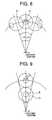
- Fig. 5 through Fig. 9 illustrate the relationship between the output range (denoted by r) of the rotating-side light emitting elements 8 and the light receiving range (denoted by R) of the stationary-side light receiving elements 11. It is possible to provide one element 8 and one element 11 at a central position to handle one channel. As shown in Fig. 5 and Fig. 6 , however, if four rotating-side light emitting elements 8 and six stationary-side light receiving elements 11 are provided at concentric circumferential positions other than the central position, then it is also possible to provide a plurality of the elements 8 and 11 in the radial direction, as shown in Fig. 9 .
- the four rotating-side light emitting elements 8 are set to 2.1, 2.2, 2.3, and 2.4 to assign them to channel 1, channel 2, channel 3, and channel 4, respectively.
- the output range of light emitting element 8 at the surface of the stationary-side light receiving elements 11 is denoted by a radius "r". Since four-channel outputs are required, it is necessary to provide four rotating-side light emitting elements 8. In order to restrain the occurrence of interruption and interference in receiving data, it is required to provide six stationary-side light receiving elements 11 (3.1, 3.2, 3.3, 3.4, 3.5, and 3.6) of the light receiving radius "R" at the apexes of an equilateral hexagon about a rotational axis. Referring to Fig.
- Optical communication can be performed by switching the outputs of the light receiving elements in sequence on the basis of a rotational angle in the similar manner as that described above.
- a rotating unit provides 2-channel outputs in the case of a finite-angle rotation. If two channels are on the same circumference, then three stationary-side light receiving elements 11 are installed, and the output of the middle stationary-side light receiving element 11 is switched on the basis of a rotational angle, as shown in Fig. 7 , to perform optical communication. The same applies to the case shown in Fig. 8 where r>R.
- the light emitting elements 8 are on the same circumference.
- the light emitting elements for two channels is installed on two concentric circles, one on each, in the radial direction rather than on the same circumference, two-way, optical data communication will be possible as shown in Fig. 9 .
- the optical communication based on the contactless data transmission can be achieved by properly disposing the light emitting elements and light receiving elements and appropriately switching the outputs of the optical elements by an electronic switching circuit or the like of the electric circuit 9.
- a rotary contactless connector can be obtained by combining a contactless power supplying unit and a contactless data communication unit.
- stator 5 is positioned around the outer periphery of the rotor 3 to represent a case where the rotor is located inside the stator. There are cases, however, where the rotor is located outside the stator, so that the stator 5 may be positioned on the inner periphery of the rotor 3. These cases are also included in the present invention.
- a nonmagnetic and non-magnetized bearing 6 is provided on the inner wall (or the outer wall if the stator 5 is position on the inner periphery of the rotor 3) of the annular stator 5.
- the nonmagnetic and non-magnetized bearing 6 is disposed between the annular stator 5 and the rotor 3. If the bearing 6 is not used, then it is possible to connect the rotor 3 to a rotating member of an apparatus to which the connector is applied, and connect the annular stator 5 to a stationary member of the apparatus, to which the connector is applied, thereby positioning the rotor 3 and the annular stator 5.
- An electric circuit 9 for driving the rotating-side light emitting element (or light receiving elements) 8 is mounted at an end of the rotor 3, and the electric power can be supplied from outside via the rotary transformer 1.
- the electric circuit 9 may alternatively be provided on a rotating member of the apparatus, to which the connector is applied, other than the rotor 3.
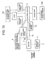
- the electric power from an external source which has passed through the rotary transformer 1 is supplied to the electric circuit 9 directly or through the intermediary of a storage means 12, as shown in Fig. 10 , and can be supplied to other general unit 301 in addition to the light emitting elements and light receiving elements.
- the storage means 12 is composed of a capacitor or a storage cell, such as a battery.
- the storage means 12 has a buffer function for a power system.
- Fig. 10 shows the configuration wherein a rotational angle sensor 300, which may be composed of the light emitting elements 8 and light receiving elements 11 itself, and a rotating-side general unit 301 have been connected to the rotary transformer 1 shown in Fig. 1 .
- the electric power from an external source is supplied to the electric circuit 9 through the intermediary of the storage means 12.
- the electric power from the storage means 12 can be supplied to the rotating-side light emitting elements 8 and the rotating-side general unit 301 via the electric circuit 9.
- the power output end of the rotary transformer 1 is divided into one end 1a and the other end 1b, and the one end 1a is directly connected to the electric circuit 9, while the other end 1b is connected to the electric circuit 9 through the intermediary of the storage means 12.
- a stationary member 10 is provided to cover the rotor 3 and the annular stator 5.
- One or a plurality of light receiving elements 11 (or light emitting elements) of the stationary side are provided at the positions of the stationary member 10 that optically oppose the rotating-side light emitting elements 8 (or light receiving elements).
- the stationary member 10 may be fixed to the annular stator 5 or mounted on the stationary unit of an apparatus (not shown).
- the electric circuit 9 receives data sent from an apparatus in a rotary unit.
- the electric circuit 9 sends the emitting signals to the rotating-side light emitting elements 8 (hereinafter, the rotating assembly will have the light emitting elements), the rotating-side light emitting elements 8 emit light corresponding to the drive data signals, and the emitted signals are received by the stationary-side light receiving elements 11 (hereinafter, the stationary unit will have the light receiving elements).
- the data is transmitted from the rotating-side light emitting elements 8 to the stationary-side light receiving elements 11 by optical communication method, allowing the contactless system to accomplish the same operation performed by a mechanical connector or slip ring.
- the dispositional relationship between the light emitting elements 8 and the light receiving elements 11 can be reversed, and provided side by side, thus enabling multi-channel bidirectional optical communication to be achieved.
- the data signals to emit to the rotating-side light emitting elements 8 and to be received by the stationary-side light receiving elements 11 can be taken out electromagnetically to the outside through the intermediary of the transformer rotor winding 2 or the transformer stator winding 4.
- a multi-channel bidirectional electromagnetical communication may be achieved.
- Fig. 11 shows the not claimed configuration of a non-rotary contactless connector.
- first stationary member 101 is set as the rotating member in the foregoing rotary contactless connector
- second stationary member 103 is set as the stationary member in the foregoing rotary contactless connector (the relationship may be reversed)
- the gap between the stationary members 101 and 103 corresponds to the gap between the rotor 3 and the annular stator 5 of the foregoing rotary contactless connector shown in Fig. 1 .
- the rotary transformer 1 in the aforesaid rotary contactless connector shown in Fig. 10 corresponds to a stationary transformer 200, and the correspondence of the individual components of the rotating assembly and the stationary unit will be as follows.
- the foregoing transformer rotor winding 2 which is a component of the rotating assembly, corresponds to a first transformer winding 100
- the foregoing rotor 3 and the mounting plate 7 correspond to the first stationary member 101
- the foregoing rotating-side light emitting element 8 corresponds to a first light emitting element 110 (here, a first stationary member 101 will have the light emitting elements)
- the foregoing electric circuit 9 corresponds to an electric circuit 120
- the foregoing storage means 12 composed of a capacitor or a storage cell corresponds to a storage means 130 composed of a capacitor or a storage cell.
- the foregoing transformer stator winding 4 corresponds to a second transformer winding 102
- the foregoing annular stator 5 and the stationary member 10 correspond to a second stationary member 103
- the foregoing light receiving element 11 on the stationary unit corresponds to a second light receiving element 111 (here, a second stationary member 111 will have the light receiving elements).
- the electric power supplied to the electric circuit 120 by making use of the electromagnetic induction between the transformer windings 100 and 102 is supplied to the first light emitting element 110 through wiring (not shown), and can also be supplied to other general devices or the like in the power-supplied unit (not shown) by the electromagnetic coupling previously mentioned.
- the signals to emit to the first light emitting element 110 and to be received by the second light receiving element 111 can be taken out electromagnetically to the outside through the transformer winding 100 or 102.
- the non-rotary contactless connector and the rotary contactless connector basically share the same configuration and function except for the disposition of the light emitting elements and receiving elements for data communication. More specifically, the non-rotary contactless connector has no changes in relative position, so that simply installing it at an opposing position obviates the need for switching.
- the meaning of the term “contactless” also includes a condition wherein the first stationary member 101 and the second stationary member 103 shown in Fig. 11 are "in contact” on the contactless surface D whereon the first light emitting element 110 and the second light receiving element 111 oppose each other.
- the designation, non-rotary "contactless" connector implies that the connector is able to function also in the contactless condition.
- the configuration of the electric power source depends on a required condition of the electric power to be consumed.
- whether the configuration in which the electric power going through the intermediary of the rotary transformer 1 in the case of the rotary contactless connector or through the stationary transformer 200 in the case of the non-rotary contactless connector is always supplied directly to the electric circuit 9 or 120, or the configuration in which the electric power is supplied to the electric circuit 9 or 120 always through the intermediary of the storage means should be selected according to a required condition of the electric power to be consumed.
- the above configurations are obviously included in the configurations wherein the output power of the rotary transformer or the stationary transformer is supplied to the electric circuit directly and through the intermediary of the storage means.
- the electric circuit functions to supply electric power, generate light emitting commands and light receiving signals, and switch optical elements on the basis of rotational angles (the switching applies only to the rotary contactless connector).
- the functions are not described because the installation place of the electric circuit should not limited to within the connector.
- the existence of the storage means for the input of the electric circuit on the stationary unit remains optional. In the configurations shown in Fig. 1 through Fig. 11 , the communication light between the light emitting elements and the light receiving elements advances in parallel to the axial direction of the rotating shaft.
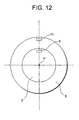
- the rotating-side light emitting element 8 provided on the rotor 3 and the light receiving element 11 on the stationary unit provided on the annular stator 5 can be positioned on the same plane so that they oppose each other, as shown in Fig. 12 , the light path direction of the communication light between the elements 8 and 11 can be made orthogonal to the axial direction of the rotating shaft of the rotor 3.
- the rotary contactless connector in accordance with the present invention provides the following advantages.
- the combination of the rotary transformer and the means for coupling optical elements allows data communication between the optical elements in a contactless mode while receiving electric power supplied from an external source.
- This arrangement makes it possible to transfer data easily and reliably in the contactless mode in detectors, drive units, etc. in various types of apparatuses.
- the supply of electric power and the transfer of signals can be accomplished in the contactless mode under a restricted condition.
Landscapes
- Engineering & Computer Science (AREA)
- Power Engineering (AREA)
- Physics & Mathematics (AREA)
- Electromagnetism (AREA)
- Computer Networks & Wireless Communication (AREA)
- Signal Processing (AREA)
- Optical Communication System (AREA)
- Photo Coupler, Interrupter, Optical-To-Optical Conversion Devices (AREA)
- Coupling Device And Connection With Printed Circuit (AREA)
- Arrangements For Transmission Of Measured Signals (AREA)
- Mechanical Coupling Of Light Guides (AREA)
Claims (6)
- Kontaktloser Drehverbinder, der Folgendes umfasst:einen Drehtransformator (1), der aus seinem Läufer (3), der eine Transformatorläuferwicklung (2) hat, und einem ringförmigen Ständer (5), der konzentrisch mit dem Läufer (3) ist und eine Transformatorständerwicklung (4) hat, besteht, wobei der ringförmige Ständer (5) auf einer Außenseite des Läufers (3) angeordnet ist.ein Drehseiten-Lichtemissionselement (8) oder ein Drehseiten-Lichtempfangselement, das auf einer Oberfläche des Läufers (3) bereitgestellt wird, die senkrecht zu der Drehachse des Läufers (3) ist, undein Pestseiten-Lichtemissionseleznent oder ein Festseiten-Lichtempfangselement (11), das unbeweglich auf einer Oberfläche eines feststehenden Elements (10) angeordnet ist, die senkrecht zu der Drehachse des Läufers (3) ist, das dem Drehseiten-Lichtemissionselement (8) oder dem Drehseiten-Lichtempfangselement gegenüberliegt,wobei das Festseiten-Liehtemissionselement oder das Festseiten-Lichtempfangseleznent (11) in einem Aussparungsabschnitt des feststehenden Elements (10) angeordnet ist und dem Läufer (3) durch den Drehtransformator (1) Elektroenergie zugeführt wird, um eine optische Kommunikation durchzuführen.
- Kontaktloser Drehverbinder nach Anspruch 1, wobei ein nichtmagnetisches und nicht magnetisiertes Lager (6) zwischen dem Läufer (3) und dem ringförmigen Ständer (5) bereitgestellt wird.
- Kontaktloser Drehverbinder nach Anspruch 1, der ferner einen elektrischen Schaltkreis (9) zum Ansteuern des Drehseiten- Lichtemissionselements (8) oder des Drehseiten-Lichtempfangselements umfasst,
wobei die Elektroenergie dem elektrischen Schaltkreis (9) durch die Vermittlung des Drehtransformators zugeführt wird. - Kontaktloser Drehverbinder nach Anspruch 3, wobei der elektrische Schaltkreis (9) in dem Läufer (3) bereitgestellt wird.
- Kontaktloser Drehverbinder nach Anspruch 1, wobei mehrere der Drehseiten-Lichtemissionselemente (8) oder der Drehseiten-Lichtempfangselemente in der Radialrichtung des Läufers (3) bereitgestellt werden.
- Kontaktloser Drehverbinder nach Anspruch 1, wobei vier Drehseiten-Lichtemissionselemente bereitgestellt werden und sechs Festseiten-Lichtempfangselemente bereitgestellt werden, wobei die sechs Festseiten-Lichtempfangselemente an den Eckpunkte eines imaginären gleichseitigen Sechsecks angeordnet sind.
Applications Claiming Priority (4)
| Application Number | Priority Date | Filing Date | Title |
|---|---|---|---|
| JP2000259051 | 2000-08-29 | ||
| JP2000259051A JP3598053B2 (ja) | 2000-08-29 | 2000-08-29 | 回転型非接触コネクタ |
| JP2001076684A JP3533375B2 (ja) | 2001-03-16 | 2001-03-16 | 回転型非接触コネクタ |
| JP2001076684 | 2001-03-16 |
Publications (4)
| Publication Number | Publication Date |
|---|---|
| EP1187152A2 EP1187152A2 (de) | 2002-03-13 |
| EP1187152A3 EP1187152A3 (de) | 2003-11-26 |
| EP1187152B1 true EP1187152B1 (de) | 2010-08-18 |
| EP1187152B8 EP1187152B8 (de) | 2010-12-15 |
Family
ID=26598683
Family Applications (1)
| Application Number | Title | Priority Date | Filing Date |
|---|---|---|---|
| EP01307343A Expired - Lifetime EP1187152B8 (de) | 2000-08-29 | 2001-08-29 | Kontaktloser Drehverbinder |
Country Status (4)
| Country | Link |
|---|---|
| US (1) | US6759759B2 (de) |
| EP (1) | EP1187152B8 (de) |
| AT (1) | ATE478428T1 (de) |
| DE (1) | DE60142819D1 (de) |
Families Citing this family (26)
| Publication number | Priority date | Publication date | Assignee | Title |
|---|---|---|---|---|
| DE10302435B3 (de) * | 2003-01-21 | 2004-07-01 | Schleifring Und Apparatebau Gmbh | Optischer Gigabit-Drehübertrager mit freiem Innendurchmesser |
| JP2006108337A (ja) | 2004-10-05 | 2006-04-20 | Chubu Nippon Maruco Kk | 非接触コネクタ |
| KR100944743B1 (ko) * | 2005-07-08 | 2010-03-03 | 파나소닉 전공 주식회사 | 이중 배선 시스템용 베이스 유닛 |
| US7194154B2 (en) * | 2005-08-15 | 2007-03-20 | Sony Ericsson Mobile Communications Ab | Optical connector |
| US7957786B2 (en) * | 2005-08-15 | 2011-06-07 | General Electric Company | Methods and apparatus for communicating signals between portions of an apparatus in relative movement to one another |
| KR100800076B1 (ko) * | 2005-09-27 | 2008-01-31 | 추부 니혼 마루코 컴퍼니 리미티드 | 비접촉 커넥터 |
| US20070077783A1 (en) * | 2005-09-30 | 2007-04-05 | Trw Automotive U.S. Llc | Rotary connector system |
| JP4080503B2 (ja) * | 2005-10-03 | 2008-04-23 | 中部日本マルコ株式会社 | 非接触コネクタ |
| US7813602B2 (en) * | 2007-09-10 | 2010-10-12 | Chubu Nihon Maruko Co., Ltd. | Non-contact connector |
| JP2009130773A (ja) * | 2007-11-27 | 2009-06-11 | Chubu Nippon Maruco Kk | 非接触コネクタ |
| EP2073408B1 (de) * | 2007-12-17 | 2012-08-08 | Siemens Aktiengesellschaft | Vorrichtung zum Übertragen von Lichtsignalen und entsprechendes Verfahren |
| DE102008008113A1 (de) * | 2008-02-08 | 2009-08-13 | Schaeffler Kg | Nichtmagnetisierbares Wälzlagerbauteil aus einem austenitischen Werkstoff und Verfahren zur Herstellung eines derartigen Wälzlagerbauteils |
| US20100148505A1 (en) * | 2008-12-16 | 2010-06-17 | Dunlap Gregory M | Contact-less power and signal transmission device for a high power level transformer |
| WO2010124165A1 (en) * | 2009-04-23 | 2010-10-28 | Battelle Memorial Institute | Inductively and optically coupled interconnect |
| DE102009053584A1 (de) | 2009-11-17 | 2011-05-19 | Airbus Operations Gmbh | Trägersystem zum Aufnehmen von Behältern in einem Fahrzeug und Verwendung eines Trägersystems in einem Flugzeug |
| US8041225B2 (en) * | 2009-12-21 | 2011-10-18 | General Electric Company | Contactless infrared data transmission for wind turbines |
| JP2011205878A (ja) * | 2009-12-25 | 2011-10-13 | Canon Anelva Corp | 真空アクチュエータ及び基板搬送ロボット |
| DE102011005339A1 (de) * | 2011-03-10 | 2012-09-13 | Komet Group Gmbh | Drehübertrager für Werkzeugmaschinen |
| US8953298B2 (en) | 2011-11-30 | 2015-02-10 | Taiwan Semiconductor Manufacturing Co., Ltd. | Electrostatic chuck robotic system |
| TWI551870B (zh) * | 2015-02-26 | 2016-10-01 | 思達科技股份有限公司 | 測試組件與其製作方法 |
| FR3056366B1 (fr) * | 2016-09-20 | 2019-08-30 | Thales | Collecteur tournant |
| US12414952B2 (en) | 2018-11-20 | 2025-09-16 | Merck Sharp & Dohme Llc | Substituted amino triazolopyrimidine and amino triazolopyrazine adenosine receptor antagonists, pharmaceutical compositions and their use |
| AU2019383948A1 (en) | 2018-11-20 | 2021-05-20 | Merck Sharp & Dohme Llc | Substituted amino triazolopyrimidine and amino triazolopyrazine adenosine receptor antagonists, pharmaceutical compositions and their use |
| WO2020112700A1 (en) | 2018-11-30 | 2020-06-04 | Merck Sharp & Dohme Corp. | 9-substituted amino triazolo quinazoline derivatives as adenosine receptor antagonists, pharmaceutical compositions and their use |
| AU2019388872A1 (en) | 2018-11-30 | 2021-05-27 | Merck Sharp & Dohme Llc | 7-, 8-, and 10-substituted amino triazolo quinazoline derivatives as adenosine receptor antagonists, pharmaceutical compositions and their use |
| CN117650843B (zh) * | 2024-01-30 | 2024-04-30 | 陕西旋星电子科技有限公司 | 一种非接触光通信滑环及其光器件侧面布置方法 |
Family Cites Families (14)
| Publication number | Priority date | Publication date | Assignee | Title |
|---|---|---|---|---|
| DE2752783C2 (de) * | 1977-11-25 | 1979-08-30 | Siemens Ag, 1000 Berlin Und 8000 Muenchen | Gerät zum Erfassen und Verarbeiten von elektrischen Signalen |
| JPS58142509A (ja) * | 1982-02-19 | 1983-08-24 | Hitachi Ltd | 回転部分を有する自動車部品への電源供給装置 |
| US4837556A (en) * | 1985-04-15 | 1989-06-06 | Kabushiki Kaisha Nihon Denzai Kogyo Kenkyusho | Signal transmission device |
| US4778147A (en) * | 1985-07-27 | 1988-10-18 | Mitsubishi Jidosha Kogyo Kabushiki Kaisha | Electromagnetic solenoid |
| JPH0747957Y2 (ja) * | 1987-03-31 | 1995-11-01 | トツパン・ム−ア株式会社 | 非接触式電力供給装置 |
| US5031992A (en) * | 1989-08-18 | 1991-07-16 | Ampex Corporation | Multiple parallel channel rotary optical coupler |
| US5331354A (en) * | 1990-09-26 | 1994-07-19 | Matsushita Electric Industrial Co., Ltd. | Power supply apparatus for television receiver set and television receiver set including the same |
| JP3116418B2 (ja) * | 1991-05-21 | 2000-12-11 | 株式会社安川電機 | 無接触給電装置 |
| US5637973A (en) * | 1992-06-18 | 1997-06-10 | Kabushiki Kaisha Yaskawa Denki | Noncontacting electric power transfer apparatus, noncontacting signal transfer apparatus, split-type mechanical apparatus employing these transfer apparatus and a control method for controlling same |
| FR2709618B1 (fr) * | 1993-07-28 | 1995-09-29 | Hispano Suiza Sa | Dispositif de transmission de signaux électriques de puissance à un ensemble tournant. |
| JPH07222489A (ja) * | 1994-01-27 | 1995-08-18 | Matsushita Electric Ind Co Ltd | モータ駆動装置 |
| US5521444A (en) * | 1994-11-30 | 1996-05-28 | Honeywell Inc. | Apparatus for transferring electrical power from a stationary device to a rotating device without the use of brushes or contacts |
| US5811898A (en) * | 1995-12-21 | 1998-09-22 | Siemens Electric Limited | Rotary actuator |
| KR20000068364A (ko) * | 1997-07-03 | 2000-11-25 | 후루까와 준노스께 | 분리형 트랜스포머 및 분리형 트랜스포머를 이용한전송제어장치 |
-
2001
- 2001-08-24 US US09/935,710 patent/US6759759B2/en not_active Expired - Lifetime
- 2001-08-29 EP EP01307343A patent/EP1187152B8/de not_active Expired - Lifetime
- 2001-08-29 DE DE60142819T patent/DE60142819D1/de not_active Expired - Lifetime
- 2001-08-29 AT AT01307343T patent/ATE478428T1/de not_active IP Right Cessation
Also Published As
| Publication number | Publication date |
|---|---|
| EP1187152A3 (de) | 2003-11-26 |
| US6759759B2 (en) | 2004-07-06 |
| ATE478428T1 (de) | 2010-09-15 |
| EP1187152A2 (de) | 2002-03-13 |
| US20040012471A1 (en) | 2004-01-22 |
| DE60142819D1 (de) | 2010-09-30 |
| EP1187152B8 (de) | 2010-12-15 |
Similar Documents
| Publication | Publication Date | Title |
|---|---|---|
| EP1187152B1 (de) | Kontaktloser Drehverbinder | |
| US6950633B2 (en) | Rotary non-contact connector and non-rotary non-contact connector | |
| KR102636715B1 (ko) | 무접점 전력공급 및 데이터통신 장치와 이를 이용하는 회전구동 라이다 시스템 | |
| JP3598053B2 (ja) | 回転型非接触コネクタ | |
| US5272350A (en) | Rotary coupler effecting power and information exchange | |
| JP2008533706A (ja) | 回転型伝送器 | |
| JP3533375B2 (ja) | 回転型非接触コネクタ | |
| JP4080503B2 (ja) | 非接触コネクタ | |
| JP7420418B2 (ja) | 非接触給電およびデータ通信装置、並びにこれを用いた回転駆動ライダーシステム | |
| JPH08222459A (ja) | 無接触モーション伝送装置 | |
| JP3259919B2 (ja) | 電力および信号の伝送機構を内蔵する回転装置 | |
| EP1646166B1 (de) | Kontaktloser Verbinder | |
| US20250065584A1 (en) | Passenger radial tire forming machine and case thereof | |
| KR102079625B1 (ko) | 회전형 광전송 커넥터 유닛 | |
| US12367795B2 (en) | Image display device | |
| CA3092602A1 (en) | System and method for operating a system having at least one first mobile part and one second mobile part | |
| TWI911631B (zh) | 無線通訊旋轉接頭 | |
| US20250385476A1 (en) | Alignment device for wireless communication in rotary joint | |
| CN223261412U (zh) | 一种高速扫描电机 | |
| CN214707438U (zh) | 轮毂电机及车辆 | |
| CN109164833B (zh) | 一种可进行自动调整的角度控制系统及其控制方法 | |
| KR0129660Y1 (ko) | 이동로봇의 전원공급장치 | |
| KR101842030B1 (ko) | 표면 실장기의 부품 지지 헤드 | |
| JPH0678478A (ja) | 信号伝達装置 | |
| JPH09115085A (ja) | 信号伝送用の回転装置 |
Legal Events
| Date | Code | Title | Description |
|---|---|---|---|
| PUAI | Public reference made under article 153(3) epc to a published international application that has entered the european phase |
Free format text: ORIGINAL CODE: 0009012 |
|
| AK | Designated contracting states |
Kind code of ref document: A2 Designated state(s): AT BE CH CY DE DK ES FI FR GB GR IE IT LI LU MC NL PT SE TR |
|
| AX | Request for extension of the european patent |
Free format text: AL;LT;LV;MK;RO;SI |
|
| PUAL | Search report despatched |
Free format text: ORIGINAL CODE: 0009013 |
|
| AK | Designated contracting states |
Kind code of ref document: A3 Designated state(s): AT BE CH CY DE DK ES FI FR GB GR IE IT LI LU MC NL PT SE TR |
|
| AX | Request for extension of the european patent |
Extension state: AL LT LV MK RO SI |
|
| 17P | Request for examination filed |
Effective date: 20040210 |
|
| 17Q | First examination report despatched |
Effective date: 20040407 |
|
| AKX | Designation fees paid |
Designated state(s): AT BE CH CY DE DK ES FI FR GB GR IE IT LI LU MC NL PT SE TR |
|
| RTI1 | Title (correction) |
Free format text: ROTARY CONTACTLESS CONNECTOR |
|
| RIN1 | Information on inventor provided before grant (corrected) |
Inventor name: KOITABASHI, HIROYUKI Inventor name: ARAI, AKIFUMI Inventor name: KOJIMA, TETSUYA |
|
| GRAP | Despatch of communication of intention to grant a patent |
Free format text: ORIGINAL CODE: EPIDOSNIGR1 |
|
| RAP1 | Party data changed (applicant data changed or rights of an application transferred) |
Owner name: CHUBU NIHON MARUKO CO.,LTD Owner name: TAMAGAWA SEIKI KABUSHIKI KAISHA |
|
| GRAS | Grant fee paid |
Free format text: ORIGINAL CODE: EPIDOSNIGR3 |
|
| GRAA | (expected) grant |
Free format text: ORIGINAL CODE: 0009210 |
|
| AK | Designated contracting states |
Kind code of ref document: B1 Designated state(s): AT BE CH CY DE DK ES FI FR GB GR IE IT LI LU MC NL PT SE TR |
|
| REG | Reference to a national code |
Ref country code: GB Ref legal event code: FG4D |
|
| REG | Reference to a national code |
Ref country code: CH Ref legal event code: EP |
|
| REG | Reference to a national code |
Ref country code: IE Ref legal event code: FG4D |
|
| REF | Corresponds to: |
Ref document number: 60142819 Country of ref document: DE Date of ref document: 20100930 Kind code of ref document: P |
|
| REG | Reference to a national code |
Ref country code: CH Ref legal event code: PUE Owner name: CHUBU NIHON MARUKO CO., LTD. Free format text: CHUBUNIHON MARUKO CO., LTD.#OOYASUMI#IIDA-SHI NAGANO-KEN (JP) -TRANSFER TO- CHUBU NIHON MARUKO CO., LTD.#23-3, NOGUCHI KOMAKI-SHI#AICHI-KEN (JP) |
|
| RAP2 | Party data changed (patent owner data changed or rights of a patent transferred) |
Owner name: CHUBU NIHON MARUKO CO., LTD. |
|
| REG | Reference to a national code |
Ref country code: NL Ref legal event code: T3 |
|
| REG | Reference to a national code |
Ref country code: SE Ref legal event code: TRGR |
|
| REG | Reference to a national code |
Ref country code: CH Ref legal event code: NV Representative=s name: NOVAGRAAF SWITZERLAND S.A. |
|
| PG25 | Lapsed in a contracting state [announced via postgrant information from national office to epo] |
Ref country code: AT Free format text: LAPSE BECAUSE OF FAILURE TO SUBMIT A TRANSLATION OF THE DESCRIPTION OR TO PAY THE FEE WITHIN THE PRESCRIBED TIME-LIMIT Effective date: 20100818 Ref country code: FI Free format text: LAPSE BECAUSE OF FAILURE TO SUBMIT A TRANSLATION OF THE DESCRIPTION OR TO PAY THE FEE WITHIN THE PRESCRIBED TIME-LIMIT Effective date: 20100818 |
|
| PG25 | Lapsed in a contracting state [announced via postgrant information from national office to epo] |
Ref country code: CY Free format text: LAPSE BECAUSE OF FAILURE TO SUBMIT A TRANSLATION OF THE DESCRIPTION OR TO PAY THE FEE WITHIN THE PRESCRIBED TIME-LIMIT Effective date: 20100818 Ref country code: PT Free format text: LAPSE BECAUSE OF FAILURE TO SUBMIT A TRANSLATION OF THE DESCRIPTION OR TO PAY THE FEE WITHIN THE PRESCRIBED TIME-LIMIT Effective date: 20101220 |
|
| PG25 | Lapsed in a contracting state [announced via postgrant information from national office to epo] |
Ref country code: GR Free format text: LAPSE BECAUSE OF FAILURE TO SUBMIT A TRANSLATION OF THE DESCRIPTION OR TO PAY THE FEE WITHIN THE PRESCRIBED TIME-LIMIT Effective date: 20101119 Ref country code: MC Free format text: LAPSE BECAUSE OF NON-PAYMENT OF DUE FEES Effective date: 20100831 |
|
| PG25 | Lapsed in a contracting state [announced via postgrant information from national office to epo] |
Ref country code: DK Free format text: LAPSE BECAUSE OF FAILURE TO SUBMIT A TRANSLATION OF THE DESCRIPTION OR TO PAY THE FEE WITHIN THE PRESCRIBED TIME-LIMIT Effective date: 20100818 |
|
| PLBE | No opposition filed within time limit |
Free format text: ORIGINAL CODE: 0009261 |
|
| STAA | Information on the status of an ep patent application or granted ep patent |
Free format text: STATUS: NO OPPOSITION FILED WITHIN TIME LIMIT |
|
| PG25 | Lapsed in a contracting state [announced via postgrant information from national office to epo] |
Ref country code: ES Free format text: LAPSE BECAUSE OF FAILURE TO SUBMIT A TRANSLATION OF THE DESCRIPTION OR TO PAY THE FEE WITHIN THE PRESCRIBED TIME-LIMIT Effective date: 20101129 |
|
| REG | Reference to a national code |
Ref country code: CH Ref legal event code: PCAR Free format text: NOVAGRAAF SWITZERLAND SA;CHEMIN DE L'ECHO 3;1213 ONEX (CH) |
|
| 26N | No opposition filed |
Effective date: 20110519 |
|
| PG25 | Lapsed in a contracting state [announced via postgrant information from national office to epo] |
Ref country code: IE Free format text: LAPSE BECAUSE OF NON-PAYMENT OF DUE FEES Effective date: 20100829 |
|
| REG | Reference to a national code |
Ref country code: DE Ref legal event code: R097 Ref document number: 60142819 Country of ref document: DE Effective date: 20110519 |
|
| PG25 | Lapsed in a contracting state [announced via postgrant information from national office to epo] |
Ref country code: LU Free format text: LAPSE BECAUSE OF NON-PAYMENT OF DUE FEES Effective date: 20100829 |
|
| PG25 | Lapsed in a contracting state [announced via postgrant information from national office to epo] |
Ref country code: TR Free format text: LAPSE BECAUSE OF FAILURE TO SUBMIT A TRANSLATION OF THE DESCRIPTION OR TO PAY THE FEE WITHIN THE PRESCRIBED TIME-LIMIT Effective date: 20100818 |
|
| PGFP | Annual fee paid to national office [announced via postgrant information from national office to epo] |
Ref country code: NL Payment date: 20150809 Year of fee payment: 15 |
|
| PGFP | Annual fee paid to national office [announced via postgrant information from national office to epo] |
Ref country code: SE Payment date: 20150811 Year of fee payment: 15 |
|
| PGFP | Annual fee paid to national office [announced via postgrant information from national office to epo] |
Ref country code: IT Payment date: 20150827 Year of fee payment: 15 |
|
| PGFP | Annual fee paid to national office [announced via postgrant information from national office to epo] |
Ref country code: BE Payment date: 20150811 Year of fee payment: 15 |
|
| REG | Reference to a national code |
Ref country code: FR Ref legal event code: PLFP Year of fee payment: 16 |
|
| PGFP | Annual fee paid to national office [announced via postgrant information from national office to epo] |
Ref country code: GB Payment date: 20160824 Year of fee payment: 16 Ref country code: DE Payment date: 20160823 Year of fee payment: 16 Ref country code: CH Payment date: 20160812 Year of fee payment: 16 |
|
| PGFP | Annual fee paid to national office [announced via postgrant information from national office to epo] |
Ref country code: FR Payment date: 20160712 Year of fee payment: 16 |
|
| PG25 | Lapsed in a contracting state [announced via postgrant information from national office to epo] |
Ref country code: BE Free format text: LAPSE BECAUSE OF NON-PAYMENT OF DUE FEES Effective date: 20160831 |
|
| REG | Reference to a national code |
Ref country code: SE Ref legal event code: EUG |
|
| REG | Reference to a national code |
Ref country code: NL Ref legal event code: MM Effective date: 20160901 |
|
| PG25 | Lapsed in a contracting state [announced via postgrant information from national office to epo] |
Ref country code: SE Free format text: LAPSE BECAUSE OF NON-PAYMENT OF DUE FEES Effective date: 20160830 |
|
| PG25 | Lapsed in a contracting state [announced via postgrant information from national office to epo] |
Ref country code: NL Free format text: LAPSE BECAUSE OF NON-PAYMENT OF DUE FEES Effective date: 20160901 |
|
| PG25 | Lapsed in a contracting state [announced via postgrant information from national office to epo] |
Ref country code: IT Free format text: LAPSE BECAUSE OF NON-PAYMENT OF DUE FEES Effective date: 20160829 |
|
| REG | Reference to a national code |
Ref country code: DE Ref legal event code: R119 Ref document number: 60142819 Country of ref document: DE |
|
| REG | Reference to a national code |
Ref country code: CH Ref legal event code: PL |
|
| GBPC | Gb: european patent ceased through non-payment of renewal fee |
Effective date: 20170829 |
|
| PG25 | Lapsed in a contracting state [announced via postgrant information from national office to epo] |
Ref country code: LI Free format text: LAPSE BECAUSE OF NON-PAYMENT OF DUE FEES Effective date: 20170831 Ref country code: CH Free format text: LAPSE BECAUSE OF NON-PAYMENT OF DUE FEES Effective date: 20170831 |
|
| REG | Reference to a national code |
Ref country code: FR Ref legal event code: ST Effective date: 20180430 |
|
| PG25 | Lapsed in a contracting state [announced via postgrant information from national office to epo] |
Ref country code: GB Free format text: LAPSE BECAUSE OF NON-PAYMENT OF DUE FEES Effective date: 20170829 Ref country code: DE Free format text: LAPSE BECAUSE OF NON-PAYMENT OF DUE FEES Effective date: 20180301 |
|
| PG25 | Lapsed in a contracting state [announced via postgrant information from national office to epo] |
Ref country code: FR Free format text: LAPSE BECAUSE OF NON-PAYMENT OF DUE FEES Effective date: 20170831 |