EP1187366A1 - Adaptiver uni-modularer CDMA-Empfänger - Google Patents
Adaptiver uni-modularer CDMA-Empfänger Download PDFInfo
- Publication number
- EP1187366A1 EP1187366A1 EP01402315A EP01402315A EP1187366A1 EP 1187366 A1 EP1187366 A1 EP 1187366A1 EP 01402315 A EP01402315 A EP 01402315A EP 01402315 A EP01402315 A EP 01402315A EP 1187366 A1 EP1187366 A1 EP 1187366A1
- Authority
- EP
- European Patent Office
- Prior art keywords
- signal
- transmitted
- coefficients
- symbol
- data
- Prior art date
- Legal status (The legal status is an assumption and is not a legal conclusion. Google has not performed a legal analysis and makes no representation as to the accuracy of the status listed.)
- Granted
Links
- 230000003044 adaptive effect Effects 0.000 title description 2
- 238000000034 method Methods 0.000 claims abstract description 28
- 238000001914 filtration Methods 0.000 claims abstract description 9
- 230000000644 propagated effect Effects 0.000 claims abstract description 4
- 230000015572 biosynthetic process Effects 0.000 description 10
- 230000006978 adaptation Effects 0.000 description 9
- 230000005540 biological transmission Effects 0.000 description 6
- 230000000875 corresponding effect Effects 0.000 description 6
- 239000011159 matrix material Substances 0.000 description 5
- 238000000926 separation method Methods 0.000 description 5
- 238000004891 communication Methods 0.000 description 4
- 238000001514 detection method Methods 0.000 description 4
- 230000008030 elimination Effects 0.000 description 4
- 238000003379 elimination reaction Methods 0.000 description 4
- 238000003491 array Methods 0.000 description 3
- 239000013598 vector Substances 0.000 description 3
- 108010003272 Hyaluronate lyase Proteins 0.000 description 2
- 238000004364 calculation method Methods 0.000 description 2
- 230000000694 effects Effects 0.000 description 2
- 230000010363 phase shift Effects 0.000 description 2
- 238000007476 Maximum Likelihood Methods 0.000 description 1
- 239000000654 additive Substances 0.000 description 1
- 230000000996 additive effect Effects 0.000 description 1
- 239000000872 buffer Substances 0.000 description 1
- 230000001413 cellular effect Effects 0.000 description 1
- 230000021615 conjugation Effects 0.000 description 1
- 230000002596 correlated effect Effects 0.000 description 1
- 230000007547 defect Effects 0.000 description 1
- 230000003111 delayed effect Effects 0.000 description 1
- 238000002955 isolation Methods 0.000 description 1
- 238000010295 mobile communication Methods 0.000 description 1
- 230000006798 recombination Effects 0.000 description 1
- 238000005215 recombination Methods 0.000 description 1
- 230000002123 temporal effect Effects 0.000 description 1
Images

Classifications
-
- H—ELECTRICITY
- H04—ELECTRIC COMMUNICATION TECHNIQUE
- H04B—TRANSMISSION
- H04B1/00—Details of transmission systems, not covered by a single one of groups H04B3/00 - H04B13/00; Details of transmission systems not characterised by the medium used for transmission
- H04B1/69—Spread spectrum techniques
- H04B1/707—Spread spectrum techniques using direct sequence modulation
- H04B1/7097—Interference-related aspects
- H04B1/711—Interference-related aspects the interference being multi-path interference
- H04B1/7115—Constructive combining of multi-path signals, i.e. RAKE receivers
-
- H—ELECTRICITY
- H04—ELECTRIC COMMUNICATION TECHNIQUE
- H04B—TRANSMISSION
- H04B7/00—Radio transmission systems, i.e. using radiation field
- H04B7/02—Diversity systems; Multi-antenna system, i.e. transmission or reception using multiple antennas
- H04B7/04—Diversity systems; Multi-antenna system, i.e. transmission or reception using multiple antennas using two or more spaced independent antennas
- H04B7/08—Diversity systems; Multi-antenna system, i.e. transmission or reception using multiple antennas using two or more spaced independent antennas at the receiving station
- H04B7/0837—Diversity systems; Multi-antenna system, i.e. transmission or reception using multiple antennas using two or more spaced independent antennas at the receiving station using pre-detection combining
- H04B7/0842—Weighted combining
- H04B7/0848—Joint weighting
- H04B7/0851—Joint weighting using training sequences or error signal
-
- H—ELECTRICITY
- H04—ELECTRIC COMMUNICATION TECHNIQUE
- H04B—TRANSMISSION
- H04B7/00—Radio transmission systems, i.e. using radiation field
- H04B7/02—Diversity systems; Multi-antenna system, i.e. transmission or reception using multiple antennas
- H04B7/04—Diversity systems; Multi-antenna system, i.e. transmission or reception using multiple antennas using two or more spaced independent antennas
- H04B7/08—Diversity systems; Multi-antenna system, i.e. transmission or reception using multiple antennas using two or more spaced independent antennas at the receiving station
- H04B7/0837—Diversity systems; Multi-antenna system, i.e. transmission or reception using multiple antennas using two or more spaced independent antennas at the receiving station using pre-detection combining
- H04B7/0842—Weighted combining
- H04B7/0848—Joint weighting
- H04B7/0854—Joint weighting using error minimizing algorithms, e.g. minimum mean squared error [MMSE], "cross-correlation" or matrix inversion
Definitions
- the present invention relates generally to a method and a device reception operating in code division multiple access mode (CDMA or Code Division Multiple Access). Specifically, when the signal propagation between a user's transmitter and a network of receiving antennas takes place according to multiple paths, the present invention makes it possible to estimate the signal transmitted by the transmitter from the antenna signals.
- CDMA code division multiple access mode
- the signal propagation from a transmitter to a receiver can be done by multiple paths, each path being characterized by delay, direction of arrival, attenuation and rotation of phase. If the telecommunications system allows a plurality of transmitters to establish a link with the same receiver, as is the case in systems cellular mobile telecommunications, signals from different mobile terminals to the base station are transmitted by different channels. Each transmission channel comprises a plurality of paths to the base station, each journey being characterized by a delay, a direction of arrival, an attenuation and phase rotation.
- Some systems such as those using multiple access distribution by codes by direct sequences (DS-CDMA) must face strong interference.
- Different users transmit at the same time in the same frequency band and the signals transmitted necessarily interfere with each other other.
- the separation of the different users is achieved by multiplying each user symbol by its own spreading sequence, again for this reason called user signature, the different signatures being ideally chosen orthogonal.
- the frequency of the spreading sequence chip rate
- the signal transmitted by each user is distributed (or spread) in the frequency space.
- the separation of signal of a user is carried out thanks to a filtering adapted to the signature corresponding. This filtering is also called “de-spreading”.
- the ratio between the band occupied by the spread signal and the band occupied by the signal is called the spreading factor.
- the signatures used must have good correlation properties namely a very pronounced autocorrelation peak and low inter-correlation values.
- the first of these two characteristics allows synchronization of the received sequence. It is very useful when the transmission channel of a user comprises several propagation paths. Indeed, each path can then be isolated thanks to a filtering adapted to the signature and the delay of the path.
- a filter bank separating the different paths and combining the outputs. The most widespread combination is the MRC ( Maximum Ratio Combining ), which consists in multiplying the signal at the output of each matched filter by the conjugate of the complex multiplicative coefficient introduced by the channel on the path concerned.
- the resulting filtering operation is a filtering adapted to the equivalent filter of the channel.
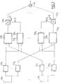
- Fig. 1 schematically represents a DS-CDMA system with K users.
- the data of a user k are spread in frequency by the corresponding signature in the module 100 k before being transmitted on a channel 110 k comprising P paths.
- the second characteristic mentioned above guarantees a low level of interference between two distinct users.
- the inter-correlation between two signatures is rarely zero. This is particularly the case in a so-called near-effect situation where a high power signal received from a user disturbs reception. a low power signal from another user.
- the sum of the interference of the different users small if taken in isolation, can have very disruptive effects for detection.
- FIG. 2 Such a receiving device is illustrated in FIG. 2.
- the device includes an array of antennas (200 1 ) ... (200 L ).
- Each channel trainer (220 i, k ) receives from an estimator (230 i, k ) of directions of arrival the estimated value ⁇ and i, k of the angle of arrival ⁇ i, k of the path i of the channel transmission k , which allows it to point its reception beam in the corresponding direction of arrival.
- channel formation (220 i, k ) consists in performing the calculation: and where x l, i, k and y i, k are respectively the inputs and the output of the channel trainer (220 i, k ).
- ⁇ and i, k is the angle of arrival defined with respect to the axis of the linear antenna array, d is the distance between two antennas of the array and ⁇ the length of the transmitted wave.
- the outputs of the P channel trainers are multiplied in (240 i, k ) by complex coefficients ⁇ i, k before being summed by a summator (250) to provide an output of MRC (Maximum Ratio Combining) type.
- the result of the combination is therefore:
- This reception device makes it possible to carry out both a formation of channels in the directions of the different routes and an MRC type combination as in a Rake filter.
- the proposed method presupposes, however, that the coefficients are determined attenuation, phase rotations and directions of arrival of all journeys of all users.
- the object of the invention is to provide a Rake receiver including a lane formation but not requiring the explicit calculation of the coefficients attenuation, phase rotations and directions of arrival of the different paths.
- the object of the invention defined by a reception method of a signal emitted by a transmitter and arriving on an antenna array after having propagated along a plurality of paths, comprising a decomposing filtering step each antenna signal into separate signals from the different paths, a step of combination linearly combining said separate signals by means of a game complex coefficients to provide a combined signal, the method forming a error signal between a set value of the transmitted signal and said signal combined, said set of complex coefficients being adapted so as to minimize the quadratic mean of the error signal.
- the transmitted signal comprising data modulated in the form of symbols
- the setpoint is a pilot symbol
- the transmitted signal comprising data modulated in the form of symbols
- the method further comprises a step estimation of the symbol transmitted from the combined signal, said value of setpoint then being an estimated value of the symbol transmitted.
- the transmitted signal comprising data modulated in the form of symbols
- the method further comprises a step estimation of the symbol transmitted from the combined signal, a step comprising demodulation of the estimated symbol into estimated data, deinterlacing and a channel decoding of said data, a step comprising a channel recoding of the decoded data followed by interleaving and modulation of said data to provide a re-estimated value of the transmitted symbol, the set value then being chosen equal to said re-estimated value.
- the set of complex coefficients is adapted according to a LMS or RLS algorithm.
- the object of the invention is also defined by a device for receiving a signal emitted by a transmitter, the device comprising an array of antennas and comprising means suitable for implementing the steps of the method described above.
- the basic idea of the invention is to get rid of an estimation of the directions of arrival, attenuation coefficients and phase rotations of the different paths in considering lane formation and combination of routes as one linear combination operation by complex coefficients, by initializing these coefficients to predetermined values and then adapting them so that minimize the mean square error between a setpoint signal and a signal observed at the end of the combination step.
- the antenna array is preferably a linear array consisting of L antennas regularly spaced by a distance d, but other types of array, in particular circular arrays, can also be envisaged.
- x l, i, k (t) [ ⁇ i, k (T). exp ( j ⁇ i, k )].
- the first term between square brackets represents the attenuation and the phase rotation undergone by the signal on the path i of channel k
- the second term between square brackets represents the phase shift due to the difference in path between the antenna l and the antenna 1 and n l, i, k (t) represents the additive white Gaussian noise at the antenna l, including thermal noise, multi-path interference and multi-user interference.
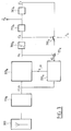
- Fig. 3 illustrates a receptor, performing channel formation and recombination in a single combination step by complex coefficients, such as proposed by the invention.
- the receiver shown is dedicated to receiving symbols transmitted on a k channel .
- the combination signal is subjected to a decision block (360 k ) providing in flexible or hard form the symbol s and k transmitted by the user k.
- a decision block 360 k
- the estim S and k symbol is then demodulated to provide one or more estimated data d and k .
- These data can then be subjected to a deinterlacing and channel decoding operation (370 k ) with soft or hard values (if, however, of course, the data have been interleaved and coded by a channel coding corresponding to the level of the user) .
- the invention proposes to adapt the coefficients b l, i, k so as to minimize a mean square error at the output of the complex combination module (320 k ).
- ⁇ k (T) q k (T) z k (T) where q k (t) is a set value corresponding to the observed signal z k (t).
- the estimated symbols s and k ( t ) are first demodulated and the data d and k obtained are deinterleaved, decoded by channel decoding (370 k ) then the data thus obtained are recoded by channel coding, re-interlaced and re-modulated (380 k ) to provide new estimated symbols, s and ' k ( t ), with better reliability than the initially estimated symbols, s and k ( t ).
- the decisions on the symbols taken in (360 k ) and those on the data taken in (370 k ) are flexible values, the symbols s and ' k ( t ) then being obtained by weighting of symbols of the constellation by their respective posterior probabilities.
- the recoding is not necessary if the data encoded at the output of the decoding is directly recovered.
- SOVA Soft Output Viterbi Algorithm
- the adaptation of the coefficients b l, i, k can be done with the pilot symbols only or either continue with the estimated symbols, before or after channel decoding, or even be carried out only thanks to the latter in the event of complete absence of symbols drivers.
- the starting configuration is thus a multi-path omni-directional configuration.
- the coefficients are modified so as to minimize the mean value E (
- the gradient ⁇ J k is estimated at time t by - ⁇ k ( t ).
- x * / k ( t ) hence taking into account (7):
- b k ( t 1) b k ( t ) + ⁇ k . ⁇ k ( t ).
- x * k ( t ) where the symbol * designates the conjugation operator.
- the coefficient ⁇ k is chosen lower than 1 / Tr ( R k ) where R k is the correlation matrix of x l, i, k ( t ) and Tr (.) Is the function trace.
- the adaptation of the coefficients b l, i, k can be ensured by means of the RLS (Recursive Least Square) algorithm as described, for example, in the article cited above or even by means an algorithm derived from the latter, preferably the Fast-RLS algorithm as described in the article by D. Falconer et al. entitled “Application of Fast Kalman estimation of adaptive equalization” published in IEEE Transactions on Communications, Vol. COM-5, Oct. '78, pages 1439-1446.
- RLS Recursive Least Square
- the RLS algorithm is based on a recurrence inversion of the correlation matrix ( R k ).
- K k (T) r k (T) T 1 + r k (T) T- x k (T)
- the adaptation will be carried out thanks to Fast-RLS algorithm.
- the invention has been described in the context of DS-CDMA, it can apply to other access modes provided that the channels of the different users and the different routes taken for a given channel can be separate at reception.
- the signals received are broadband, it is important to provide a temporal alignment of the signals having undergone propagation times different before the complex combination. If the separation of different users and journeys are carried out by batteries of filters at the antennas, the outputs of filters for the same route should be delayed so that they are aligned temporally. Time alignment can be achieved by FIFO buffers at mobile output pointers and finely adjusted by interpolation.
- receiver of FIG. 3 has been represented in the form of modules, however, it is clear to those skilled in the art that the operations represented by the different modules of FIG. 3 can be performed by a single processor programmed for this purpose or by a plurality of dedicated processors.
Landscapes
- Engineering & Computer Science (AREA)
- Computer Networks & Wireless Communication (AREA)
- Signal Processing (AREA)
- Physics & Mathematics (AREA)
- Mathematical Physics (AREA)
- Radio Transmission System (AREA)
- Noise Elimination (AREA)
- Cable Transmission Systems, Equalization Of Radio And Reduction Of Echo (AREA)
- Stereo-Broadcasting Methods (AREA)
- Variable-Direction Aerials And Aerial Arrays (AREA)
- Mobile Radio Communication Systems (AREA)
Applications Claiming Priority (2)
| Application Number | Priority Date | Filing Date | Title |
|---|---|---|---|
| FR0011683 | 2000-09-07 | ||
| FR0011683A FR2813729B1 (fr) | 2000-09-07 | 2000-09-07 | Recepteur cdma adaptatif uni-modulaire |
Publications (2)
| Publication Number | Publication Date |
|---|---|
| EP1187366A1 true EP1187366A1 (de) | 2002-03-13 |
| EP1187366B1 EP1187366B1 (de) | 2008-11-12 |
Family
ID=8854265
Family Applications (1)
| Application Number | Title | Priority Date | Filing Date |
|---|---|---|---|
| EP01402315A Expired - Lifetime EP1187366B1 (de) | 2000-09-07 | 2001-09-06 | Adaptiver uni-modularer CDMA-Empfänger |
Country Status (6)
| Country | Link |
|---|---|
| US (1) | US6850772B2 (de) |
| EP (1) | EP1187366B1 (de) |
| JP (1) | JP2002176382A (de) |
| AT (1) | ATE414354T1 (de) |
| DE (1) | DE60136517D1 (de) |
| FR (1) | FR2813729B1 (de) |
Families Citing this family (15)
| Publication number | Priority date | Publication date | Assignee | Title |
|---|---|---|---|---|
| FR2813728B1 (fr) * | 2000-09-07 | 2003-03-07 | Mitsubishi Electric Inf Tech | Recepteur cdma adaptatif bi-modulaire |
| US7161974B2 (en) * | 2001-09-10 | 2007-01-09 | Sasken Communication Technologies Ltd. | Method for 2D antenna rake combining in a code division multiplication access system |
| US7103098B2 (en) * | 2002-03-15 | 2006-09-05 | Intel Corporation | Adaptive receiver for multiplex/multi-access communications |
| US8005128B1 (en) * | 2003-09-23 | 2011-08-23 | Rambus Inc. | Methods for estimation and interference cancellation for signal processing |
| US7715508B2 (en) | 2005-11-15 | 2010-05-11 | Tensorcomm, Incorporated | Iterative interference cancellation using mixed feedback weights and stabilizing step sizes |
| WO2004040789A2 (en) * | 2002-10-29 | 2004-05-13 | Axiocom Inc. | Cascade filter receiver for ds-cdma communication systems |
| US7437135B2 (en) | 2003-10-30 | 2008-10-14 | Interdigital Technology Corporation | Joint channel equalizer interference canceller advanced receiver |
| US7400692B2 (en) * | 2004-01-14 | 2008-07-15 | Interdigital Technology Corporation | Telescoping window based equalization |
| US7826516B2 (en) | 2005-11-15 | 2010-11-02 | Rambus Inc. | Iterative interference canceller for wireless multiple-access systems with multiple receive antennas |
| US7711075B2 (en) | 2005-11-15 | 2010-05-04 | Tensorcomm Incorporated | Iterative interference cancellation using mixed feedback weights and stabilizing step sizes |
| US7991088B2 (en) | 2005-11-15 | 2011-08-02 | Tommy Guess | Iterative interference cancellation using mixed feedback weights and stabilizing step sizes |
| US7702048B2 (en) * | 2005-11-15 | 2010-04-20 | Tensorcomm, Incorporated | Iterative interference cancellation using mixed feedback weights and stabilizing step sizes |
| US20070110135A1 (en) * | 2005-11-15 | 2007-05-17 | Tommy Guess | Iterative interference cancellation for MIMO-OFDM receivers |
| US7623602B2 (en) * | 2005-11-15 | 2009-11-24 | Tensorcomm, Inc. | Iterative interference canceller for wireless multiple-access systems employing closed loop transmit diversity |
| KR102734613B1 (ko) * | 2020-04-17 | 2024-11-27 | 삼성전자주식회사 | Mimo를 지원하는 무선 통신 시스템에서 채널 추정 방법 및 장치 |
Family Cites Families (3)
| Publication number | Priority date | Publication date | Assignee | Title |
|---|---|---|---|---|
| US5623485A (en) * | 1995-02-21 | 1997-04-22 | Lucent Technologies Inc. | Dual mode code division multiple access communication system and method |
| ZA965340B (en) * | 1995-06-30 | 1997-01-27 | Interdigital Tech Corp | Code division multiple access (cdma) communication system |
| US6603804B1 (en) * | 1999-10-01 | 2003-08-05 | Agere Systems Inc. | Upsampling filter having one-bit multipliers for multiple spread-data streams |
-
2000
- 2000-09-07 FR FR0011683A patent/FR2813729B1/fr not_active Expired - Fee Related
-
2001
- 2001-08-22 US US09/933,824 patent/US6850772B2/en not_active Expired - Fee Related
- 2001-09-06 DE DE60136517T patent/DE60136517D1/de not_active Expired - Fee Related
- 2001-09-06 EP EP01402315A patent/EP1187366B1/de not_active Expired - Lifetime
- 2001-09-06 AT AT01402315T patent/ATE414354T1/de not_active IP Right Cessation
- 2001-09-07 JP JP2001271471A patent/JP2002176382A/ja not_active Withdrawn
Non-Patent Citations (2)
| Title |
|---|
| MATSUOKA H ET AL: "PATH DIVERSITY USING AN ADAPTIVE ARRAY WITH DIRECTIONAL ANTENNAS FOR HIGH BIT RATE MOBILE COMMUNICATION SYSTEMS", SYDNEY, NOV. 8 - 12, 1998,NEW YORK, NY: IEEE,US, 8 November 1998 (1998-11-08), pages 171 - 176, XP000894297, ISBN: 0-7803-4985-7 * |
| TANAKA S ET AL: "EXPERIMENT ON COHERENT ADAPTIVE ANTENNA ARRAY FOR WIDEBAND DS-CDMA MOBILE RADIO", ELECTRONICS LETTERS,IEE STEVENAGE,GB, vol. 34, no. 23, 12 November 1998 (1998-11-12), pages 2204 - 2205, XP000871225, ISSN: 0013-5194 * |
Also Published As
| Publication number | Publication date |
|---|---|
| US20020045462A1 (en) | 2002-04-18 |
| ATE414354T1 (de) | 2008-11-15 |
| JP2002176382A (ja) | 2002-06-21 |
| FR2813729A1 (fr) | 2002-03-08 |
| DE60136517D1 (de) | 2008-12-24 |
| FR2813729B1 (fr) | 2004-11-05 |
| US6850772B2 (en) | 2005-02-01 |
| EP1187366B1 (de) | 2008-11-12 |
Similar Documents
| Publication | Publication Date | Title |
|---|---|---|
| EP1189361B1 (de) | Verfahren zur Mehrbenutzerdetektion | |
| EP0735702B1 (de) | Verfahren und Vorrichtung zum Diversity-Empfang einer Basisstation in einem Mobilkommunikationssystem | |
| EP0867079B1 (de) | Verfahren und anordnung zur entzerrung von mehrfachantennensignalen für mehrfachelementempfang in gegenwart von störungen und mehrwegausbreitungen | |
| EP1187366B1 (de) | Adaptiver uni-modularer CDMA-Empfänger | |
| EP1255362A1 (de) | Verfahren und Vorrichtung zum Empfang eines Signals | |
| FR2715523A1 (fr) | Récepteur et procédé de réception pour un système d'accès multiple par répartition par code. | |
| EP1185004A1 (de) | Verfahren zum gemeinsamen Einfallswinkel- und Kanalschätzung | |
| EP3343784A1 (de) | Verfahren zur anwendung von entstörungsmassnahmen durch räumliche oder räumlich-zeitliche filterung in einem mehrweg-empfänger | |
| EP1260071B1 (de) | Verfahren und vorrichtung für kanalschäztung | |
| EP1184997A1 (de) | Verfahren zur Mehrbenutzerdetektion | |
| EP1105975B1 (de) | Iterativer rake-empfänger und entsprechendes empfangsverfahren | |
| EP0669729B1 (de) | Verfahren zur Durchführung von einer mehrkanalen Entzerrung in einem Rundfunkempfänger bei Störungen und Mehrwegeausbreitung | |
| EP0820157B1 (de) | Verfahren zur digitalen Differenzialdemodulation | |
| FR2813728A1 (fr) | Recepteur cdma adaptatif bi-modulaire | |
| EP1265374B1 (de) | Verfahren und Vorrichtung zur Signalverarbeitung in einem Spreizspektrum Funkkommunikationsempfänger | |
| EP1283605A1 (de) | Verfahren zur Erhöhung der Datenrate in einem Kommunikationssystem mit N Sendern und M Empfängern | |
| FR2815508A1 (fr) | Methode d'estimation de canal descendant | |
| EP1623514B1 (de) | Spreizspektrummodulator und -demodulator | |
| FR2882479A1 (fr) | Procede et dispositif de synchronisation de liaisons rectilignes ou quasi-rectilignes en presence d'interferences | |
| FR2802043A1 (fr) | Dispositifs d'estimation de canal radio et de demodulation | |
| EP1299969A1 (de) | Datenübertragungssystem und -verfahren mit raum-zeit-kodierung | |
| FR2735635A1 (fr) | Procede permettant une egalisation multicapteur dans un recepteur radioelectrique, en presence d'interferences et de multitrajets de propagation | |
| Ait Fares et al. | Sequential Blind Beamforming for Wireless Multipath Communications in Confined Areas |
Legal Events
| Date | Code | Title | Description |
|---|---|---|---|
| PUAI | Public reference made under article 153(3) epc to a published international application that has entered the european phase |
Free format text: ORIGINAL CODE: 0009012 |
|
| AK | Designated contracting states |
Kind code of ref document: A1 Designated state(s): AT BE CH CY DE DK ES FI FR GB GR IE IT LI LU MC NL PT SE TR |
|
| AX | Request for extension of the european patent |
Free format text: AL;LT;LV;MK;RO;SI |
|
| 17P | Request for examination filed |
Effective date: 20020613 |
|
| AKX | Designation fees paid |
Free format text: AT BE CH CY DE DK ES FI FR GB GR IE IT LI LU MC NL PT SE TR |
|
| RAP1 | Party data changed (applicant data changed or rights of an application transferred) |
Owner name: MITSUBISHI ELECTRIC INFORMATION TECHNOLOGY CENTRE |
|
| 17Q | First examination report despatched |
Effective date: 20061106 |
|
| GRAP | Despatch of communication of intention to grant a patent |
Free format text: ORIGINAL CODE: EPIDOSNIGR1 |
|
| GRAS | Grant fee paid |
Free format text: ORIGINAL CODE: EPIDOSNIGR3 |
|
| GRAA | (expected) grant |
Free format text: ORIGINAL CODE: 0009210 |
|
| AK | Designated contracting states |
Kind code of ref document: B1 Designated state(s): AT BE CH CY DE DK ES FI FR GB GR IE IT LI LU MC NL PT SE TR |
|
| REG | Reference to a national code |
Ref country code: GB Ref legal event code: FG4D Free format text: NOT ENGLISH |
|
| REG | Reference to a national code |
Ref country code: CH Ref legal event code: EP |
|
| REG | Reference to a national code |
Ref country code: IE Ref legal event code: FG4D Free format text: LANGUAGE OF EP DOCUMENT: FRENCH |
|
| REF | Corresponds to: |
Ref document number: 60136517 Country of ref document: DE Date of ref document: 20081224 Kind code of ref document: P |
|
| PG25 | Lapsed in a contracting state [announced via postgrant information from national office to epo] |
Ref country code: ES Free format text: LAPSE BECAUSE OF FAILURE TO SUBMIT A TRANSLATION OF THE DESCRIPTION OR TO PAY THE FEE WITHIN THE PRESCRIBED TIME-LIMIT Effective date: 20090223 Ref country code: AT Free format text: LAPSE BECAUSE OF FAILURE TO SUBMIT A TRANSLATION OF THE DESCRIPTION OR TO PAY THE FEE WITHIN THE PRESCRIBED TIME-LIMIT Effective date: 20081112 |
|
| NLV1 | Nl: lapsed or annulled due to failure to fulfill the requirements of art. 29p and 29m of the patents act | ||
| PG25 | Lapsed in a contracting state [announced via postgrant information from national office to epo] |
Ref country code: FI Free format text: LAPSE BECAUSE OF FAILURE TO SUBMIT A TRANSLATION OF THE DESCRIPTION OR TO PAY THE FEE WITHIN THE PRESCRIBED TIME-LIMIT Effective date: 20081112 Ref country code: NL Free format text: LAPSE BECAUSE OF FAILURE TO SUBMIT A TRANSLATION OF THE DESCRIPTION OR TO PAY THE FEE WITHIN THE PRESCRIBED TIME-LIMIT Effective date: 20081112 |
|
| REG | Reference to a national code |
Ref country code: IE Ref legal event code: FD4D |
|
| PG25 | Lapsed in a contracting state [announced via postgrant information from national office to epo] |
Ref country code: DK Free format text: LAPSE BECAUSE OF FAILURE TO SUBMIT A TRANSLATION OF THE DESCRIPTION OR TO PAY THE FEE WITHIN THE PRESCRIBED TIME-LIMIT Effective date: 20081112 Ref country code: IE Free format text: LAPSE BECAUSE OF FAILURE TO SUBMIT A TRANSLATION OF THE DESCRIPTION OR TO PAY THE FEE WITHIN THE PRESCRIBED TIME-LIMIT Effective date: 20081112 |
|
| PG25 | Lapsed in a contracting state [announced via postgrant information from national office to epo] |
Ref country code: PT Free format text: LAPSE BECAUSE OF FAILURE TO SUBMIT A TRANSLATION OF THE DESCRIPTION OR TO PAY THE FEE WITHIN THE PRESCRIBED TIME-LIMIT Effective date: 20090413 Ref country code: SE Free format text: LAPSE BECAUSE OF FAILURE TO SUBMIT A TRANSLATION OF THE DESCRIPTION OR TO PAY THE FEE WITHIN THE PRESCRIBED TIME-LIMIT Effective date: 20090212 |
|
| PLBE | No opposition filed within time limit |
Free format text: ORIGINAL CODE: 0009261 |
|
| STAA | Information on the status of an ep patent application or granted ep patent |
Free format text: STATUS: NO OPPOSITION FILED WITHIN TIME LIMIT |
|
| 26N | No opposition filed |
Effective date: 20090813 |
|
| BERE | Be: lapsed |
Owner name: MITSUBISHI ELECTRIC INFORMATION TECHNOLOGY CENTRE Effective date: 20090930 |
|
| PG25 | Lapsed in a contracting state [announced via postgrant information from national office to epo] |
Ref country code: MC Free format text: LAPSE BECAUSE OF NON-PAYMENT OF DUE FEES Effective date: 20090930 |
|
| REG | Reference to a national code |
Ref country code: CH Ref legal event code: PL |
|
| GBPC | Gb: european patent ceased through non-payment of renewal fee |
Effective date: 20090906 |
|
| REG | Reference to a national code |
Ref country code: FR Ref legal event code: ST Effective date: 20100531 |
|
| PG25 | Lapsed in a contracting state [announced via postgrant information from national office to epo] |
Ref country code: FR Free format text: LAPSE BECAUSE OF NON-PAYMENT OF DUE FEES Effective date: 20090930 Ref country code: DE Free format text: LAPSE BECAUSE OF NON-PAYMENT OF DUE FEES Effective date: 20100401 |
|
| PG25 | Lapsed in a contracting state [announced via postgrant information from national office to epo] |
Ref country code: BE Free format text: LAPSE BECAUSE OF NON-PAYMENT OF DUE FEES Effective date: 20090930 |
|
| PG25 | Lapsed in a contracting state [announced via postgrant information from national office to epo] |
Ref country code: GR Free format text: LAPSE BECAUSE OF FAILURE TO SUBMIT A TRANSLATION OF THE DESCRIPTION OR TO PAY THE FEE WITHIN THE PRESCRIBED TIME-LIMIT Effective date: 20090213 Ref country code: CH Free format text: LAPSE BECAUSE OF NON-PAYMENT OF DUE FEES Effective date: 20090930 Ref country code: LI Free format text: LAPSE BECAUSE OF NON-PAYMENT OF DUE FEES Effective date: 20090930 |
|
| PG25 | Lapsed in a contracting state [announced via postgrant information from national office to epo] |
Ref country code: GB Free format text: LAPSE BECAUSE OF NON-PAYMENT OF DUE FEES Effective date: 20090906 |
|
| PG25 | Lapsed in a contracting state [announced via postgrant information from national office to epo] |
Ref country code: IT Free format text: LAPSE BECAUSE OF FAILURE TO SUBMIT A TRANSLATION OF THE DESCRIPTION OR TO PAY THE FEE WITHIN THE PRESCRIBED TIME-LIMIT Effective date: 20081112 |
|
| PG25 | Lapsed in a contracting state [announced via postgrant information from national office to epo] |
Ref country code: LU Free format text: LAPSE BECAUSE OF NON-PAYMENT OF DUE FEES Effective date: 20090906 |
|
| PG25 | Lapsed in a contracting state [announced via postgrant information from national office to epo] |
Ref country code: TR Free format text: LAPSE BECAUSE OF FAILURE TO SUBMIT A TRANSLATION OF THE DESCRIPTION OR TO PAY THE FEE WITHIN THE PRESCRIBED TIME-LIMIT Effective date: 20081112 |
|
| PG25 | Lapsed in a contracting state [announced via postgrant information from national office to epo] |
Ref country code: CY Free format text: LAPSE BECAUSE OF FAILURE TO SUBMIT A TRANSLATION OF THE DESCRIPTION OR TO PAY THE FEE WITHIN THE PRESCRIBED TIME-LIMIT Effective date: 20081112 |