EP1187366B1 - Adaptiver uni-modularer CDMA-Empfänger - Google Patents
Adaptiver uni-modularer CDMA-Empfänger Download PDFInfo
- Publication number
- EP1187366B1 EP1187366B1 EP01402315A EP01402315A EP1187366B1 EP 1187366 B1 EP1187366 B1 EP 1187366B1 EP 01402315 A EP01402315 A EP 01402315A EP 01402315 A EP01402315 A EP 01402315A EP 1187366 B1 EP1187366 B1 EP 1187366B1
- Authority
- EP
- European Patent Office
- Prior art keywords
- signal
- coefficients
- transmitted
- paths
- symbol
- Prior art date
- Legal status (The legal status is an assumption and is not a legal conclusion. Google has not performed a legal analysis and makes no representation as to the accuracy of the status listed.)
- Expired - Lifetime
Links
- 230000003044 adaptive effect Effects 0.000 title abstract description 4
- 238000000034 method Methods 0.000 claims abstract description 29
- 238000001914 filtration Methods 0.000 claims description 8
- 230000000644 propagated effect Effects 0.000 claims description 4
- 230000005540 biological transmission Effects 0.000 abstract description 7
- 230000006978 adaptation Effects 0.000 description 10
- 230000015572 biosynthetic process Effects 0.000 description 10
- 230000000875 corresponding effect Effects 0.000 description 5
- 239000011159 matrix material Substances 0.000 description 5
- 238000000926 separation method Methods 0.000 description 5
- 238000004891 communication Methods 0.000 description 4
- 238000001514 detection method Methods 0.000 description 4
- 230000000694 effects Effects 0.000 description 3
- 239000013598 vector Substances 0.000 description 3
- 108010003272 Hyaluronate lyase Proteins 0.000 description 2
- 238000003491 array Methods 0.000 description 2
- 238000004364 calculation method Methods 0.000 description 2
- 230000001427 coherent effect Effects 0.000 description 2
- 230000008030 elimination Effects 0.000 description 2
- 238000003379 elimination reaction Methods 0.000 description 2
- 238000012552 review Methods 0.000 description 2
- 238000007476 Maximum Likelihood Methods 0.000 description 1
- 239000000654 additive Substances 0.000 description 1
- 230000000996 additive effect Effects 0.000 description 1
- 239000000872 buffer Substances 0.000 description 1
- 230000001413 cellular effect Effects 0.000 description 1
- 230000021615 conjugation Effects 0.000 description 1
- 230000002596 correlated effect Effects 0.000 description 1
- 230000007547 defect Effects 0.000 description 1
- 230000003111 delayed effect Effects 0.000 description 1
- 238000002474 experimental method Methods 0.000 description 1
- 238000010295 mobile communication Methods 0.000 description 1
- 230000010363 phase shift Effects 0.000 description 1
- 238000012545 processing Methods 0.000 description 1
- 230000001902 propagating effect Effects 0.000 description 1
- 230000006798 recombination Effects 0.000 description 1
- 238000005215 recombination Methods 0.000 description 1
- 230000002123 temporal effect Effects 0.000 description 1
Images

Classifications
-
- H—ELECTRICITY
- H04—ELECTRIC COMMUNICATION TECHNIQUE
- H04B—TRANSMISSION
- H04B1/00—Details of transmission systems, not covered by a single one of groups H04B3/00 - H04B13/00; Details of transmission systems not characterised by the medium used for transmission
- H04B1/69—Spread spectrum techniques
- H04B1/707—Spread spectrum techniques using direct sequence modulation
- H04B1/7097—Interference-related aspects
- H04B1/711—Interference-related aspects the interference being multi-path interference
- H04B1/7115—Constructive combining of multi-path signals, i.e. RAKE receivers
-
- H—ELECTRICITY
- H04—ELECTRIC COMMUNICATION TECHNIQUE
- H04B—TRANSMISSION
- H04B7/00—Radio transmission systems, i.e. using radiation field
- H04B7/02—Diversity systems; Multi-antenna system, i.e. transmission or reception using multiple antennas
- H04B7/04—Diversity systems; Multi-antenna system, i.e. transmission or reception using multiple antennas using two or more spaced independent antennas
- H04B7/08—Diversity systems; Multi-antenna system, i.e. transmission or reception using multiple antennas using two or more spaced independent antennas at the receiving station
- H04B7/0837—Diversity systems; Multi-antenna system, i.e. transmission or reception using multiple antennas using two or more spaced independent antennas at the receiving station using pre-detection combining
- H04B7/0842—Weighted combining
- H04B7/0848—Joint weighting
- H04B7/0851—Joint weighting using training sequences or error signal
-
- H—ELECTRICITY
- H04—ELECTRIC COMMUNICATION TECHNIQUE
- H04B—TRANSMISSION
- H04B7/00—Radio transmission systems, i.e. using radiation field
- H04B7/02—Diversity systems; Multi-antenna system, i.e. transmission or reception using multiple antennas
- H04B7/04—Diversity systems; Multi-antenna system, i.e. transmission or reception using multiple antennas using two or more spaced independent antennas
- H04B7/08—Diversity systems; Multi-antenna system, i.e. transmission or reception using multiple antennas using two or more spaced independent antennas at the receiving station
- H04B7/0837—Diversity systems; Multi-antenna system, i.e. transmission or reception using multiple antennas using two or more spaced independent antennas at the receiving station using pre-detection combining
- H04B7/0842—Weighted combining
- H04B7/0848—Joint weighting
- H04B7/0854—Joint weighting using error minimizing algorithms, e.g. minimum mean squared error [MMSE], "cross-correlation" or matrix inversion
Definitions
- the present invention generally relates to a method and a receiving device operating in Code Division Multiple Access (CDMA or Code Division Multiple Access) mode. More specifically, when the propagation of the signal between the transmitter of a user and a network of reception antennas takes place according to multiple paths, the present invention makes it possible to estimate the signal transmitted by the transmitter from the signals of antennas.
- CDMA Code Division Multiple Access
- the propagation of the signal from a transmitter to a receiver can be done by multipath, each path being characterized by a delay, a direction of arrival, an attenuation and a phase rotation.
- the signals of the different mobile terminals to the base station are transmitted by different channels.
- Each transmission channel includes a plurality of paths to the base station, each path being characterized by a delay, an arrival direction, an attenuation, and a phase rotation.
- Some systems face high interference.
- the different users transmit at the same time in the same frequency band and the transmitted signals necessarily interfere with each other.
- the separation of the different users is achieved by multiplying each symbol of the user by a spreading sequence of its own, still called for this reason the user's signature, the different signatures being ideally chosen orthogonal. Since the chip rate is greater than the frequency of the symbols, the signal transmitted by each user is distributed (or spread) in the frequency space.
- the separation of the signal of a user is carried out thanks to a filtering adapted to the corresponding signature. This filtering is also called "de-spreading".
- the ratio of the band occupied by the spread signal to the band occupied by the information signal is called the spreading factor.
- the signatures employed must have good correlation properties, namely a very pronounced peak of autocorrelation and low inter-correlation values.
- the first of these two features allows synchronization of the received sequence. It is very useful when the transmission channel of a user has several propagation paths. Indeed, each path can then be isolated through a filter adapted to the signature and the delay of the path. The diversity of propagation within the channel can be used to increase the signal-to-noise ratio on reception. To do this, a bank of suitable filters separating the different paths is used and the outputs are combined. The most common combination is the MRC ( Maximum Ratio Combining ), which consists in multiplying the output signal of each adapted filter by the conjugate of the complex multiplicative coefficient introduced by the channel on the path concerned. The resulting filtering operation is a filtering adapted to the equivalent filter of the channel.
- MRC Maximum Ratio Combining
- the receiver thus constituted is called rake receiver or Rake receiver.
- the Fig. 1 schematically represents a DS-CDMA system with K users.
- the data of a user k are frequency-spread by the corresponding signature in the module 100 k before being transmitted on a channel 110 k having P paths.
- the channels 1 to K are identical while they differ in the uplink (mobile terminal links to the base station).
- the first case can, from this point of view, be considered as a particular case of the second.
- the second feature stated above ensures a low level of interference between two different users.
- the inter-correlation between two signatures is rarely zero. This is particularly the case in the so-called " near-far effect" situation where a high power signal received from a user disturbs the reception. a low power signal from another user.
- the sum of the interference of different users, low if taken alone can have very disruptive effects for detection.
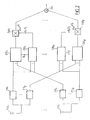
- Such a reception device is illustrated in Fig. 2 .
- the device comprises an antenna array (200 1 ) ... (200 L ).
- Each channel trainer (220 i, k ) receives from an estimator (230 i, k ) of arrival directions the estimated value ⁇ i, k of the arrival angle ⁇ i, k of the path i of the channel of transmission k , which allows it to point its reception beam in the corresponding direction of arrival.
- ⁇ i, k is the angle of arrival defined with respect to the axis of the linear antenna array
- d is the distance between two antennas of the network
- ⁇ the length of the transmitted wave.
- the outputs of the P trainers of channels are multiplied in (240 i, k ) by complex coefficients ⁇ i, k before being summed by an adder (250) to provide an output of the type MRC (Maximum Ratio Combining).
- This receiving device makes it possible to perform both channel formation in the directions of the different paths and a combination of the MRC type as in a Rake filter.
- the proposed method assumes, however, that the attenuation coefficients, phase rotations and arrival directions of all the paths of all users are determined.
- Tanaka S publication entitled “Experiment on coherent adaptive antenna array for DS-CDMA mobile radio” discloses a method of receiving a signal transmitted by a transmitter and arriving on an antenna array after propagating in a plurality of paths, in which each antenna signal is broken down into separate signals from the different paths, and the separated signals are combined using a coherent Rake combiner.
- the object of the invention is to propose a Rake receiver including channel formation but not requiring the explicit calculation of the attenuation coefficients, phase rotations and arrival directions of the different paths.
- the object of the invention defined by a method of receiving a signal transmitted by a transmitter and arriving on an antenna array after being propagated along a plurality of paths, comprising a filtering step decomposing each antenna signal into separate signals from the different paths, a combining step linearly combining said separated signals using a set of complex coefficients to provide a combined signal the method forming an error signal between a set value of the transmitted signal and said combined signal, said set of complex coefficients being adapted to minimize the root mean square of the error signal.
- the transmitted signal comprising data modulated in the form of symbols
- the set value is a pilot symbol
- the transmitted signal comprising data modulated in the form of symbols
- the method further comprises a step of estimating the transmitted symbol from the combined signal, said set value then being an estimated value of the transmitted symbol.
- the transmitted signal comprising data modulated in the form of symbols
- the method further comprises a step of estimating the symbol transmitted from the combined signal, a step comprising a demodulation of the estimated symbol into estimated data. , deinterleaving and channel decoding said data, a step comprising channel recoding of the decoded data followed by interleaving and modulating said data to provide a reestimated value of the transmitted symbol, the set value then being chosen equal to said reestimated value .
- the complex coefficient set is adapted according to an LMS or RLS type algorithm.
- the object of the invention is also defined by a device for receiving a signal emitted by a transmitter, the device comprising an antenna array and comprising means adapted to the implementation of the steps of the method set out above. .
- the basic idea of the invention is to overcome an estimation of the arrival directions, attenuation coefficients and phase rotations of the different paths by considering the formation of the path and the combination of paths as a single operation. of linear combination by complex coefficients, by initializing these coefficients to predetermined values and then adapting them so as to minimize the mean squared error between a setpoint signal and a signal observed at the output of the combination step.
- the antenna array is preferably a linear array consisting of L antennas regularly spaced a distance d but other types of networks, including circular networks, can also be envisaged.
- x l , i , k t ⁇ i , k t . exp j ⁇ ⁇ i , k . exp j ⁇ 2 ⁇ ⁇ d / ⁇ ⁇ cos ⁇ i , k t . l - 1 . s k t + not l , i , k t
- brackets represent the attenuation and phase rotation experienced by the signal on the path i of the channel k
- the second term between brackets represents the phase shift due to the difference in path between the antenna l and the antenna 1 and nl, i , k (t) is Gaussian additive white noise at the antenna l, including thermal noise, multipath interference and multiuser interference.
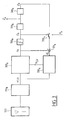
- the Fig. 3 illustrates a receiver, performing channel formation and recombination in a single combination step by complex coefficients, as proposed by the invention.
- the receiver shown is dedicated to the reception of transmitted symbols on a channel k.
- the system comprises L antennas represented schematically by the block (300 k ). Each of the L antenna signals is then correlated by a battery of P adapted filters where P is the number of propagation paths of the channel, each filter being adapted to a path i .
- P adapted filters being transmitted to a module linearly combining these output signals with complex coefficients bl, i , k represented by the block (320 k ) to provide a combination signal z k .
- the combination signal is subjected to a decision block (360 k ) providing in flexible or hard form the symbol ⁇ k transmitted by the user k.
- flexible decision we mean here the result of a weighting of symbols by their probabilities to respective posteriori.
- the estimated symbol ⁇ k is then demodulated to provide one or more estimated data d k .
- This data can then be subjected to a flexible or hard-soft channel de-interleaving and decoding operation (370 k ) (though, of course, the data has been interleaved and coded by user-level channel coding) .
- the invention proposes to adapt the coefficients b l, i , k so as to minimize an average square error at the output of the complex combination module (320 k ).
- the estimated symbols ⁇ k ( t ) are first demodulated and the data d k obtained are deinterleaved, decoded by channel decoding (370 k ) and then the data thus obtained are coded by channel coding, re-interleaved and remodulated ( 380 k ) to provide new estimated symbols, ⁇ ' k ( t ), with better reliability than the estimated symbols, ⁇ k ( t ).
- the decisions on the symbols taken in (360 k ) and those on the data taken in (370 k ) are soft values, the symbols ⁇ ' k ( t ) being then obtained by weighting symbols of the constellation by their respective posterior probabilities.
- recoding is not necessary if the data encoded at the output of the decoding is recovered directly.
- SOVA Soft Output Viterbi Algorithm
- the adaptation of the coefficients b l, i , k can be done with the pilot symbols only either continue with the estimated symbols, before or after channel decoding, or be carried out only with the latter in case of complete absence of symbols drivers.
- the initial configuration is thus an omni-directional multi-path configuration.
- the coefficients are modified so as to minimize the average value E (
- the coefficient adaptation algorithm is based on minimizing the mean squared error.
- Many algorithms have been proposed for this purpose in the literature and a description of the main ones can be found in the review article of LC Godara entitled "Application of Antenna Arrays to Mobile Communications, Part II: Beam-Forming and Direction-of-Arrival Considerations" in Proceedings of the IEEE, Vol. 85, No. 8, August '97, pages 1195-1245 .
- the coefficient ⁇ k is chosen less than 1 / Tr ( R k ) where R k is the correlation matrix of x l , i, k ( t ) and Tr (.) Is the function trace.
- the adaptation of the coefficients b l, i , k can be ensured by means of the RLS algorithm (Recursive Least Square) as described, for example, in the article cited above or by means of an algorithm derived from the latter, preferably the Fast-RLS algorithm as described in the article of D. Falconer et al. entitled “Application of Fast Kalman estimation of adaptive equalization” published in IEEE Transactions on Communications, Vol. COM-5, Oct. '78, pp. 1439-1446 .
- RLS algorithm Recursive Least Square
- the RLS algorithm is based on a recursive inversion of the correlation matrix ( R k ).
- a forgetting factor will be included in equations (12) and (14) so that only the contributions of the most recent input vectors will be taken into account in the estimation of the correlation matrix.
- the adaptation will be carried out using the Fast-RLS algorithm.
- the invention has been exposed in the context of DS-CDMA, it can be applied to other modes of access provided that the channels of the different users and the different paths taken for a given channel can be separated. at the reception.
- the received signals are broadband, it is important to provide a temporal alignment of the signals having undergone different propagation times before the complex combination. If the separation of the different users and paths is carried out by filter banks at the antennas, the outputs of the filters relating to the same path must be delayed so as to be temporally aligned. Time alignment can be achieved by FIFO buffers with moving output pointers and finely tuned by interpolation.
- the receiver of the Fig. 3 has been represented in the form of modules, however, it is clear to those skilled in the art that the operations represented by the various modules of the Fig. 3 can be performed by a single processor programmed for this purpose or by a plurality of dedicated processors.
Landscapes
- Engineering & Computer Science (AREA)
- Computer Networks & Wireless Communication (AREA)
- Signal Processing (AREA)
- Physics & Mathematics (AREA)
- Mathematical Physics (AREA)
- Radio Transmission System (AREA)
- Noise Elimination (AREA)
- Cable Transmission Systems, Equalization Of Radio And Reduction Of Echo (AREA)
- Stereo-Broadcasting Methods (AREA)
- Variable-Direction Aerials And Aerial Arrays (AREA)
- Mobile Radio Communication Systems (AREA)
Claims (9)
- Verfahren zum Empfang eines durch einen Sender (k) gesendeten und auf einem Antennennetz (300) eintreffenden Signals, nachdem es sich auf mehreren Wegen (i) ausgebreitet hat, das einen Filterungsschritt (310k), der jedes Antennensignal in getrennte, aus den unterschiedlichen Wegen hervorgehende Signale (xℓ,i,k) zerlegt, und einen Verknüpfungsschritt (320k), der die getrennten Signale mittels eines Satzes von komplexen Koeffizienten linear verknüpft, um ein verknüpftes Signal (zk) zu liefern, umfasst, wobei das Verfahren dadurch gekennzeichnet ist, dass ein Fehlersignal (ε k) zwischen einem Sollwert (q k) des übertragenen Signals und dem verknüpften Signal gebildet (331k) wird und dass der Satz von komplexen Koeffizienten derart angepasst (330k) wird, dass der quadratische Mittelwert des Fehlersignals minimiert wird.
- Empfangsverfahren nach Anspruch 1, dadurch gekennzeichnet, dass das gesendete Signal in Form von Symbolen modulierte Daten umfasst, wobei der Sollwert ein Pilotsymbol (p k) ist.
- Empfangsverfahren nach Anspruch 1, dadurch gekennzeichnet, dass das gesendete Signal in Form von Symbolen modulierte Daten umfasst, wobei das Verfahren ferner einen Schritt (360k) zur Schätzung des ausgehend vom verknüpften Signal (zk) übertragenen Symbols umfasst, wobei der Sollwert dann ein geschätzter Wert (ŝk) des übertragenen Symbols ist.
- Empfangsverfahren nach Anspruch 1, dadurch gekennzeichnet, dass das gesendete Signal in Form von Symbolen modulierte Daten umfasst, wobei das Verfahren ferner einen Schritt (360k) zur Schätzung des ausgehend vom verknüpften Signal (zk) übertragenen Symbols, einen Schritt (370k), der eine Demodulation des geschätzten Symbols in geschätzte Daten, eine Entschachtelung und eine Kanaldecodierung der Daten (d̂ k) umfasst, und einen Schritt (380k) umfasst, der eine Kanalneucodierung der decodierten Daten umfasst, der eine Verschachtelung und eine Modulation der Daten folgt, um einen neu geschätzten Wert (ŝ k) des übertragenen Symbols zu liefern, wobei der Sollwert dann gleich dem neu geschätzten Wert gewählt wird.
- Empfangsverfahren nach einem der vorhergehenden Ansprüche, dadurch gekennzeichnet, dass der Satz von komplexen Koeffizienten gemäß einem Algorithmus des Typs LMS angepasst wird.
- Empfangsverfahren nach einem der Ansprüche 1 bis 4, dadurch gekennzeichnet, dass der Satz von komplexen Koeffizienten gemäß einem Algorithmus des Typs RLS angepasst wird.
- Empfangsverfahren nach Anspruch 5 oder 6, dadurch gekennzeichnet, dass der Satz von Koeffizienten mit den Werten bℓ,i,k(0)=b. δ (ℓ-ℓ0), ∀i initialisiert wird, wo δ das Dirac-Symbol ist, ℓ0 eine Antennennummer und b ein komplexer Koeffizient ist.
- Empfangsverfahren nach Anspruch 5 oder 6, dadurch gekennzeichnet, dass der Satz von Koeffizienten mittels einer vorherigen Schätzung der Empfangsrichtungen der unterschiedlichen Wege sowie Dämpfungskoeffizienten und Phasendrehungen, die das Signal entlang der Wege beeinträchtigen, initialisiert wird.
- Vorrichtung zum Empfang eines durch einen Sender (k) gesendeten und auf einem Antennennetz (300) eintreffenden Signals, nachdem es sich auf mehreren Wegen (i) ausgebreitet hat, wobei die Empfangsvorrichtung Filterungsmittel (310k), die jedes Antennensignal in getrennte, aus den unterschiedlichen Wegen hervorgehende Signale (xl,i,k) zerlegen, und Verknüpfungsmittel (320k), die die getrennten Signale mittels eines Satzes von komplexen Koeffizienten linear verknüpfen, um ein verknüpftes Signal (zk) zu liefern, umfasst, wobei die Empfangsvorrichtung dadurch gekennzeichnet ist, dass sie Mittel zur Bildung (331k) eines Fehlersignals (ε k) zwischen einem Sollwert (qk) des übertragenen Signals und dem verknüpften Signal umfasst und dass der Satz von komplexen Koeffizienten derart angepasst (330k) wird, dass der quadratische Mittelwert des Fehlersignals minimiert wird.
Applications Claiming Priority (2)
| Application Number | Priority Date | Filing Date | Title |
|---|---|---|---|
| FR0011683 | 2000-09-07 | ||
| FR0011683A FR2813729B1 (fr) | 2000-09-07 | 2000-09-07 | Recepteur cdma adaptatif uni-modulaire |
Publications (2)
| Publication Number | Publication Date |
|---|---|
| EP1187366A1 EP1187366A1 (de) | 2002-03-13 |
| EP1187366B1 true EP1187366B1 (de) | 2008-11-12 |
Family
ID=8854265
Family Applications (1)
| Application Number | Title | Priority Date | Filing Date |
|---|---|---|---|
| EP01402315A Expired - Lifetime EP1187366B1 (de) | 2000-09-07 | 2001-09-06 | Adaptiver uni-modularer CDMA-Empfänger |
Country Status (6)
| Country | Link |
|---|---|
| US (1) | US6850772B2 (de) |
| EP (1) | EP1187366B1 (de) |
| JP (1) | JP2002176382A (de) |
| AT (1) | ATE414354T1 (de) |
| DE (1) | DE60136517D1 (de) |
| FR (1) | FR2813729B1 (de) |
Families Citing this family (15)
| Publication number | Priority date | Publication date | Assignee | Title |
|---|---|---|---|---|
| FR2813728B1 (fr) * | 2000-09-07 | 2003-03-07 | Mitsubishi Electric Inf Tech | Recepteur cdma adaptatif bi-modulaire |
| US7161974B2 (en) * | 2001-09-10 | 2007-01-09 | Sasken Communication Technologies Ltd. | Method for 2D antenna rake combining in a code division multiplication access system |
| US7103098B2 (en) * | 2002-03-15 | 2006-09-05 | Intel Corporation | Adaptive receiver for multiplex/multi-access communications |
| US8005128B1 (en) * | 2003-09-23 | 2011-08-23 | Rambus Inc. | Methods for estimation and interference cancellation for signal processing |
| US7715508B2 (en) | 2005-11-15 | 2010-05-11 | Tensorcomm, Incorporated | Iterative interference cancellation using mixed feedback weights and stabilizing step sizes |
| WO2004040789A2 (en) * | 2002-10-29 | 2004-05-13 | Axiocom Inc. | Cascade filter receiver for ds-cdma communication systems |
| US7437135B2 (en) | 2003-10-30 | 2008-10-14 | Interdigital Technology Corporation | Joint channel equalizer interference canceller advanced receiver |
| US7400692B2 (en) * | 2004-01-14 | 2008-07-15 | Interdigital Technology Corporation | Telescoping window based equalization |
| US7826516B2 (en) | 2005-11-15 | 2010-11-02 | Rambus Inc. | Iterative interference canceller for wireless multiple-access systems with multiple receive antennas |
| US7711075B2 (en) | 2005-11-15 | 2010-05-04 | Tensorcomm Incorporated | Iterative interference cancellation using mixed feedback weights and stabilizing step sizes |
| US7991088B2 (en) | 2005-11-15 | 2011-08-02 | Tommy Guess | Iterative interference cancellation using mixed feedback weights and stabilizing step sizes |
| US7702048B2 (en) * | 2005-11-15 | 2010-04-20 | Tensorcomm, Incorporated | Iterative interference cancellation using mixed feedback weights and stabilizing step sizes |
| US20070110135A1 (en) * | 2005-11-15 | 2007-05-17 | Tommy Guess | Iterative interference cancellation for MIMO-OFDM receivers |
| US7623602B2 (en) * | 2005-11-15 | 2009-11-24 | Tensorcomm, Inc. | Iterative interference canceller for wireless multiple-access systems employing closed loop transmit diversity |
| KR102734613B1 (ko) * | 2020-04-17 | 2024-11-27 | 삼성전자주식회사 | Mimo를 지원하는 무선 통신 시스템에서 채널 추정 방법 및 장치 |
Family Cites Families (3)
| Publication number | Priority date | Publication date | Assignee | Title |
|---|---|---|---|---|
| US5623485A (en) * | 1995-02-21 | 1997-04-22 | Lucent Technologies Inc. | Dual mode code division multiple access communication system and method |
| ZA965340B (en) * | 1995-06-30 | 1997-01-27 | Interdigital Tech Corp | Code division multiple access (cdma) communication system |
| US6603804B1 (en) * | 1999-10-01 | 2003-08-05 | Agere Systems Inc. | Upsampling filter having one-bit multipliers for multiple spread-data streams |
-
2000
- 2000-09-07 FR FR0011683A patent/FR2813729B1/fr not_active Expired - Fee Related
-
2001
- 2001-08-22 US US09/933,824 patent/US6850772B2/en not_active Expired - Fee Related
- 2001-09-06 DE DE60136517T patent/DE60136517D1/de not_active Expired - Fee Related
- 2001-09-06 EP EP01402315A patent/EP1187366B1/de not_active Expired - Lifetime
- 2001-09-06 AT AT01402315T patent/ATE414354T1/de not_active IP Right Cessation
- 2001-09-07 JP JP2001271471A patent/JP2002176382A/ja not_active Withdrawn
Also Published As
| Publication number | Publication date |
|---|---|
| EP1187366A1 (de) | 2002-03-13 |
| US20020045462A1 (en) | 2002-04-18 |
| ATE414354T1 (de) | 2008-11-15 |
| JP2002176382A (ja) | 2002-06-21 |
| FR2813729A1 (fr) | 2002-03-08 |
| DE60136517D1 (de) | 2008-12-24 |
| FR2813729B1 (fr) | 2004-11-05 |
| US6850772B2 (en) | 2005-02-01 |
Similar Documents
| Publication | Publication Date | Title |
|---|---|---|
| EP1189361B1 (de) | Verfahren zur Mehrbenutzerdetektion | |
| EP1187366B1 (de) | Adaptiver uni-modularer CDMA-Empfänger | |
| EP0867079B1 (de) | Verfahren und anordnung zur entzerrung von mehrfachantennensignalen für mehrfachelementempfang in gegenwart von störungen und mehrwegausbreitungen | |
| US6721293B1 (en) | Unsupervised adaptive chip separation filter for CDMA terminal | |
| EP1255362A1 (de) | Verfahren und Vorrichtung zum Empfang eines Signals | |
| EP3188426B1 (de) | Adaptives verfahren zur anwendung von entstörungsmassnahmen in einem mehrweg-empfänger | |
| US7079607B2 (en) | Multi-user detection method | |
| EP1185004A1 (de) | Verfahren zum gemeinsamen Einfallswinkel- und Kanalschätzung | |
| EP3343784A1 (de) | Verfahren zur anwendung von entstörungsmassnahmen durch räumliche oder räumlich-zeitliche filterung in einem mehrweg-empfänger | |
| EP1105975B1 (de) | Iterativer rake-empfänger und entsprechendes empfangsverfahren | |
| EP0669729B1 (de) | Verfahren zur Durchführung von einer mehrkanalen Entzerrung in einem Rundfunkempfänger bei Störungen und Mehrwegeausbreitung | |
| EP1265374B1 (de) | Verfahren und Vorrichtung zur Signalverarbeitung in einem Spreizspektrum Funkkommunikationsempfänger | |
| FR2813728A1 (fr) | Recepteur cdma adaptatif bi-modulaire | |
| EP1255387A1 (de) | Schätzung mehrerer Kanäle in einem Diversitätsempfänger | |
| EP1623514B1 (de) | Spreizspektrummodulator und -demodulator | |
| EP1240759B1 (de) | Vorrichtungen zur funkkanal-und demodulationsschätzung | |
| EP1606889B1 (de) | Adaptive unterdrückung von mehrbenutzerinterferenz und mehrbenutzerdetektor | |
| Ait Fares et al. | Sequential Blind Beamforming for Wireless Multipath Communications in Confined Areas | |
| FR2735635A1 (fr) | Procede permettant une egalisation multicapteur dans un recepteur radioelectrique, en presence d'interferences et de multitrajets de propagation | |
| Kaddoum et al. | Chaos shift keying receiver with a polarization sensitive array |
Legal Events
| Date | Code | Title | Description |
|---|---|---|---|
| PUAI | Public reference made under article 153(3) epc to a published international application that has entered the european phase |
Free format text: ORIGINAL CODE: 0009012 |
|
| AK | Designated contracting states |
Kind code of ref document: A1 Designated state(s): AT BE CH CY DE DK ES FI FR GB GR IE IT LI LU MC NL PT SE TR |
|
| AX | Request for extension of the european patent |
Free format text: AL;LT;LV;MK;RO;SI |
|
| 17P | Request for examination filed |
Effective date: 20020613 |
|
| AKX | Designation fees paid |
Free format text: AT BE CH CY DE DK ES FI FR GB GR IE IT LI LU MC NL PT SE TR |
|
| RAP1 | Party data changed (applicant data changed or rights of an application transferred) |
Owner name: MITSUBISHI ELECTRIC INFORMATION TECHNOLOGY CENTRE |
|
| 17Q | First examination report despatched |
Effective date: 20061106 |
|
| GRAP | Despatch of communication of intention to grant a patent |
Free format text: ORIGINAL CODE: EPIDOSNIGR1 |
|
| GRAS | Grant fee paid |
Free format text: ORIGINAL CODE: EPIDOSNIGR3 |
|
| GRAA | (expected) grant |
Free format text: ORIGINAL CODE: 0009210 |
|
| AK | Designated contracting states |
Kind code of ref document: B1 Designated state(s): AT BE CH CY DE DK ES FI FR GB GR IE IT LI LU MC NL PT SE TR |
|
| REG | Reference to a national code |
Ref country code: GB Ref legal event code: FG4D Free format text: NOT ENGLISH |
|
| REG | Reference to a national code |
Ref country code: CH Ref legal event code: EP |
|
| REG | Reference to a national code |
Ref country code: IE Ref legal event code: FG4D Free format text: LANGUAGE OF EP DOCUMENT: FRENCH |
|
| REF | Corresponds to: |
Ref document number: 60136517 Country of ref document: DE Date of ref document: 20081224 Kind code of ref document: P |
|
| PG25 | Lapsed in a contracting state [announced via postgrant information from national office to epo] |
Ref country code: ES Free format text: LAPSE BECAUSE OF FAILURE TO SUBMIT A TRANSLATION OF THE DESCRIPTION OR TO PAY THE FEE WITHIN THE PRESCRIBED TIME-LIMIT Effective date: 20090223 Ref country code: AT Free format text: LAPSE BECAUSE OF FAILURE TO SUBMIT A TRANSLATION OF THE DESCRIPTION OR TO PAY THE FEE WITHIN THE PRESCRIBED TIME-LIMIT Effective date: 20081112 |
|
| NLV1 | Nl: lapsed or annulled due to failure to fulfill the requirements of art. 29p and 29m of the patents act | ||
| PG25 | Lapsed in a contracting state [announced via postgrant information from national office to epo] |
Ref country code: FI Free format text: LAPSE BECAUSE OF FAILURE TO SUBMIT A TRANSLATION OF THE DESCRIPTION OR TO PAY THE FEE WITHIN THE PRESCRIBED TIME-LIMIT Effective date: 20081112 Ref country code: NL Free format text: LAPSE BECAUSE OF FAILURE TO SUBMIT A TRANSLATION OF THE DESCRIPTION OR TO PAY THE FEE WITHIN THE PRESCRIBED TIME-LIMIT Effective date: 20081112 |
|
| REG | Reference to a national code |
Ref country code: IE Ref legal event code: FD4D |
|
| PG25 | Lapsed in a contracting state [announced via postgrant information from national office to epo] |
Ref country code: DK Free format text: LAPSE BECAUSE OF FAILURE TO SUBMIT A TRANSLATION OF THE DESCRIPTION OR TO PAY THE FEE WITHIN THE PRESCRIBED TIME-LIMIT Effective date: 20081112 Ref country code: IE Free format text: LAPSE BECAUSE OF FAILURE TO SUBMIT A TRANSLATION OF THE DESCRIPTION OR TO PAY THE FEE WITHIN THE PRESCRIBED TIME-LIMIT Effective date: 20081112 |
|
| PG25 | Lapsed in a contracting state [announced via postgrant information from national office to epo] |
Ref country code: PT Free format text: LAPSE BECAUSE OF FAILURE TO SUBMIT A TRANSLATION OF THE DESCRIPTION OR TO PAY THE FEE WITHIN THE PRESCRIBED TIME-LIMIT Effective date: 20090413 Ref country code: SE Free format text: LAPSE BECAUSE OF FAILURE TO SUBMIT A TRANSLATION OF THE DESCRIPTION OR TO PAY THE FEE WITHIN THE PRESCRIBED TIME-LIMIT Effective date: 20090212 |
|
| PLBE | No opposition filed within time limit |
Free format text: ORIGINAL CODE: 0009261 |
|
| STAA | Information on the status of an ep patent application or granted ep patent |
Free format text: STATUS: NO OPPOSITION FILED WITHIN TIME LIMIT |
|
| 26N | No opposition filed |
Effective date: 20090813 |
|
| BERE | Be: lapsed |
Owner name: MITSUBISHI ELECTRIC INFORMATION TECHNOLOGY CENTRE Effective date: 20090930 |
|
| PG25 | Lapsed in a contracting state [announced via postgrant information from national office to epo] |
Ref country code: MC Free format text: LAPSE BECAUSE OF NON-PAYMENT OF DUE FEES Effective date: 20090930 |
|
| REG | Reference to a national code |
Ref country code: CH Ref legal event code: PL |
|
| GBPC | Gb: european patent ceased through non-payment of renewal fee |
Effective date: 20090906 |
|
| REG | Reference to a national code |
Ref country code: FR Ref legal event code: ST Effective date: 20100531 |
|
| PG25 | Lapsed in a contracting state [announced via postgrant information from national office to epo] |
Ref country code: FR Free format text: LAPSE BECAUSE OF NON-PAYMENT OF DUE FEES Effective date: 20090930 Ref country code: DE Free format text: LAPSE BECAUSE OF NON-PAYMENT OF DUE FEES Effective date: 20100401 |
|
| PG25 | Lapsed in a contracting state [announced via postgrant information from national office to epo] |
Ref country code: BE Free format text: LAPSE BECAUSE OF NON-PAYMENT OF DUE FEES Effective date: 20090930 |
|
| PG25 | Lapsed in a contracting state [announced via postgrant information from national office to epo] |
Ref country code: GR Free format text: LAPSE BECAUSE OF FAILURE TO SUBMIT A TRANSLATION OF THE DESCRIPTION OR TO PAY THE FEE WITHIN THE PRESCRIBED TIME-LIMIT Effective date: 20090213 Ref country code: CH Free format text: LAPSE BECAUSE OF NON-PAYMENT OF DUE FEES Effective date: 20090930 Ref country code: LI Free format text: LAPSE BECAUSE OF NON-PAYMENT OF DUE FEES Effective date: 20090930 |
|
| PG25 | Lapsed in a contracting state [announced via postgrant information from national office to epo] |
Ref country code: GB Free format text: LAPSE BECAUSE OF NON-PAYMENT OF DUE FEES Effective date: 20090906 |
|
| PG25 | Lapsed in a contracting state [announced via postgrant information from national office to epo] |
Ref country code: IT Free format text: LAPSE BECAUSE OF FAILURE TO SUBMIT A TRANSLATION OF THE DESCRIPTION OR TO PAY THE FEE WITHIN THE PRESCRIBED TIME-LIMIT Effective date: 20081112 |
|
| PG25 | Lapsed in a contracting state [announced via postgrant information from national office to epo] |
Ref country code: LU Free format text: LAPSE BECAUSE OF NON-PAYMENT OF DUE FEES Effective date: 20090906 |
|
| PG25 | Lapsed in a contracting state [announced via postgrant information from national office to epo] |
Ref country code: TR Free format text: LAPSE BECAUSE OF FAILURE TO SUBMIT A TRANSLATION OF THE DESCRIPTION OR TO PAY THE FEE WITHIN THE PRESCRIBED TIME-LIMIT Effective date: 20081112 |
|
| PG25 | Lapsed in a contracting state [announced via postgrant information from national office to epo] |
Ref country code: CY Free format text: LAPSE BECAUSE OF FAILURE TO SUBMIT A TRANSLATION OF THE DESCRIPTION OR TO PAY THE FEE WITHIN THE PRESCRIBED TIME-LIMIT Effective date: 20081112 |