EP1187752B1 - Colonne de direction et procede de reglage d'une colonne de direction - Google Patents
Colonne de direction et procede de reglage d'une colonne de direction Download PDFInfo
- Publication number
- EP1187752B1 EP1187752B1 EP00945629A EP00945629A EP1187752B1 EP 1187752 B1 EP1187752 B1 EP 1187752B1 EP 00945629 A EP00945629 A EP 00945629A EP 00945629 A EP00945629 A EP 00945629A EP 1187752 B1 EP1187752 B1 EP 1187752B1
- Authority
- EP
- European Patent Office
- Prior art keywords
- steering column
- occupant
- event
- column according
- adjusting
- Prior art date
- Legal status (The legal status is an assumption and is not a legal conclusion. Google has not performed a legal analysis and makes no representation as to the accuracy of the status listed.)
- Expired - Lifetime
Links
- 238000000034 method Methods 0.000 title claims description 23
- 238000001514 detection method Methods 0.000 claims description 30
- 230000001960 triggered effect Effects 0.000 claims description 13
- 238000013016 damping Methods 0.000 claims description 7
- 239000000463 material Substances 0.000 claims description 4
- 230000003287 optical effect Effects 0.000 claims description 4
- 230000000694 effects Effects 0.000 claims 4
- 239000000725 suspension Substances 0.000 description 18
- 238000010521 absorption reaction Methods 0.000 description 10
- 239000002360 explosive Substances 0.000 description 7
- 238000011161 development Methods 0.000 description 5
- 230000007246 mechanism Effects 0.000 description 5
- 206010000369 Accident Diseases 0.000 description 3
- 230000008901 benefit Effects 0.000 description 3
- 230000001419 dependent effect Effects 0.000 description 3
- 238000013461 design Methods 0.000 description 3
- 238000010586 diagram Methods 0.000 description 3
- 230000009467 reduction Effects 0.000 description 3
- 238000004904 shortening Methods 0.000 description 3
- 238000006073 displacement reaction Methods 0.000 description 2
- 238000012544 monitoring process Methods 0.000 description 2
- 208000027418 Wounds and injury Diseases 0.000 description 1
- 238000013459 approach Methods 0.000 description 1
- 230000000903 blocking effect Effects 0.000 description 1
- 238000010276 construction Methods 0.000 description 1
- 230000006378 damage Effects 0.000 description 1
- 230000003111 delayed effect Effects 0.000 description 1
- 208000014674 injury Diseases 0.000 description 1
- 238000009434 installation Methods 0.000 description 1
Images



Classifications
-
- B—PERFORMING OPERATIONS; TRANSPORTING
- B62—LAND VEHICLES FOR TRAVELLING OTHERWISE THAN ON RAILS
- B62D—MOTOR VEHICLES; TRAILERS
- B62D1/00—Steering controls, i.e. means for initiating a change of direction of the vehicle
- B62D1/02—Steering controls, i.e. means for initiating a change of direction of the vehicle vehicle-mounted
- B62D1/16—Steering columns
- B62D1/18—Steering columns yieldable or adjustable, e.g. tiltable
- B62D1/19—Steering columns yieldable or adjustable, e.g. tiltable incorporating energy-absorbing arrangements, e.g. by being yieldable or collapsible
- B62D1/195—Yieldable supports for the steering column
-
- F—MECHANICAL ENGINEERING; LIGHTING; HEATING; WEAPONS; BLASTING
- F16—ENGINEERING ELEMENTS AND UNITS; GENERAL MEASURES FOR PRODUCING AND MAINTAINING EFFECTIVE FUNCTIONING OF MACHINES OR INSTALLATIONS; THERMAL INSULATION IN GENERAL
- F16F—SPRINGS; SHOCK-ABSORBERS; MEANS FOR DAMPING VIBRATION
- F16F7/00—Vibration-dampers; Shock-absorbers
- F16F7/12—Vibration-dampers; Shock-absorbers using plastic deformation of members
- F16F7/127—Vibration-dampers; Shock-absorbers using plastic deformation of members by a blade element cutting or tearing into a quantity of material; Pultrusion of a filling material
Definitions
- the invention relates to a steering column according to the preamble of claim 1 and an adjustment method for a steering column according to the preamble of claim 21.
- the older German utility model applications based on the present applicant / owner 298 08 317.5, 299 01 657.9 and 299 00 289.6 and the one based thereon PCT registration PCT / DE 99/01000 generally deal with a safety steering column, a security system for a vehicle, a vehicle with a security system, and a safety procedure to protect occupants in the event of an accident.
- the present The invention relates to improvements to all of those discussed in the earlier application Techniques and exemplary embodiments, in particular with regard to the triggering control of the Steering column and especially for different occupants and belt conditions.
- the complete Disclosure content of these older applications, particularly with regard to triggering control the steering column and specifically for different occupants and belt conditions fully incorporated into the available documents by the references.
- a vehicle steering column is known, for example, from the older applications mentioned, which is adjusted in the event of an accident so that the steering wheel end of one Occupants is moved away.
- a steering device for a vehicle is known, one Steering column and / or a steering wheel moved in the event of a crash in the vehicle front direction becomes.
- This steering column is supported on the vehicle body by a force limiter.
- the Force-displacement identification of the force limiter can be influenced via a throttle valve, which is controlled by a Control unit can be acted upon.
- For influencing the force-displacement identifier of the Force limiters can take different parameters into account individually or in combination be such.
- WO 98/58831 A discloses a steering column for a vehicle with a two-part steering column holder and an energy absorption mechanism between the two parts thereof.
- This energy absorption mechanism includes two or more longitudinal grooves and one Cutting member that is designed to run along one of the grooves when relative adjustment occurs between the two parts of the steering column bracket.
- a steering column for a vehicle is known from WO 98/22325 A, the steering column is adjustable in the event of an accident with respect to a load suspension structure, namely under Use of a first energy absorption unit to absorb energy during the Verstellens.
- a sensor for detecting a state is provided that is representative for that is that an occupant has put on a belt.
- a second energy absorption unit is arranged and is the Sensor connected to a blocking unit, which is designed so that when the above Condition is detected, an adjustment of the second energy absorption unit compared to the Allows load absorption structure, whereby energy is absorbed.
- the present invention aims to protect this steering column and its adjustment method to further improve the occupants and especially the retraction behavior of a steering column in an accident to be optimally designed depending on the situation and reliably.
- This goal is achieved with a steering column according to claim 1 and an adjustment method for reached a steering column according to claim 21.
- a steering column for a vehicle is created, with adjusting devices, which can be triggered in the event of an accident, around at least one steering wheel end region to move the steering column away from an occupant, the adjustment devices - Load suspension devices for damping movement of at least the steering wheel end region the steering column away from an occupant and for at least two modes of operation are designed, and wherein a controller for detecting occupant parameters by means of detection devices and triggering an operating mode of the adjusting devices depending is provided by the occupant parameters. It is also provided that the Load suspension devices or possibly a step thereof with longitudinal deformation devices contain a material-deforming bolt.
- the adjusting devices for causing the movement of at least the steering wheel end region the steering column away from an occupant and that the drive devices in the event of an accident, depending on the occupant parameters can be triggered.
- the drive devices contain a pyrotechnic gas generator and / or can be triggered electrically are.
- the load suspension devices at least contain two stages, depending on the control in the event of an accident can be operated directly or indirectly by the occupant parameters, preferably the steps of the load suspension devices individually, each with different load suspension properties and / or can be operated simultaneously with added load suspension properties are.
- the load suspension devices or, if necessary, each step individually depending on the control in the event of an accident can be switched off directly or indirectly from the occupant parameters. More with these Versions that can be combined are that the load suspension devices or possibly a step thereof deformation devices, in particular with along a movement path cutting blades, and / or braking devices, in particular a brake carriage with preferably at least two braking force levels.
- control can preferably be used to trigger the drive devices depending on the seating position of the occupant and especially for Detection of a predeterminable distance or falling below a predeterminable distance the position of the seat for the occupant from the steering wheel by means of the detection devices be designed.
- control for Triggering such an operating mode of the adjusting devices is designed, in which In the event of an accident in the case of a predeterminable distance or a shortfall a predetermined distance of the position of the seat for the occupant from the steering wheel Drive devices of the adjustment devices are triggered.
- the controller for operating the load suspension devices or, if necessary, each step individually depending on the state of the belt and / or the Sitting position of the occupant is designed, the controller in particular to trigger a such operating mode of the adjusting devices is designed in the event of an accident in the case of a non-belted occupant, the load suspension devices or at least one Level of which are effective.
- the control can be used to trigger a be designed such operating mode of the adjustment devices, in which in the case of a Accident when a predeterminable distance is recorded or a value is undershot Predeterminable distance of the position of the seat for the occupant from the steering wheel the load suspension devices or at least one stage of it is / is ineffective.
- the detection devices position detection devices of the seat for the occupant, condition detection devices of the belt buckle for the seat belt of the occupant, height, weight and / or posture detection devices contained regarding the occupant.
- the position detection devices can the seat for the occupant, in particular at least one electrical or optical switch contained in or in connection with seat guide rails, and / or the condition detection devices the buckle for the seat belt of the occupant at least one electrical or optical lock usage switch included.
- the object of the present invention specified above is also achieved with an adjustment method achieved for a steering column of a vehicle, at least in the event of an accident a steering wheel end region of the steering column by means of adjustment devices by an occupant is moved away.
- this method uses detection devices Occupant parameters are recorded and the movement of at least the end of the steering wheel takes place the steering column away from the occupant depending on the occupant parameters according to one Operating mode of several operating modes of the adjustment devices.
- this one Procedures provided that if the deformation devices are effective in the case in the event of an accident, at least one bolt of the deformation devices for movement-damping Load suspension is adjusted along a movement path to deform the material.
- a drive of the adjusting devices for effecting the movement is preferred at least the steering wheel end region of the steering column away from the occupant in the event of an accident triggered and / or at least a movement depending on the occupant parameters of the steering wheel end region of the steering column away from an occupant in the event of an accident Damped depending on the occupant parameters.
- the latter method variant at least dampens the movement of the steering wheel end region of the steering column away from an occupant in the event of an accident Dependent on the occupant parameters, in particular optionally switched off in individual stages.
- the sitting position, the state of the seat belt, the size, the weight and / or the posture of the occupant as occupant parameters to be recorded.
- the adjustment devices in Depending on the seating position of the occupant are driven, in particular the Adjustment devices in the event of an accident at a predetermined distance or a detected detected falling below a predetermined distance of the position of the seat for the occupant are not driven by the steering wheel according to an operating mode.
- the adjustment devices can be dependent on the state of the seat belt and / or be cushioned from the seating position of the occupant.
- the present invention thus provides a steering column and an adjustment method for a steering column according to earlier applications mentioned in the introduction in an advantageous manner further improved.
- the first exemplary embodiment there is therefore a double load limitation connected in parallel provided that in combination with tall people not wearing a seat belt the high load degrades.
- the load is much greater necessary than is common in practice today.
- Today's safety steering columns known from practice are, for example, in a "carriage” (see Fig. 1, 2, 3a, 3b, 3c and 4 as well associated description) stored. This "slide” moves when one is exceeded structurally determined load limit against a deforming sheet, whereby according to the present invention, the high load peak in heavy drivers with both load cells A and B is broken down.
- one of the two load limits (e.g. load receiver A) disabled. This is done, for example, by unlocking the attachment of one the load limits by an electromagnet, a pyrotechmisch unlockable Bolts or similar
- both load sensors A and B are unlocked and the slide is moved pyrotechnically, to get the necessary distance to the exploding airbag. This makes it special Advantage of the present invention achieved.
- the weight detection of the tall driver and the position detection e.g. a small one
- Drivers can of course also use electronic weight and position sensors, which are currently be developed in many places, or other suitable ones, to the person skilled in the art without further ado known or accessible species are identified.
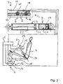
- a steering column 1 for a vehicle (not shown), which is only indicated, has a conventional one telescopic structure, due to its popularity in numerous versions is not further discussed here, since the present invention applies to all known Designs also retractable overall, not telescopically collapsible Steering columns can be used and the present invention is not the actual design relates to such steering columns.
- the steering column 1 has a steering wheel end area 2 and is provided with adjusting devices 3 provided, which can be triggered in the event of an accident to at least the To move the steering wheel end region 2 of the steering column 1 away from an occupant (not shown), who sits on a seat 4.
- the adjusting devices 3 are illustrated in the figure for the three Operating modes designed.
- a controller 5 detects occupant parameters by means of detection devices 6 and triggers an operating mode depending on the occupant parameters Adjustment devices 3 from.
- the adjustment devices 3 contain load suspension devices 7 with a first and a second load receiver or limiter 8 (A) or 9 (B), each with its own bolt 10 and 11 and a common load-bearing plate 12 contain the deformation devices (D) form.
- the load bearing plate 12 is with a telescopic part (not shown) the steering column 1 is firmly connected, and the carriage 13 is with the other telescopic part (not shown) of the steering column 1 firmly connected.
- the bolts 10 and 11 each have an explosive charge S, which the controller 5, which, for example, is connected to or integrated in an overall control system (not shown) for an airbag, each of which can be ignited independently of one another, to render each of the bolts 10 and 11 ineffective accordingly.
- the controller 5 To the controller 5 are as detection devices 6 state detection devices 13 of a belt buckle 14 connected in the form of a belt or buckle switch 15. This belt usage switch 15 results in a belt usage signal when the occupant is wearing his seat belt (not shown). If the belt usage signal is not generated, it is Control informs that the occupant is not properly buckled up.
- position detection devices 16 are contained in the detection devices 6, which are formed by a position switch 17 in a seat rail 18 of the seat 4.
- This position switch 17 leads to a near position signal when the seat 4 is in the position the position switch 17 has reached or closer than the position switch 17 on the steering column 1 is.
- the controller 5 receives the information that the occupant is one small person acts. If the near position signal is not generated, the control is above it informs that the occupant is a tall person.
- controller 5 set each of the three operating modes of the adjusting devices 3 according to FIG. 1.
- the controller 5 If the controller 5 has received the near position signal, it initiates the operating mode for a buckled or unbuckled "little woman".
- the controller fires in this mode 5 the explosive charges S of the two bolts 10 and 11, so that they become ineffective and the load receiving plate 12 and the slide 13 are decoupled.
- the controller also fires 5 shows a pyrotechnic explosive device 19 of a gas generator 20, and the one generated by it Gas acts on a piston 21 with a piston rod 22 connected to the end of the steering wheel 2 containing telescopic part (not shown) of the steering column 1 firmly connected is that the two telescopic parts (not shown) of the steering column 5 are pulled together.
- the parts 19 to 22 are components of the adjusting devices 3 and form together Drive devices 23.
- the controller 5 If the controller 5 has not received the near position signal, it checks whether the belt usage signal given is. If the belt usage signal is present, the controller 5 initiates the Operating mode for a buckled "big man". The controller fires in this mode 5 the explosive charge S only of the bolt 11, so that only this is ineffective and that Load receiving plate 12 and the carriage 13 are still coupled by the bolt 10. The Load receiver 8 (A) is thus effective to dissipate energy that occurs when the seat belt strikes "Big man" occurs on the steering wheel (not labeled). The drive devices 23 are not triggered.
- the controller 5 If the controller 5 receives neither the near position signal nor the belt usage signal, the controller 5 thus initiates the operating mode for an unbuckled "tall man". In this mode, the controller 5 does not ignite an explosive charge S, so that the load-receiving plate 12 and the carriage 13 are coupled by both bolts 10 and 11.
- the load receiver 8 (A) and the load receiver 9 (B) are thus effective to dissipate energy that Impact of the unbuckled "big man” on the steering wheel (not labeled) occurs.
- the drive devices 23 are not triggered.
- Signal lines between the controller 5 and the explosive charges S, the pyrotechnic The explosive device 19 and the detection devices 6 are shown as lines or lines in FIG. 2 located.
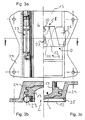
- 3a, 3b and 3c show a carriage 13 for receiving the steering (not shown) in its carriage receptacle 24 in Fig. 3a left from below and right from above and in the 3b and 3c each cut.
- the pyrotechnic gas generator 20 of the drive devices 23 is attached to the carriage receptacle 24 on the one hand and to the carriage 13 on the other hand.
- the load receiver 8 (A) and the load receiver 9 (B) are on the right side of FIG. 3a. shown in one piece in installation position.
- the load sensors 8 and 9 are on the one hand with the bolts 10 or 11 on the slide 13 and on the other hand on the slide receptacle 24 with screw connections 25 provided.
- the sliding telescopic part (not shown) of the steering column 1 is in the Recess L fixed.
- the drive devices 23 are shown separately in FIG. 4, as they are already in connection were explained with FIG. 2.
- Figure 5 shows above, i.e. in a ready-to-install condition, and below after actuation both load receptors 8 and 9, the load receiving plate 12, which is a stamped part is.
- the load limiter 8 (A) is designed such that it is by means of of the bolt 10 immediately tears at tear lines 26 when the load is exceeded. there the end of the load limiter 8 (A) inevitably slides over the load limiter 9 (B), whose bolt 11 initially moves in a slot 27 of the load limiter 9 (B).
- This Design advantageously leads to the pull-out forces of the two load sensors Add 8 (A) and 9 (B). If they ripped apart in parallel, only one would of the two load receptors A or B.
- the invention thus in particular makes a safety steering column created with a crash sled that has two load sensors for buckled and not buckled tall and small people.
- a control with a lock usage switch is a control with a lock usage switch.
- the crash slide for small people is used as a "distance slide" used and its load sensors are taken out of operation.
- Smaller people can preferably use an electrical seat position detection.
- the load sensors are of this type are built in a row, e.g. by means of a slot in a connection to the delayed Start that the load receptacles add up with the load.
- this embodiment relates to a safety steering column with pyrotechnic driven shortening for small drivers and peak load reduction for large drivers.
- this embodiment relates to a safety steering column with pyrotechnic driven shortening for small drivers and peak load reduction for large drivers.
- Steering columns are already partially supplemented to an airbag with a peak load reduction equipped for heavy persons.
- Practice has also shown that small and too dense Drivers positioned on the airbag may die to some extent as a result.
- the second embodiment also creates a solution for reducing peak loads for large drivers and in same system a shortening of the steering column for small drivers in the event of an accident.
- 6 to 8 show a steering column outer tube 28 and a steering column inner tube 29, which Represent telescopic parts of a steering column 1, the steering column inner tube 29 the steering wheel end region 2 of the steering column 1 contains.
- On the steering column outer tube 28 is an outer tube ring piston 30 attached, for example, by a clinch connection 31.
- the outer tube ring piston 30 contains a pyrotechnic cartridge 32 which is connected to control cables K with the control 5 (see Fig. 2) is connected.
- With the steering column inner tube 29 is an inner tube ring piston 33 firmly connected by a clinching connection 34 as well.
- This inner tube ring piston 33 contains one or more in slots in the second embodiment 35 mounted, correspondingly shaped cutting knife 36 as parts of deformation devices 6.
- the cutting knives 36 are mounted on a "tipping point" 37 such that they are at Drive via the inner tube ring piston 33 into the wall 38 of the steering column outer tube Cut 28 of the steering column 1.
- the cutting depth 39 of the chip 40 is by a correspondingly shaped stop 41 determined.
- the size of the chip 40 is proportional to that desired load bearing.
- the deformation devices 6 form load receivers 42.
- the outer tubular ring piston 30 and the inner tubular ring piston 33 form drive devices 23, which, like the load receivers 42, are components of the adjusting devices 3 of the Steering column 1 are.
- Fig. 7 shows the function with small drivers.
- the charge 43 presses the pyrotechnic Cartridge 32 connects the inner tube ring piston 33 to the steering column inner tube 29 down and away from an occupant (not shown).
- the pyrotechnic Cartridge 32 connects the inner tube ring piston 33 to the steering column inner tube 29 down and away from an occupant (not shown).
- one pressurized control pin 44 tilting the cutter 36 into position "Load bearing", i.e. for chip removal in the wall 38 of the steering column outer tube 28 the steering column 1.
- FIGS. 6 to 8 explain the invention as follows:
- Steering column tubes that can be pushed into one another are provided with “ring pistons", which are suitable for small drivers shorten the steering column by means of a pyrotechnic pressure build-up and to bring an inflating airbag a greater distance.
- ring pistons In one of the ring pistons a load-bearing mechanism is built in, which is used by tall drivers instead of shortening the steering column is effective and for small drivers using pyrotechnic pressure Function is set.
- the second ring piston is equipped with a load suspension mechanism. In the example shown, these are appropriately shaped and stored tiltable Knife. It can also be corrugated pipes, material-deforming balls or similar. act (in the figures not shown).
- the function of the load-bearing ring piston is fundamentally such that it automatically picks up and breaks down load when the inner steering column tube is relative is moved to the outside.
- the knife is machined into the outside Steering column tube pressed.
- this load pick-up can be used with a pyrotechnic ignition with the appropriate performance "overplayed", or the "knife” as in the example tilted out of function by a pressurized control pin.
- the inner and outer steering column tube designed for the largest possible difference in diameter.
- the outer steering column tube is positioned in bearings (not shown in the figures).
- the inner Steering column tube is form-fitting to the outside with corresponding ring pistons (grooves / shape) connected.
- the pair of ring pistons is e.g. by linking with one outer and one each inner tube connected.
- An annular piston contains a pyrotechnic charge, the pressure of which press the ring pistons away from each other and thus shorten the steering column or the steering wheel can pull away from the occupant in the direction of travel.
- Small drivers can also be found in the second embodiment e.g. through appropriate electronic monitoring systems or seat position detection using switches in the seat rail.
Landscapes
- Engineering & Computer Science (AREA)
- General Engineering & Computer Science (AREA)
- Mechanical Engineering (AREA)
- Chemical & Material Sciences (AREA)
- Combustion & Propulsion (AREA)
- Transportation (AREA)
- Steering Controls (AREA)
- Air Bags (AREA)
Claims (31)
- Colonne de direction pour un véhicule, comportant des dispositifs de déplacement (3) qui sont susceptibles d'être déclenchés en cas d'accident pour déplacer au moins une zone d'extrémité (2) côté volant de la colonne de direction (1) en éloignement d'un occupant; les dispositifs de déplacement (3) comprenant des dispositifs d'encaissement de charge (7) pour amortir un mouvement au moins de la zone d'extrémité (2) côté volant de la colonne de direction (1) en éloignement d'un occupant et étant conçus pour au moins deux modes de fonctionnement, une commande (5) étant prévue pour détecter des paramètres relatifs à l'occupant au moyen de dispositifs de détection (6) et pour déclencher un mode de fonctionnement des dispositifs de déplacement (3) en fonction des paramètres relatifs à l'occupant,
caractérisée en ce que
les dispositifs d'encaissement de charge (7) comprennent des dispositifs de déformation (6) qui sont activés ou désactivés au moyen de la commande (5) en fonction des paramètres relatifs à l'occupant pour réaliser un mode de fonctionnement déterminé des dispositifs de déplacement (3), et
en ce que les dispositifs de déformation (6) comprennent des goujons (10, 11) qui déforment le matériau le long d'une course de déplacement. - Colonne de direction selon la revendication 1, caractérisée en ce que les dispositifs de déplacement (3) comprennent des dispositifs d'entraínement (23) pour provoquer le déplacement au moins de la zone d'extrémité (2) côté volant de la colonne de direction (1) en éloignement d'un occupant, et
en ce qu'en cas d'accident les dispositifs d'entraínement (23) sont susceptibles d'être déclenchés par la commande (5) en fonction des paramètres relatifs à l'occupant. - Colonne de direction selon la revendication 2, caractérisée en ce que les dispositifs d'entraínement comprennent un générateur de gaz pyrotechnique (20 ; 32) et/ou sont susceptibles d'être déclenchés par voie électrique.
- Colonne de direction selon l'une des revendications 1 à 3, caractérisée en ce que les dispositifs de déplacement (3) comprennent des dispositifs d'encaissement de charge (7) pour amortir un mouvement au moins de la zone d'extrémité (2) côté volant de la colonne de direction (1) en éloignement d'un occupant, et en ce qu'en cas d'accident les dispositifs d'encaissement de charge (7) peuvent être amenés à fonctionner directement ou indirectement par la commande (5) en fonction des paramètres relatifs à l'occupant.
- Colonne de direction selon la revendication 4, caractérisée en ce que les dispositifs d'encaissement de charge (7) comprennent au moins deux étages (A, B) qui, en cas d'accident, peuvent être amenés à fonctionner directement ou indirectement par la commande (5) en fonction des paramètres relatifs à l'occupant.
- Colonne de direction selon la revendication 5, caractérisée en ce que les étages (A, B) des dispositifs d'encaissement de charge (7) sont susceptibles d'être amenés à fonctionner individuellement ou simultanément avec addition de leurs propriétés d'encaissement de charge.
- Colonne de direction selon la revendication 6, caractérisée en ce que les étages (A, B) des dispositifs d'encaissement de charge (7) présentent chacun des propriétés d'encaissement de charge différentes.
- Colonne de direction selon l'une des revendications 4 à 7, caractérisée en ce qu'en cas d'accident, les dispositifs d'encaissement de charge (7) ou le cas échéant chaque étage (A, B) individuellement peuvent être coupés directement ou indirectement par la commande (5) en fonction des paramètres relatifs à l'occupant.
- Colonne de direction selon l'une des revendications 4 à 8, caractérisée en ce que les dispositifs d'encaissement de charge (7) ou le cas échéant un étage (A, B) de ceux-ci comprennent des dispositifs de déformation (6) avec des lames de coupe (36) enlevant des copeaux le long d'une course de déplacement et/ou comprennent des dispositifs de freinage.
- Colonne de direction selon la revendication 9, caractérisée en ce que les dispositifs de freinage comprennent un chariot de freinage.
- Colonne de direction selon la revendication 10, caractérisée en ce que le chariot de freinage présente au moins deux étages de force de freinage.
- Colonne de direction selon l'une des revendications précédentes, caractérisée en ce que la commande (5) est conçue pour détecter au moyen des dispositifs de détection (6) la position assise, l'état d'application de ceinture, la taille, le poids et/ou la posture corporelle de l'occupant.
- Colonne de direction selon la revendication 12 en combinaison avec l'une ou l'autre des revendications 2 et 3, caractérisée en ce que la commande (5) est conçue pour déclencher les dispositifs d'entraínement (23) en fonction de la position assise de l'occupant.
- Colonne de direction selon la revendication 13, caractérisée en ce que la commande (5) est conçue pour détecter au moyen des dispositifs de détection une distance prédéterminée ou un passage au-dessous d'une distance prédéterminée de la position du siège (4) pour l'occupant par rapport au volant.
- Colonne de direction selon la revendication 14, caractérisée en ce que la commande (5) est conçue pour déclencher un mode de fonctionnement des dispositifs de déplacement (3), dans lequel, en cas d'accident, les dispositifs d'entraínement (23) des dispositifs de déplacement (3) sont déclenchés lors de la détection d'une distance prédéterminée ou de la détection d'un passage au-dessous d'une distance prédéterminée de la position du siège (4) pour l'occupant par rapport au volant.
- Colonne de direction selon l'une ou l'autre des revendications 14 et 15 en combinaison avec l'une des revendications 4 à 11, caractérisée en ce que la commande (5) est conçue pour faire fonctionner les dispositifs d'encaissement de charge (7) ou le cas échéant chaque étage (A, B) individuellement en fonction de l'état d'application de ceinture et/ou de la position assise de l'occupant.
- Colonne de direction selon la revendication 16, caractérisée en ce que la commande (5) est conçue pour déclencher un mode de fonctionnement des dispositifs de déplacement (3) dans lequel, en cas d'accident et en présence d'un occupant non attaché, les dispositifs d'encaissement de charge (7) ou au moins un étage (A, B) de ceux-ci est ou sont actif(s).
- Colonne de direction selon l'une ou l'autre des revendications 16 et 17, caractérisée en ce que la commande (5) est conçue pour déclencher un mode de fonctionnement des dispositifs de déplacement (3), dans lequel, en cas d'accident, lors de la détection d'une distance déterminée ou de la détection d'un passage au-dessous d'une distance prédéterminée de la position du siège (4) pour l'occupant par rapport au volant, les dispositifs d'encaissement de charge (7) ou au moins un étage (A, B) de ceux-ci est ou sont inactif(s).
- Colonne de direction selon l'une des revendications précédentes, caractérisée en ce que les dispositifs de détection (6) comprennent des dispositifs de reconnaissance de position (16) du siège (4) pour l'occupant, des dispositifs de reconnaissance d'état (13) du verrou de ceinture (14) pour la ceinture de sécurité de l'occupant, des dispositifs de reconnaissance de taille, de poids et/ou de posture corporelle par rapport à l'occupant.
- Colonne de direction selon la revendication 19, caractérisée en ce que les dispositifs de reconnaissance de position (16) du siège (4) pour l'occupant comprennent au moins un commutateur électrique ou optique (17) dans ou en relation avec des rails de guidage de siège (18), et/ou en ce que les dispositifs de reconnaissance d'état (13) du verrou de ceinture (14) pour la ceinture de sécurité de l'occupant comprennent au moins un commutateur électrique ou optique (15) relatif à l'utilisation du verrou.
- Procédé de déplacement pour une colonne de direction (1) d'un véhicule automobile, dans lequel, en cas d'accident, au moins une zone d'extrémité (2) côté volant de la colonne de direction (1) est déplacée en éloignement d'un occupant au moyen de dispositifs de déplacement (3), des paramètres relatifs à l'occupant sont détectés au moyen de dispositifs de détection (6), et le déplacement au moins de la zone d'extrémité (2) côté volant de la colonne de direction (1) en éloignement de l'occupant s'effectue au moyen d'une commande (5) en fonction des paramètres relatifs à l'occupant suivant un mode de fonctionnement parmi plusieurs modes de fonctionnement des dispositifs de déplacement (3),
caractérisé en ce que
pour réaliser un certain mode de fonctionnement des dispositifs de déplacement (3), des dispositifs de déformation (6), destinés à l'encaissement de charge avec amortissement des mouvements, sont activés ou désactivés au moyen de la commande (5) en fonction des paramètres relatifs à l'occupant, et
en ce que, lorsque les dispositifs de déformation sont actifs, en cas d'accident, au moins un goujon (10, 11) des dispositifs de déformation (6) est déplacé en déformant le matériau le long d'une course de déplacement pour l'encaissement de charge amortissant les mouvements. - Procédé de déplacement pour une colonne de direction selon la revendication 21, caractérisé en ce qu'un entraínement des dispositifs de déplacement (3) est déclenché en cas d'accident en fonction des paramètres relatifs à l'occupant pour provoquer le déplacement au moins de la zone d'extrémité (2) côté volant de la colonne de direction (1) en éloignement de l'occupant.
- Procédé de déplacement pour une colonne de direction selon l'une ou l'autre des revendications 21 et 22, caractérisé en ce qu'un déplacement au moins de la zone d'extrémité (2) côté volant de la colonne de direction (1) en éloignement d'un occupant en cas d'accident est amorti en fonction des paramètres relatifs à l'occupant.
- Procédé de déplacement pour une colonne de direction selon la revendication 23, caractérisé en ce qu'un amortissement du déplacement au moins de la zone d'extrémité (2) côté volant de la colonne de direction (1) en éloignement d'un occupant en cas d'accident est coupé en fonction des paramètres relatifs à l'occupant.
- Procédé de déplacement pour une colonne de direction selon la revendication 23, caractérisé en ce que la coupure de l'amortissement du déplacement au moins de la zone d'extrémité (2) côté volant de la colonne de direction (1) en éloignement d'un occupant en cas d'accident est réalisée en fonction des paramètres relatifs à l'occupant, et ceci au choix dans des étages individuels (A, B).
- Procédé de déplacement pour une colonne de direction selon l'une des revendications 21 à 25, caractérisé en ce que la position assise, l'état d'application de ceinture, la taille, le poids et/ou la posture corporelle de l'occupant est ou sont détecté(s) comme paramètres relatifs à l'occupant.
- Procédé de déplacement pour une colonne de direction selon la revendication 26, caractérisé en ce que les dispositifs de déplacement (3) sont amenés à fonctionner en fonction de la position assise de l'occupant.
- Procédé de déplacement pour une colonne de direction selon la revendication 27, caractérisé en ce qu'en cas d'accident, lors de la détection d'une distance prédéterminée ou de la détection d'un passage au-dessous d'une distance prédéterminée de la position du siège (4) pour l'occupant par rapport au volant, les dispositifs de déplacement (3) ne sont pas amenés à fonctionner suivant un mode de fonctionnement.
- Procédé de déplacement pour une colonne de direction selon l'une des revendications 26 à 28, caractérisé en ce que les dispositifs de déplacement (3) sont amortis en fonction de l'état d'application de ceinture et/ou de la position assise de l'occupant.
- Procédé de déplacement pour une colonne de direction selon la revendication 29, caractérisé en ce qu'en cas d'accident et en présence d'un occupant non attaché, les dispositifs de déplacement (3) sont amortis complètement ou partiellement suivant un mode de fonctionnement.
- Procédé de déplacement pour une colonne de direction selon l'une ou l'autre des revendications 29 et 30, caractérisé en ce qu'en cas d'accident, lors de la détection d'une distance prédéterminée ou de la détection d'un passage au-dessous d'une distance prédéterminée de la position du siège (4) pour l'occupant par rapport au volant, les dispositifs de déplacement (3) sont amortis complètement ou partiellement suivant un mode de fonctionnement.
Priority Applications (2)
| Application Number | Priority Date | Filing Date | Title |
|---|---|---|---|
| EP03017865A EP1384643B1 (fr) | 1999-06-09 | 2000-06-09 | Colonne de direction et procédé de réglage d'une colonne de direction |
| EP04021210.2A EP1510435B1 (fr) | 1999-06-09 | 2000-06-09 | Colonne de direction et procédé de réglage d'une colonne de direction |
Applications Claiming Priority (5)
| Application Number | Priority Date | Filing Date | Title |
|---|---|---|---|
| DE29910056U | 1999-06-09 | ||
| DE29910056 | 1999-06-09 | ||
| DE29910058U | 1999-06-09 | ||
| DE29910058 | 1999-06-09 | ||
| PCT/DE2000/001889 WO2000076832A1 (fr) | 1999-06-09 | 2000-06-09 | Colonne de direction et procede de reglage d'une colonne de direction |
Related Child Applications (2)
| Application Number | Title | Priority Date | Filing Date |
|---|---|---|---|
| EP04021210.2A Division EP1510435B1 (fr) | 1999-06-09 | 2000-06-09 | Colonne de direction et procédé de réglage d'une colonne de direction |
| EP03017865.1 Division-Into | 2003-08-05 |
Publications (2)
| Publication Number | Publication Date |
|---|---|
| EP1187752A1 EP1187752A1 (fr) | 2002-03-20 |
| EP1187752B1 true EP1187752B1 (fr) | 2004-09-08 |
Family
ID=26062564
Family Applications (3)
| Application Number | Title | Priority Date | Filing Date |
|---|---|---|---|
| EP03017865A Expired - Lifetime EP1384643B1 (fr) | 1999-06-09 | 2000-06-09 | Colonne de direction et procédé de réglage d'une colonne de direction |
| EP04021210.2A Expired - Lifetime EP1510435B1 (fr) | 1999-06-09 | 2000-06-09 | Colonne de direction et procédé de réglage d'une colonne de direction |
| EP00945629A Expired - Lifetime EP1187752B1 (fr) | 1999-06-09 | 2000-06-09 | Colonne de direction et procede de reglage d'une colonne de direction |
Family Applications Before (2)
| Application Number | Title | Priority Date | Filing Date |
|---|---|---|---|
| EP03017865A Expired - Lifetime EP1384643B1 (fr) | 1999-06-09 | 2000-06-09 | Colonne de direction et procédé de réglage d'une colonne de direction |
| EP04021210.2A Expired - Lifetime EP1510435B1 (fr) | 1999-06-09 | 2000-06-09 | Colonne de direction et procédé de réglage d'une colonne de direction |
Country Status (5)
| Country | Link |
|---|---|
| EP (3) | EP1384643B1 (fr) |
| AU (1) | AU5964500A (fr) |
| DE (2) | DE50007693D1 (fr) |
| ES (3) | ES2226874T3 (fr) |
| WO (1) | WO2000076832A1 (fr) |
Cited By (2)
| Publication number | Priority date | Publication date | Assignee | Title |
|---|---|---|---|---|
| DE102009009577B3 (de) * | 2009-02-19 | 2010-05-27 | Thyssenkrupp Presta Ag | Lenksäule für eine Kraftfahrzeug |
| DE102012111890B3 (de) * | 2012-12-06 | 2013-12-24 | Thyssenkrupp Presta Aktiengesellschaft | Lenksäule für ein Kraftfahrzeug |
Families Citing this family (3)
| Publication number | Priority date | Publication date | Assignee | Title |
|---|---|---|---|---|
| US6581966B2 (en) * | 2001-01-05 | 2003-06-24 | Ford Global Technologies, Inc. | Twin axis steering wheel system |
| US7048305B2 (en) * | 2002-05-07 | 2006-05-23 | Thyssenkrupp Presta Ag | Safety steering and mechanism and a method of operating |
| DE102012100626B3 (de) | 2012-01-25 | 2013-02-21 | Thyssenkrupp Presta Aktiengesellschaft | Lenksäule für ein Kraftfahrzeug |
Family Cites Families (6)
| Publication number | Priority date | Publication date | Assignee | Title |
|---|---|---|---|---|
| NL7502142A (en) * | 1975-02-21 | 1976-08-24 | Noord Nederlandsche Maschf | Impact-absorbing device for rail vehicle - has telescopic elements of which one cuts into the other on impact |
| JP2776102B2 (ja) * | 1991-12-11 | 1998-07-16 | 日産自動車株式会社 | 車両用安全装置 |
| SE507771C2 (sv) * | 1996-11-21 | 1998-07-13 | Volvo Ab | Anordning och förfarande för skydd av åkande i fordon |
| SE510856C2 (sv) * | 1997-06-23 | 1999-06-28 | Volvo Ab | Kraftupptagande anordning för skydd av åkande i fordon |
| DE19829239A1 (de) * | 1997-06-30 | 1999-01-07 | Volkswagen Ag | Lenkvorrichtung für ein Fahrzeug |
| CN1303340A (zh) * | 1998-05-11 | 2001-07-11 | 伊诺瓦技术开发有限责任公司 | 汽车安全转向柱、安全系统和带安全系统的汽车及安全方法 |
-
2000
- 2000-06-09 EP EP03017865A patent/EP1384643B1/fr not_active Expired - Lifetime
- 2000-06-09 EP EP04021210.2A patent/EP1510435B1/fr not_active Expired - Lifetime
- 2000-06-09 DE DE50007693T patent/DE50007693D1/de not_active Expired - Lifetime
- 2000-06-09 ES ES00945629T patent/ES2226874T3/es not_active Expired - Lifetime
- 2000-06-09 DE DE50011087T patent/DE50011087D1/de not_active Expired - Lifetime
- 2000-06-09 WO PCT/DE2000/001889 patent/WO2000076832A1/fr not_active Ceased
- 2000-06-09 ES ES04021210.2T patent/ES2440465T3/es not_active Expired - Lifetime
- 2000-06-09 AU AU59645/00A patent/AU5964500A/en not_active Abandoned
- 2000-06-09 EP EP00945629A patent/EP1187752B1/fr not_active Expired - Lifetime
- 2000-06-09 ES ES03017865T patent/ES2248691T3/es not_active Expired - Lifetime
Cited By (5)
| Publication number | Priority date | Publication date | Assignee | Title |
|---|---|---|---|---|
| DE102009009577B3 (de) * | 2009-02-19 | 2010-05-27 | Thyssenkrupp Presta Ag | Lenksäule für eine Kraftfahrzeug |
| WO2010094050A1 (fr) | 2009-02-19 | 2010-08-26 | Thyssenkrupp Presta Aktiengesellschaft | Colonne de direction pour un véhicule |
| DE102012111890B3 (de) * | 2012-12-06 | 2013-12-24 | Thyssenkrupp Presta Aktiengesellschaft | Lenksäule für ein Kraftfahrzeug |
| WO2014086439A1 (fr) | 2012-12-06 | 2014-06-12 | Thyssenkrupp Presta Aktiengesellschaft | Colonne de direction pour véhicule à moteur |
| US9540032B2 (en) | 2012-12-06 | 2017-01-10 | Thyssenkrupp Presta Aktiengesellschaft | Steering column for a motor vehicle |
Also Published As
| Publication number | Publication date |
|---|---|
| ES2226874T3 (es) | 2005-04-01 |
| WO2000076832A1 (fr) | 2000-12-21 |
| EP1384643A2 (fr) | 2004-01-28 |
| EP1510435A3 (fr) | 2009-09-30 |
| EP1510435A2 (fr) | 2005-03-02 |
| DE50007693D1 (de) | 2004-10-14 |
| EP1384643A3 (fr) | 2004-02-04 |
| EP1384643B1 (fr) | 2005-08-31 |
| EP1187752A1 (fr) | 2002-03-20 |
| EP1510435B1 (fr) | 2013-09-25 |
| ES2248691T3 (es) | 2006-03-16 |
| ES2440465T3 (es) | 2014-01-29 |
| DE50011087D1 (de) | 2005-10-06 |
| WO2000076832A8 (fr) | 2001-04-19 |
| AU5964500A (en) | 2001-01-02 |
Similar Documents
| Publication | Publication Date | Title |
|---|---|---|
| DE19938938B4 (de) | Fahrzeuginsassen-Schutzsystem | |
| DE19847385C1 (de) | Stoßfängeranordnung | |
| EP0691910B1 (fr) | Dispositif de securite pour vehicules automobiles | |
| DE19931804A1 (de) | Fahrzeuginsassenschutzvorrichtung | |
| EP1016567A2 (fr) | Dispositif de sécurité pour véhicule protégeant les pieds des occupants | |
| DE2338026C3 (de) | Aufprallschutzvorrichtung für den Fahrer eines Kraftfahrzeuges | |
| DE102010062550A1 (de) | Insassensicherheitssystem | |
| EP1178916A1 (fr) | Ensemble capot avant | |
| DE2409159A1 (de) | Sicherheitsgurtsystem fuer ein kraftfahrzeug | |
| EP2096007A1 (fr) | Dispositif de protection de piétons au capot avant d'un véhicule automobile | |
| WO2019180213A1 (fr) | Ensemble formant siège de véhicule | |
| EP1077863B1 (fr) | Colonne de direction de securite, systeme de securite pour un vehicule, vehicule equipe d'un systeme de securite et procede de securite | |
| DE4414432A1 (de) | Kraftfahrzeug | |
| DE60025984T2 (de) | Einrichtung zum Schutz der Insassen | |
| DE10261870A1 (de) | Kraftfahrzeug mit Vorrichtungen zum Anheben eines Deckels oder Deckelteils bei einer Fußgängerkollision sowie zur Rückführung desselben | |
| DE602004008322T2 (de) | Sicherheitsanordnung | |
| EP1187752B1 (fr) | Colonne de direction et procede de reglage d'une colonne de direction | |
| DE69700078T2 (de) | Aktive Kontrolle des Insassenkörpers mit einem Rückhaltesystem mit begrenzter Zugkraft während eines Frontalaufpralls | |
| DE102005021725B4 (de) | Fahrzeug | |
| EP1369297B1 (fr) | Véhicule automobile et procédé pour reduire le choc sur un voyageur en cas de collision | |
| DE10020660A1 (de) | Fahrzeug, insbesondere Kraftfahrzeug | |
| EP1202897B1 (fr) | Colonne de direction et procede de deplacement d'une colonne de direction | |
| DE19820214B4 (de) | Kraftfahrzeug mit einem Fahrersitz | |
| DE102022003927B4 (de) | Verfahren zum Betrieb einer Insassenrückhaltevorrichtung eines Fahrzeuges | |
| DE10061043A1 (de) | Sicherheitsvorrichtung an Fahrzeugsitzen |
Legal Events
| Date | Code | Title | Description |
|---|---|---|---|
| PUAI | Public reference made under article 153(3) epc to a published international application that has entered the european phase |
Free format text: ORIGINAL CODE: 0009012 |
|
| 17P | Request for examination filed |
Effective date: 20020109 |
|
| AK | Designated contracting states |
Kind code of ref document: A1 Designated state(s): AT BE CH CY DE DK ES FI FR GB GR IE IT LI LU MC NL PT SE |
|
| AX | Request for extension of the european patent |
Free format text: AL;LT;LV;MK;RO;SI |
|
| 17Q | First examination report despatched |
Effective date: 20020701 |
|
| RAP1 | Party data changed (applicant data changed or rights of an application transferred) |
Owner name: THYSSENKRUPP PRESTA AG |
|
| GRAP | Despatch of communication of intention to grant a patent |
Free format text: ORIGINAL CODE: EPIDOSNIGR1 |
|
| GRAS | Grant fee paid |
Free format text: ORIGINAL CODE: EPIDOSNIGR3 |
|
| GRAA | (expected) grant |
Free format text: ORIGINAL CODE: 0009210 |
|
| AK | Designated contracting states |
Kind code of ref document: B1 Designated state(s): DE ES FR GB IT |
|
| REG | Reference to a national code |
Ref country code: GB Ref legal event code: FG4D Free format text: NOT ENGLISH |
|
| GBT | Gb: translation of ep patent filed (gb section 77(6)(a)/1977) |
Effective date: 20040908 |
|
| REG | Reference to a national code |
Ref country code: IE Ref legal event code: FG4D Free format text: GERMAN |
|
| REF | Corresponds to: |
Ref document number: 50007693 Country of ref document: DE Date of ref document: 20041014 Kind code of ref document: P |
|
| LTIE | Lt: invalidation of european patent or patent extension |
Effective date: 20040908 |
|
| REG | Reference to a national code |
Ref country code: ES Ref legal event code: FG2A Ref document number: 2226874 Country of ref document: ES Kind code of ref document: T3 |
|
| REG | Reference to a national code |
Ref country code: IE Ref legal event code: FD4D |
|
| ET | Fr: translation filed | ||
| PLBE | No opposition filed within time limit |
Free format text: ORIGINAL CODE: 0009261 |
|
| STAA | Information on the status of an ep patent application or granted ep patent |
Free format text: STATUS: NO OPPOSITION FILED WITHIN TIME LIMIT |
|
| 26N | No opposition filed |
Effective date: 20050609 |
|
| REG | Reference to a national code |
Ref country code: FR Ref legal event code: PLFP Year of fee payment: 16 |
|
| PG25 | Lapsed in a contracting state [announced via postgrant information from national office to epo] |
Ref country code: IT Free format text: LAPSE BECAUSE OF NON-PAYMENT OF DUE FEES Effective date: 20150609 |
|
| PGRI | Patent reinstated in contracting state [announced from national office to epo] |
Ref country code: IT Effective date: 20160711 |
|
| REG | Reference to a national code |
Ref country code: FR Ref legal event code: PLFP Year of fee payment: 17 |
|
| REG | Reference to a national code |
Ref country code: FR Ref legal event code: PLFP Year of fee payment: 18 |
|
| REG | Reference to a national code |
Ref country code: FR Ref legal event code: PLFP Year of fee payment: 19 |
|
| PGFP | Annual fee paid to national office [announced via postgrant information from national office to epo] |
Ref country code: DE Payment date: 20180830 Year of fee payment: 19 |
|
| PGFP | Annual fee paid to national office [announced via postgrant information from national office to epo] |
Ref country code: IT Payment date: 20181218 Year of fee payment: 19 Ref country code: ES Payment date: 20181218 Year of fee payment: 19 Ref country code: GB Payment date: 20181219 Year of fee payment: 19 |
|
| PGFP | Annual fee paid to national office [announced via postgrant information from national office to epo] |
Ref country code: FR Payment date: 20190619 Year of fee payment: 20 |
|
| REG | Reference to a national code |
Ref country code: DE Ref legal event code: R119 Ref document number: 50007693 Country of ref document: DE |
|
| GBPC | Gb: european patent ceased through non-payment of renewal fee |
Effective date: 20190609 |
|
| PG25 | Lapsed in a contracting state [announced via postgrant information from national office to epo] |
Ref country code: DE Free format text: LAPSE BECAUSE OF NON-PAYMENT OF DUE FEES Effective date: 20200101 Ref country code: GB Free format text: LAPSE BECAUSE OF NON-PAYMENT OF DUE FEES Effective date: 20190609 Ref country code: IT Free format text: LAPSE BECAUSE OF NON-PAYMENT OF DUE FEES Effective date: 20190609 |
|
| REG | Reference to a national code |
Ref country code: ES Ref legal event code: FD2A Effective date: 20201027 |
|
| PG25 | Lapsed in a contracting state [announced via postgrant information from national office to epo] |
Ref country code: ES Free format text: LAPSE BECAUSE OF NON-PAYMENT OF DUE FEES Effective date: 20190610 |