EP1188537A2 - Une tête chauffée pour alimenter une buse d'injection pour mouler des matières plastiques - Google Patents
Une tête chauffée pour alimenter une buse d'injection pour mouler des matières plastiques Download PDFInfo
- Publication number
- EP1188537A2 EP1188537A2 EP01121814A EP01121814A EP1188537A2 EP 1188537 A2 EP1188537 A2 EP 1188537A2 EP 01121814 A EP01121814 A EP 01121814A EP 01121814 A EP01121814 A EP 01121814A EP 1188537 A2 EP1188537 A2 EP 1188537A2
- Authority
- EP
- European Patent Office
- Prior art keywords
- heated head
- head according
- piston element
- heated
- needle
- Prior art date
- Legal status (The legal status is an assumption and is not a legal conclusion. Google has not performed a legal analysis and makes no representation as to the accuracy of the status listed.)
- Withdrawn
Links
Images


Classifications
-
- B—PERFORMING OPERATIONS; TRANSPORTING
- B29—WORKING OF PLASTICS; WORKING OF SUBSTANCES IN A PLASTIC STATE IN GENERAL
- B29C—SHAPING OR JOINING OF PLASTICS; SHAPING OF MATERIAL IN A PLASTIC STATE, NOT OTHERWISE PROVIDED FOR; AFTER-TREATMENT OF THE SHAPED PRODUCTS, e.g. REPAIRING
- B29C45/00—Injection moulding, i.e. forcing the required volume of moulding material through a nozzle into a closed mould; Apparatus therefor
- B29C45/17—Component parts, details or accessories; Auxiliary operations
- B29C45/26—Moulds
- B29C45/27—Sprue channels ; Runner channels or runner nozzles
- B29C45/28—Closure devices therefor
- B29C45/2806—Closure devices therefor consisting of needle valve systems
- B29C45/281—Drive means therefor
-
- B—PERFORMING OPERATIONS; TRANSPORTING
- B29—WORKING OF PLASTICS; WORKING OF SUBSTANCES IN A PLASTIC STATE IN GENERAL
- B29C—SHAPING OR JOINING OF PLASTICS; SHAPING OF MATERIAL IN A PLASTIC STATE, NOT OTHERWISE PROVIDED FOR; AFTER-TREATMENT OF THE SHAPED PRODUCTS, e.g. REPAIRING
- B29C45/00—Injection moulding, i.e. forcing the required volume of moulding material through a nozzle into a closed mould; Apparatus therefor
- B29C45/17—Component parts, details or accessories; Auxiliary operations
- B29C45/26—Moulds
- B29C45/27—Sprue channels ; Runner channels or runner nozzles
- B29C2045/2772—Means for fixing the nozzle to the manifold
Definitions
- the present invention relates to a heated head for feeding a nozzle for moulding plastics materials, of the type defined in the preamble to Claim 1.
- a heated injector head 10 is fitted in a mould 11 for moulding plastics materials.
- the nozzle 10 has an injector duct 12 for injecting the molten plastics material into a mould cavity 13 through an injector orifice 14.
- the injector orifice 14 is opened and closed by the lower end of a valve needle 15 controlled for vertical sliding movement by a pneumatic actuating device 16 mounted alongside a heated head 17 in which a feeder duct 18 is formed which is in communication with the injector duct 12 of the nozzle.
- the actuating device 16 includes a piston rod 19 which can slide horizontally and which is mechanically coupled to the upper end of the pin by means of an L-shaped lever 20.
- Resistors 21 are incorporated in the head 17 near the feeder duct 18 in order to keep the material to be injected warm and in a fluid state.
- One object of the present invention is to provide an improved heated feeder head which is able to overcome the aforesaid disadvantages of the prior art and having, in particular, a configuration which makes it possible to manufacture a compact nozzle assembly.
- a heated head according to the present invention is generally indicated 30 and incorporates a pneumatic device for operating a valve needle 35 of a heated injector nozzle 50.
- the heated head 30 is formed by joining two complementary bodies 31, 32 so as to define an internal chamber 33 with a piston element 34 slidably housed therein which is connected to the head 35a of the valve needle 35.
- the needle 35 is preferably positioned along the central longitudinal axis of the piston element 34.
- a cavity 36 is formed in the lower portion of the piston element 34 which on one side defines an undercut 37 for axially retaining the enlarged head 35a of the needle, thereby securing the needle to the piston when this latter reciprocates inside the chamber 33.
- the cavity 36 constitutes a free space enabling the piston to slide transverse the needle when it is necessary to disconnect these two elements.
- axial and transverse should be understood as in relation to the longitudinal axis x of the nozzle.
- the lower body 32 forms a seat 60 for a sealing sleeve 61 and a tubular axial formation 62, threaded on the outside for engaging a ring nut 63 shaped like an inverted cup and operable to lock into position the sealing sleeve 61.
- a duct 38 for feeding the molten plastics material is also formed inside the heated head 30, along with two seats 39, 40 (see Figure 3) for housing resistor elements of a known type (not shown), and two ducts 41, 42 in communication with the lower and upper portions respectively of the internal chamber 33, for providing air flows which cause the piston 34 and the rod 35 to rise and fall.
- Grooves 43 are formed in the outer cylindrical surface of the piston element 34 for housing seal rings 43a (shown in Figure 2, for the sake of simplicity, on the right-hand portion of the piston element 34) made of metal or, in any case able to resist high temperatures. It is advantageous to use piston rings of the type used on the pistons of internal combustion engines.
- a cavity 44 is formed with the upper portion of a heated nozzle 50 fitted therein, this nozzle preferably being of a conventional type with a core tube 52 defining an injection duct 51 in which the valve needle 35 slides co-axially and centrally.
- the manufacturing and operating characteristics of the heated nozzle 50 are not per se relevant to the embodiment of the invention, and will therefore not be discussed here.
- the heated head of the present invention makes it possible to make the assembly considerably smaller, since the needle actuating device is incorporated inside the head itself.
- the coaxial position of the needle 35 and of its operating rod makes it possible to act on the needle along its longitudinal axis x, thus eliminating any transverse stress.
- the heated head of the invention can advantageously be coupled to nozzles of different diameters and lengths, provided the injector duct and valve needle are arranged coaxially.
- Figure 2 shows an example with a nozzle 50 having a restricted diameter, with an annular adapter 45 for it housed in the cavity 44.
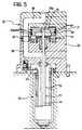
- Figure 5 shows another example, in which a larger-diameter nozzle is fitted without an annular adapter.
- a tubular seal element 53 is arranged, which in the preferred embodiment is partially housed in a cavity 54 formed in the lower body 32.
- a tubular seal element 55 similar to the seal element 54, is inserted through the feeder duct 38 at the interface between the bodies 31 and 32 of the head 30.
Landscapes
- Engineering & Computer Science (AREA)
- Manufacturing & Machinery (AREA)
- Mechanical Engineering (AREA)
- Injection Moulding Of Plastics Or The Like (AREA)
- Processing And Handling Of Plastics And Other Materials For Molding In General (AREA)
Applications Claiming Priority (2)
| Application Number | Priority Date | Filing Date | Title |
|---|---|---|---|
| ITTO000862 | 2000-09-13 | ||
| IT2000TO000862A IT1320639B1 (it) | 2000-09-13 | 2000-09-13 | Testa riscaldata di alimentazione di un ugello di iniezione per lostampaggio di materiali plastici. |
Publications (2)
| Publication Number | Publication Date |
|---|---|
| EP1188537A2 true EP1188537A2 (fr) | 2002-03-20 |
| EP1188537A3 EP1188537A3 (fr) | 2003-03-26 |
Family
ID=11458034
Family Applications (1)
| Application Number | Title | Priority Date | Filing Date |
|---|---|---|---|
| EP01121814A Withdrawn EP1188537A3 (fr) | 2000-09-13 | 2001-09-11 | Une tête chauffée pour alimenter une buse d'injection pour mouler des matières plastiques |
Country Status (2)
| Country | Link |
|---|---|
| EP (1) | EP1188537A3 (fr) |
| IT (1) | IT1320639B1 (fr) |
Cited By (13)
| Publication number | Priority date | Publication date | Assignee | Title |
|---|---|---|---|---|
| US6769901B2 (en) | 2000-04-12 | 2004-08-03 | Mold-Masters Limited | Injection nozzle system for an injection molding machine |
| US6921259B2 (en) | 2002-02-21 | 2005-07-26 | Mold-Masters Limited | Valve pin guide for a valve-gated nozzle |
| US6988883B2 (en) | 2001-10-03 | 2006-01-24 | Mold-Masters Limited | Injection molding apparatus having a nozzle tip and a tip surrounding piece of equal thermal conductivity |
| US7018197B2 (en) | 2001-10-05 | 2006-03-28 | Mold-Masters Limited | Gap seal between nozzle components |
| US7025585B2 (en) | 2002-04-12 | 2006-04-11 | Gellert Jobst U | Mold gate insert with a thermal barrier |
| US7025586B2 (en) | 2002-07-30 | 2006-04-11 | Mold-Masters Limited | Valve pin guidance and alignment system for an injection molding apparatus |
| US7108503B2 (en) | 2001-10-03 | 2006-09-19 | Mold-Master Limited | Injection molding nozzle |
| US7128566B2 (en) | 2002-02-21 | 2006-10-31 | Mold-Masters Limited | Valve pin guiding tip for a nozzle |
| US7137807B2 (en) | 2002-11-21 | 2006-11-21 | Mold-Masters Limited | Hot runner nozzle with a tip, a tip surrounding piece and an alignment piece |
| US7165965B2 (en) | 2002-12-09 | 2007-01-23 | Mold-Masters Limited | Nozzle tip and seal |
| US7189071B2 (en) | 2003-02-12 | 2007-03-13 | Mold-Masters Limited | Telescopic manifold nozzle seal |
| US7874833B2 (en) | 2009-05-03 | 2011-01-25 | Mold-Masters (2007) Limited | Injection molding runner apparatus having pressure seal |
| CN104085089A (zh) * | 2014-06-16 | 2014-10-08 | 苏州好特斯模具有限公司 | 一种阀针导流套 |
Family Cites Families (3)
| Publication number | Priority date | Publication date | Assignee | Title |
|---|---|---|---|---|
| US4832593A (en) * | 1988-01-25 | 1989-05-23 | Husky Injection Molding Systems Ltd. | Large nozzle for hot runner mold |
| FR2641227B1 (fr) * | 1988-12-30 | 1991-09-13 | Leonard Roland | Buse de moule a obturation commandee pour l'injection de matiere plastique |
| US5948448A (en) * | 1997-11-18 | 1999-09-07 | Eurotool, Inc. | Apparatus for controlling plastic melt flow in injection molding machines |
-
2000
- 2000-09-13 IT IT2000TO000862A patent/IT1320639B1/it active
-
2001
- 2001-09-11 EP EP01121814A patent/EP1188537A3/fr not_active Withdrawn
Cited By (17)
| Publication number | Priority date | Publication date | Assignee | Title |
|---|---|---|---|---|
| US7182591B2 (en) | 2000-04-12 | 2007-02-27 | Mold-Masters Limited | Injection nozzle system and injection molding machine incorporating same |
| US6769901B2 (en) | 2000-04-12 | 2004-08-03 | Mold-Masters Limited | Injection nozzle system for an injection molding machine |
| US7507081B2 (en) | 2000-04-12 | 2009-03-24 | Mold-Masters (2007) Limited | Injection nozzle system for an injection molding machine |
| US6988883B2 (en) | 2001-10-03 | 2006-01-24 | Mold-Masters Limited | Injection molding apparatus having a nozzle tip and a tip surrounding piece of equal thermal conductivity |
| US7891969B2 (en) | 2001-10-03 | 2011-02-22 | Mold-Masters (2007) Limited | Injection molding nozzle |
| US7108503B2 (en) | 2001-10-03 | 2006-09-19 | Mold-Master Limited | Injection molding nozzle |
| US7780434B2 (en) | 2001-10-03 | 2010-08-24 | Mold-Masters (2007) Limited | Nozzle for an injection molding apparatus |
| US7018197B2 (en) | 2001-10-05 | 2006-03-28 | Mold-Masters Limited | Gap seal between nozzle components |
| US6921259B2 (en) | 2002-02-21 | 2005-07-26 | Mold-Masters Limited | Valve pin guide for a valve-gated nozzle |
| US7128566B2 (en) | 2002-02-21 | 2006-10-31 | Mold-Masters Limited | Valve pin guiding tip for a nozzle |
| US7025585B2 (en) | 2002-04-12 | 2006-04-11 | Gellert Jobst U | Mold gate insert with a thermal barrier |
| US7025586B2 (en) | 2002-07-30 | 2006-04-11 | Mold-Masters Limited | Valve pin guidance and alignment system for an injection molding apparatus |
| US7137807B2 (en) | 2002-11-21 | 2006-11-21 | Mold-Masters Limited | Hot runner nozzle with a tip, a tip surrounding piece and an alignment piece |
| US7165965B2 (en) | 2002-12-09 | 2007-01-23 | Mold-Masters Limited | Nozzle tip and seal |
| US7189071B2 (en) | 2003-02-12 | 2007-03-13 | Mold-Masters Limited | Telescopic manifold nozzle seal |
| US7874833B2 (en) | 2009-05-03 | 2011-01-25 | Mold-Masters (2007) Limited | Injection molding runner apparatus having pressure seal |
| CN104085089A (zh) * | 2014-06-16 | 2014-10-08 | 苏州好特斯模具有限公司 | 一种阀针导流套 |
Also Published As
| Publication number | Publication date |
|---|---|
| ITTO20000862A0 (it) | 2000-09-13 |
| IT1320639B1 (it) | 2003-12-10 |
| ITTO20000862A1 (it) | 2002-03-13 |
| EP1188537A3 (fr) | 2003-03-26 |
Similar Documents
| Publication | Publication Date | Title |
|---|---|---|
| EP1188537A2 (fr) | Une tête chauffée pour alimenter une buse d'injection pour mouler des matières plastiques | |
| US4010903A (en) | Nozzle for injection molding of thermoplastics | |
| CN100529379C (zh) | 用于燃料喷射的喷射阀 | |
| CA2284561C (fr) | Buse de fermeture de moulage par injection a conduit separe pour le materiau | |
| CA2193565A1 (fr) | Ajutage chauffe a aiguille de blocage | |
| JPH07501377A (ja) | 電磁作動式弁用弁ニードルとその製作方法 | |
| JPH11514713A (ja) | コンパクトな燃料噴射装置可動子弁アセンブリ | |
| KR102569254B1 (ko) | 벤트 밸브를 구비한 축 방향 유체 분사 노즐 | |
| US7303720B2 (en) | Melt transfer device for a stack molding apparatus | |
| CN101809522A (zh) | 带有衬套的节温器阀、与带有该阀的冷却回路相联的热力发动机以及制造用于该阀的衬套的方法 | |
| CA2650084C (fr) | Dispositif pour empecher les fuites dans le domaine du moulage par injection | |
| JPH02256980A (ja) | 電磁弁 | |
| CZ285342B6 (cs) | Tryska pro vstřikovací lití | |
| EP0058462A1 (fr) | Système de fermeture | |
| US5141210A (en) | Longitudinally adjustable gas spring | |
| US7001561B2 (en) | Right angle tube connector | |
| US20160237963A1 (en) | Connector and manufacturing process for the same | |
| KR102303418B1 (ko) | 연료 분사기용 노즐 바디 | |
| US6743009B1 (en) | Device for injecting material in a plastic state into a moulding cavity | |
| US6357676B1 (en) | Fuel injection valve | |
| KR20050107436A (ko) | 니들 밸브 노즐 | |
| JPH11505581A (ja) | 校正のためにトップフィード式の燃料供給を行うボトムフィード式燃料噴射装置 | |
| US5209199A (en) | Control apparatus for turning off an internal combustion engine | |
| CA2170694A1 (fr) | Injecteur de gaz pour le moulage d'articles plastiques creux | |
| US20020028266A1 (en) | Valve gate assembly for injection molding |
Legal Events
| Date | Code | Title | Description |
|---|---|---|---|
| PUAI | Public reference made under article 153(3) epc to a published international application that has entered the european phase |
Free format text: ORIGINAL CODE: 0009012 |
|
| AK | Designated contracting states |
Kind code of ref document: A2 Designated state(s): AT BE CH CY DE DK ES FI FR GB GR IE IT LI LU MC NL PT SE TR |
|
| AX | Request for extension of the european patent |
Free format text: AL;LT;LV;MK;RO;SI |
|
| PUAL | Search report despatched |
Free format text: ORIGINAL CODE: 0009013 |
|
| AK | Designated contracting states |
Kind code of ref document: A3 Designated state(s): AT BE CH CY DE DK ES FI FR GB GR IE IT LI LU MC NL PT SE TR Designated state(s): AT BE CH CY DE DK ES FI FR GB GR IE IT LI LU MC NL PT SE TR |
|
| AX | Request for extension of the european patent |
Extension state: AL LT LV MK RO SI |
|
| AKX | Designation fees paid | ||
| REG | Reference to a national code |
Ref country code: DE Ref legal event code: 8566 |
|
| STAA | Information on the status of an ep patent application or granted ep patent |
Free format text: STATUS: THE APPLICATION IS DEEMED TO BE WITHDRAWN |
|
| 18D | Application deemed to be withdrawn |
Effective date: 20030927 |