EP1189006A2 - Agencement d'un radiateur - Google Patents
Agencement d'un radiateur Download PDFInfo
- Publication number
- EP1189006A2 EP1189006A2 EP01118936A EP01118936A EP1189006A2 EP 1189006 A2 EP1189006 A2 EP 1189006A2 EP 01118936 A EP01118936 A EP 01118936A EP 01118936 A EP01118936 A EP 01118936A EP 1189006 A2 EP1189006 A2 EP 1189006A2
- Authority
- EP
- European Patent Office
- Prior art keywords
- cooler arrangement
- cooler
- coolers
- flat tubes
- edge
- Prior art date
- Legal status (The legal status is an assumption and is not a legal conclusion. Google has not performed a legal analysis and makes no representation as to the accuracy of the status listed.)
- Granted
Links
- 239000012530 fluid Substances 0.000 claims abstract description 3
- 230000002093 peripheral effect Effects 0.000 claims description 10
- 238000007789 sealing Methods 0.000 claims description 4
- 230000000694 effects Effects 0.000 claims description 2
- 238000001816 cooling Methods 0.000 description 3
- 239000002826 coolant Substances 0.000 description 2
- 239000000110 cooling liquid Substances 0.000 description 2
- 238000005516 engineering process Methods 0.000 description 2
- 238000005476 soldering Methods 0.000 description 2
- 238000011161 development Methods 0.000 description 1
- 230000018109 developmental process Effects 0.000 description 1
- 238000004519 manufacturing process Methods 0.000 description 1
Images


Classifications
-
- F—MECHANICAL ENGINEERING; LIGHTING; HEATING; WEAPONS; BLASTING
- F28—HEAT EXCHANGE IN GENERAL
- F28F—DETAILS OF HEAT-EXCHANGE AND HEAT-TRANSFER APPARATUS, OF GENERAL APPLICATION
- F28F9/00—Casings; Header boxes; Auxiliary supports for elements; Auxiliary members within casings
- F28F9/26—Arrangements for connecting different sections of heat-exchange elements, e.g. of radiators
- F28F9/262—Arrangements for connecting different sections of heat-exchange elements, e.g. of radiators for radiators
-
- F—MECHANICAL ENGINEERING; LIGHTING; HEATING; WEAPONS; BLASTING
- F28—HEAT EXCHANGE IN GENERAL
- F28D—HEAT-EXCHANGE APPARATUS, NOT PROVIDED FOR IN ANOTHER SUBCLASS, IN WHICH THE HEAT-EXCHANGE MEDIA DO NOT COME INTO DIRECT CONTACT
- F28D1/00—Heat-exchange apparatus having stationary conduit assemblies for one heat-exchange medium only, the media being in contact with different sides of the conduit wall, in which the other heat-exchange medium is a large body of fluid, e.g. domestic or motor car radiators
- F28D1/02—Heat-exchange apparatus having stationary conduit assemblies for one heat-exchange medium only, the media being in contact with different sides of the conduit wall, in which the other heat-exchange medium is a large body of fluid, e.g. domestic or motor car radiators with heat-exchange conduits immersed in the body of fluid
- F28D1/04—Heat-exchange apparatus having stationary conduit assemblies for one heat-exchange medium only, the media being in contact with different sides of the conduit wall, in which the other heat-exchange medium is a large body of fluid, e.g. domestic or motor car radiators with heat-exchange conduits immersed in the body of fluid with tubular conduits
- F28D1/0408—Multi-circuit heat exchangers, e.g. integrating different heat exchange sections in the same unit or heat exchangers for more than two fluids
- F28D1/0426—Multi-circuit heat exchangers, e.g. integrating different heat exchange sections in the same unit or heat exchangers for more than two fluids with units having particular arrangement relative to the large body of fluid, e.g. with interleaved units or with adjacent heat exchange units in common air flow or with units extending at an angle to each other or with units arranged around a central element
-
- F—MECHANICAL ENGINEERING; LIGHTING; HEATING; WEAPONS; BLASTING
- F28—HEAT EXCHANGE IN GENERAL
- F28F—DETAILS OF HEAT-EXCHANGE AND HEAT-TRANSFER APPARATUS, OF GENERAL APPLICATION
- F28F9/00—Casings; Header boxes; Auxiliary supports for elements; Auxiliary members within casings
- F28F9/02—Header boxes; End plates
Definitions
- the invention relates to a cooler arrangement consisting of several coolers each have two collecting boxes, two collecting boxes of adjacent coolers form an edge of the cooler assembly, the coolers in at least one Row arranged, connecting the header boxes have flat tubes that arranged transversely to the fan axis of the inside of the cooler arrangement Radial fans run, with a front wall and a rear wall as well as with Zu - And drain lines for at least two coolers through the flat tubes flowing fluid, which are connected to collecting tanks, such that in direct or indirect neighborhood to the end of the first and / or last Flat tube of the at least one row of flat tubes a connecting piece is arranged, the mouth of the collection box in a row with the Mouths of the flat tubes in the collecting box is provided and the Connection of the cooler inlet or outlet pipe permitted.
- the present application is intended to add further design variants to the prior art, which likewise ensure a compact and space-saving cooler arrangement and allow additional connection variants.
- the solution according to the invention results in the cooler arrangement specified in the preamble from the characterizing part of claim 1. Further developments and variants result from claims 2 to 6. Because, according to the characterizing part of claim 1, between two adjacent header boxes forming an edge of the cooler arrangement, in the adjacent longitudinal walls of which at least one flow opening is arranged in order to fluidically connect the assigned coolers, there are further variants for different application and connection possibilities.
- the direct connection of the header boxes between their longitudinal walls also leads to a very compact shape of the cooler arrangement, because no protruding connectors or the like are necessary.
- the fluidic connection between the header boxes also makes a significant contribution to the stability of the cooler arrangement, because the header boxes or the associated coolers have been fixed in their position by this connection.
- the fluidic connection can be located in all edges of the cooler arrangement. However, at least one edge of the arrangement is designed according to the invention. The question of the edges in which the fluidic connection is arranged depends on the circuit connection between the coolers that is desired in each case.
- the adjacent longitudinal walls of the collecting boxes forming an edge of the cooler arrangement can either touch or they can be at a short distance from one another, the distance being sealed by means of suitable sealing means in order to prevent unused cooling air from flowing out.
- the provision of a distance is cheaper in terms of production technology. It is particularly advantageous in the case of spaced-apart longitudinal walls if the flow openings in the adjacent longitudinal walls have an insert which is adapted to the shape of the flow opening and is preferably soldered into the flow opening and if the inserts in the flow openings of adjacent longitudinal walls are sealed off from the outside.
- the inserts consist of a circumferential wall, which has a flange at the top and bottom.
- One flange faces outwards and the other inwards so that the inserts look like a pot with an opening in the bottom of the pot.
- One flange serves as a soldering edge with the flow opening in the longitudinal wall.
- the other flange is used to hold the peripheral part with the seals.
- the seal already mentioned consists of one of the shape of the inserts adapted peripheral part with two circumferential grooves, each with a seal is arranged, the peripheral part with the seals against the wall of the Inserts in the corresponding flow openings have a sealing effect achieved.
- the connecting piece 12 is arranged in indirect proximity to the end of the first and / or last flat tube 8.1 of the at least one row of flat tubes, the mouth 21 of which in the collecting box 5 is in a row with the mouths 22 of the Flat tubes 8; 8.1 is provided in the collecting box 5 and the connection of the inflow or outflow line 3z; 3a the cooler 2, 6, or 7 allowed.
- the side part 16 and the adjacent corrugated fin 9 are omitted , so that the connecting piece 12 is arranged directly next to the flat tube 8.1 .
- the tube sheet 11 there are openings through which the ends of the flat tubes 8; 8.1 step through.
- Another opening 15 is provided in the projection 17 of the tube sheet 11 to receive the end of the connecting piece 12 .
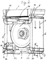
- Fig. 1 shows a variant in which the cooler 2; 6 and 7 of a box-shaped cooler arrangement are connected in series.
- the coolant comes via the inflow line 3z to the connecting piece 12 and enters the collecting tank 5 of the cooler 6 shown on the right. From there it is distributed to the flat tubes 8.1; 8 and flows to the lower header 5 of the same cooler 6.
- This header 5 forms with the header 5 of the lower radiator 2 in the picture an edge 23 of the cooler arrangement, the longitudinal walls 24 of the header 5 in this embodiment having a small distance a , like that Fig. 3 shows.
- the collecting tanks 5 are connected in terms of flow technology at the two lower edges 23 of the cooler arrangement, specifically in the same way as (for example) shown in FIG. 3, which will be described later.
- the center pieces of the peripheral part 30 shown in FIG. 3 can only be seen in the lower right edge 23 in FIG. 1. It can be seen, however, that two fluidic connections 25 are provided between the longitudinal walls of the collecting boxes 5 in this exemplary embodiment. Any number could be provided.
- the same fluidic connection is located in the lower left edge 23. It cannot be seen in FIG. 1.
- the coolant can flow according to the flow arrows 4 shown in the header 5 of the lower cooler 2 , via the flat tubes 8; 8.1 go to the other collecting tank 5 and from there come further into the left cooler 7 in order to leave the cooler arrangement via the drain line 3a, top left.
- 1 shows that a radial fan 10 is arranged in the box-shaped cooler arrangement.
- the flat tubes 8, 8.1 of the coolers 1, 2, 6 and 7 run transversely to the fan axis V.
- the rear of the cooler arrangement is closed by a rear wall R.
- the front has a front wall F with an air inlet opening (not shown) and a nozzle.
- the coolers 2 and 6 are connected in series and the cooler 7 in parallel. Only the reference numerals that were used in the following description were given there. It is clear that the coolers 1, 2, 6 and 7 there also have flat tubes 8; 8.1 and all other necessary features that have been described in FIG. 1.
- In the upper area of the cooler arrangement there is an inflow line 3z which can be plugged together from standard parts, and at the bottom, on the left, there is also an outflow line 3a of the type described in principle in the parent application. However, the arrangement has been changed so that the circuit variant already mentioned is obtained.
- the inlet is located on the top left in FIG. 2.
- FIG. 1 Via the supply line 3z, the cooler 6 and 7 are connected to each other, so that the feed stream splits in the cooler 6 and 7.
- FIG. 2 It enters through the connecting piece 12 in both coolers 6, 7 and their collecting boxes 5 .
- the flow arrows 4 also show how the arrangement is flowed through.
- the right edge 23, which is formed by a collecting tank 5 of the coolers 6 and 2 there are the fluidic connections already described in connection with FIG. 1, of which only a part 30 is also recognizable.
- the cooling liquid can therefore flow into the cooler 2 in order to be further cooled there by the cooling air flow generated by the radial fan 10 .
- the design of the inserts 27 and the seals 32 could be modified accordingly for both variants.
- a flange could also be located on the corresponding flow opening 25 .
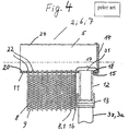
- the variant shown in FIG. 3 has an insert 27 in the corresponding flow openings 25 in the longitudinal walls 24 of both collecting tanks 5 , which consists of a circumferential wall part 28 and an inward and an outward flange 29 .
- the insert 27 is supported in the respective flow opening 25 with one outwardly directed flange 29 and thus provides a suitable soldering surface with the flow opening 25.
- the other inwardly directed flange 29 projects into the collecting box 5 by a small amount.
- This flange 29 serves to receive a peripheral part 30 provided for sealing.
- the peripheral part 30 is equipped with grooves 31 , in which seals 32 are inserted. In the shown, ready-to-use or assembled state, the seals 32 press against the respective wall part 28 of the corresponding insert 30 from the inside , as a result of which the cooling liquid must be prevented from escaping. From FIG. 3 and this description it can also be seen that the fluidic connection contributes significantly to the stability of the cooler arrangement, because the individual coolers have been fixed in their position by this connection.
- the shape of the flow openings 25, the inserts 27 and the peripheral part 30 can be any. In the simplest case, the circular shape is selected.
Landscapes
- Engineering & Computer Science (AREA)
- Physics & Mathematics (AREA)
- Thermal Sciences (AREA)
- Mechanical Engineering (AREA)
- General Engineering & Computer Science (AREA)
- Heat-Exchange Devices With Radiators And Conduit Assemblies (AREA)
- Cooling Or The Like Of Semiconductors Or Solid State Devices (AREA)
- Cooling Or The Like Of Electrical Apparatus (AREA)
- Semiconductor Lasers (AREA)
- Air-Conditioning For Vehicles (AREA)
Applications Claiming Priority (2)
| Application Number | Priority Date | Filing Date | Title |
|---|---|---|---|
| DE2000145987 DE10045987A1 (de) | 2000-08-25 | 2000-09-16 | Kühleranordnung |
| DE10045987 | 2000-09-16 |
Publications (3)
| Publication Number | Publication Date |
|---|---|
| EP1189006A2 true EP1189006A2 (fr) | 2002-03-20 |
| EP1189006A3 EP1189006A3 (fr) | 2003-10-15 |
| EP1189006B1 EP1189006B1 (fr) | 2006-06-14 |
Family
ID=7656544
Family Applications (1)
| Application Number | Title | Priority Date | Filing Date |
|---|---|---|---|
| EP01118936A Expired - Lifetime EP1189006B1 (fr) | 2000-09-16 | 2001-08-04 | Agencement d'un radiateur |
Country Status (4)
| Country | Link |
|---|---|
| US (1) | US6675879B2 (fr) |
| EP (1) | EP1189006B1 (fr) |
| AT (1) | ATE330197T1 (fr) |
| DE (2) | DE10041794A1 (fr) |
Cited By (1)
| Publication number | Priority date | Publication date | Assignee | Title |
|---|---|---|---|---|
| EP1890217A3 (fr) * | 2006-07-25 | 2010-12-08 | Fujitsu Ltd. | Unité de refroidissement de liquides et échangeur de chaleur correspondant |
Families Citing this family (7)
| Publication number | Priority date | Publication date | Assignee | Title |
|---|---|---|---|---|
| DE10041794A1 (de) | 2000-09-16 | 2002-03-07 | Modine Mfg Co | Kühleranordnung und Kühler |
| WO2003106910A1 (fr) * | 2002-06-18 | 2003-12-24 | Showa Denko K.K. | Echangeur thermique de type unite |
| US8002022B2 (en) | 2005-09-16 | 2011-08-23 | Behr Gmbh & Co. Kg | Heat exchanger, in particular exhaust gas heat exchanger for motor vehicles |
| DE102005055482A1 (de) * | 2005-11-18 | 2007-05-24 | Behr Gmbh & Co. Kg | Wärmetauscher für einen Verbrennungsmotor |
| US20140116658A1 (en) * | 2012-10-30 | 2014-05-01 | Deere & Company | Vehicle cooling system |
| US10563925B2 (en) * | 2017-07-12 | 2020-02-18 | Caterpillar Inc. | Cooling assembly for service vehicle |
| FR3090842B1 (fr) * | 2018-12-19 | 2021-01-08 | Valeo Systemes Thermiques | Cadre configuré pour le support d’un échangeur de chaleur |
Citations (1)
| Publication number | Priority date | Publication date | Assignee | Title |
|---|---|---|---|---|
| DE10041794A1 (de) | 2000-09-16 | 2002-03-07 | Modine Mfg Co | Kühleranordnung und Kühler |
Family Cites Families (20)
| Publication number | Priority date | Publication date | Assignee | Title |
|---|---|---|---|---|
| US623348A (en) * | 1899-04-18 | Fan-blower heating apparatus | ||
| US4062401A (en) * | 1976-05-03 | 1977-12-13 | International Harvester Company | Toroidal multifluid segmented heat exchanger |
| DE2951352C2 (de) * | 1979-12-20 | 1982-10-28 | Dieter Christian 9050 Steinegg-Appenzell Steeb | Flachrohr-Wärmetauscher |
| US4565075A (en) * | 1984-06-08 | 1986-01-21 | Carrier Corporation | Polygon fan coil cabinet and method of assembly |
| FR2588365A1 (fr) * | 1985-10-03 | 1987-04-10 | Valeo | Echangeur de chaleur, en particulier pour vehicule automobile |
| JP3036892B2 (ja) * | 1991-06-14 | 2000-04-24 | 昭和アルミニウム株式会社 | 熱交換器 |
| DE4139104C1 (fr) * | 1991-11-28 | 1993-05-27 | Mtu Muenchen Gmbh | |
| DE4205234C2 (de) * | 1992-02-21 | 1994-11-24 | Daimler Benz Ag | Wärmetauscher, insbesondere für Kraftfahrzeuge |
| DE4212070A1 (de) * | 1992-04-10 | 1993-10-14 | Laengerer & Reich Gmbh & Co | Wärmeaustauscher, insbesondere Kühler, z. B. Ölkühler |
| US5348081A (en) * | 1993-10-12 | 1994-09-20 | General Motors Corporation | High capacity automotive condenser |
| US5445218A (en) * | 1994-02-22 | 1995-08-29 | Nieh; Sen | Compact heat exchanger |
| DE29504867U1 (de) * | 1995-03-08 | 1996-07-11 | Liebherr-Werk Bischofshofen Ges.M.B.H., Bischofshofen | Kühleranordnung für ein Kraftfahrzeug, eine Baumaschine oder eine Erdbewegungsmaschine |
| DE19527050C2 (de) * | 1995-07-25 | 2003-04-24 | Modine Mfg Co | Wärmetauscher für Kraftfahrzeuge |
| DE19713712C1 (de) * | 1997-04-03 | 1998-04-16 | Laengerer & Reich Gmbh & Co | Radialventilator, insbesonders als Lüfter für die Kühlanlage eines Kraftfahrzeuges |
| DE19724728C2 (de) * | 1997-06-12 | 2003-01-30 | Modine Mfg Co | Kühleranordnung und luftgekühlter Kühler |
| DE19828362B4 (de) * | 1998-06-25 | 2009-07-09 | Behr Gmbh & Co. Kg | Lüfterhaube für eine Wärmeübertrageranordnung eines Kraftfahrzeugs |
| US6145479A (en) * | 1999-02-18 | 2000-11-14 | Kohler Co. | Vertical shaft engine cooling apparatus |
| EP1045217B1 (fr) * | 1999-04-16 | 2003-03-26 | Modine Manufacturing Company | Système de refroidissement |
| US6129056A (en) * | 1999-08-23 | 2000-10-10 | Case Corporation | Cooling system for work vehicle |
| DE19950755A1 (de) * | 1999-10-21 | 2001-04-26 | Modine Mfg Co | Kühlanlage III |
-
2000
- 2000-08-25 DE DE10041794A patent/DE10041794A1/de not_active Withdrawn
-
2001
- 2001-08-04 DE DE50110126T patent/DE50110126D1/de not_active Expired - Lifetime
- 2001-08-04 EP EP01118936A patent/EP1189006B1/fr not_active Expired - Lifetime
- 2001-08-04 AT AT01118936T patent/ATE330197T1/de not_active IP Right Cessation
- 2001-08-14 US US09/929,387 patent/US6675879B2/en not_active Expired - Fee Related
Patent Citations (1)
| Publication number | Priority date | Publication date | Assignee | Title |
|---|---|---|---|---|
| DE10041794A1 (de) | 2000-09-16 | 2002-03-07 | Modine Mfg Co | Kühleranordnung und Kühler |
Cited By (1)
| Publication number | Priority date | Publication date | Assignee | Title |
|---|---|---|---|---|
| EP1890217A3 (fr) * | 2006-07-25 | 2010-12-08 | Fujitsu Ltd. | Unité de refroidissement de liquides et échangeur de chaleur correspondant |
Also Published As
| Publication number | Publication date |
|---|---|
| DE50110126D1 (de) | 2006-07-27 |
| EP1189006A3 (fr) | 2003-10-15 |
| ATE330197T1 (de) | 2006-07-15 |
| US6675879B2 (en) | 2004-01-13 |
| US20020033248A1 (en) | 2002-03-21 |
| DE10041794A1 (de) | 2002-03-07 |
| EP1189006B1 (fr) | 2006-06-14 |
Similar Documents
| Publication | Publication Date | Title |
|---|---|---|
| EP0632245B1 (fr) | Echangeur de chaleur eau-air en aluminium pour véhicules automobiles | |
| EP2044304B1 (fr) | Échangeur de chaleur avec raccord d'accouplement, par exemple refroidisseur d'air de charge, et raccord d'accouplement pour échangeur de chaleur | |
| DE3311579C2 (de) | Wärmetauscher | |
| DE3855049T2 (de) | Wärmetauscher für einen Kühlturm | |
| DE69611507T2 (de) | Verflüssiger mit einbezogenem behälter für klimaanlage eines kraftfahrzeuges | |
| DE3720483A1 (de) | Waermetauscher | |
| DE10014484A1 (de) | Wärmetauscher mit Sammelbehälter | |
| EP1273864B1 (fr) | Echangeur de chaleur | |
| DE10329297A1 (de) | Kondensatoraggregat mit leicht veränderbarer Volumetrie | |
| EP1306638A2 (fr) | Echangeur de chaleur à plaques sans carter | |
| DE4403144C2 (de) | Plattenwärmeaustauscher | |
| DE10149507A1 (de) | Wärmetauscher, insbesondere Flachrohr-Wärmetauscher eines Kraftfahrzeugs | |
| DE3142028A1 (de) | Oelkuehler | |
| DE3440064A1 (de) | Oelkuehler | |
| EP1189006A2 (fr) | Agencement d'un radiateur | |
| DE102007010530B4 (de) | Behälter für einen Wärmetauscher und Wärmetauscher | |
| DE69100704T2 (de) | Endkammer mit Ausdehnungsgefäss für einen Wärmetauscher, zum Beispiel einen Kühler und Wärmetauscher mit einer derartigen Vorrichtung. | |
| EP2336697B1 (fr) | Echangeur thermique avec des éléments extrudés et empilés | |
| DE19830846B4 (de) | Wärmetauscher | |
| DE19746371A1 (de) | Wärmetauscher mit einem Sammelkasten mit zwei aneinander angrenzenden Kammern | |
| EP1182414B1 (fr) | Système de refroidissement | |
| DE10045987A1 (de) | Kühleranordnung | |
| DE2840813B1 (de) | Kuehler mit vertikalen Kuehlrohren und einer Entlueftungseinrichtung | |
| EP0893667B1 (fr) | Echangeur de chaleur à plaques,sans caisson | |
| DE3136374C2 (de) | Kältemittelverdampfer, insbesondere für Klimaanlagen in Kraftfahrzeugen |
Legal Events
| Date | Code | Title | Description |
|---|---|---|---|
| PUAI | Public reference made under article 153(3) epc to a published international application that has entered the european phase |
Free format text: ORIGINAL CODE: 0009012 |
|
| AK | Designated contracting states |
Kind code of ref document: A2 Designated state(s): AT BE CH CY DE DK ES FI FR GB GR IE IT LI LU MC NL PT SE TR |
|
| AX | Request for extension of the european patent |
Free format text: AL;LT;LV;MK;RO;SI |
|
| PUAL | Search report despatched |
Free format text: ORIGINAL CODE: 0009013 |
|
| AK | Designated contracting states |
Kind code of ref document: A3 Designated state(s): AT BE CH CY DE DK ES FI FR GB GR IE IT LI LU MC NL PT SE TR |
|
| AX | Request for extension of the european patent |
Extension state: AL LT LV MK RO SI |
|
| 17P | Request for examination filed |
Effective date: 20040415 |
|
| AKX | Designation fees paid |
Designated state(s): AT BE CH CY DE DK ES FI FR GB GR IE IT LI LU MC NL PT SE TR |
|
| GRAP | Despatch of communication of intention to grant a patent |
Free format text: ORIGINAL CODE: EPIDOSNIGR1 |
|
| GRAS | Grant fee paid |
Free format text: ORIGINAL CODE: EPIDOSNIGR3 |
|
| GRAA | (expected) grant |
Free format text: ORIGINAL CODE: 0009210 |
|
| AK | Designated contracting states |
Kind code of ref document: B1 Designated state(s): AT BE CH CY DE DK ES FI FR GB GR IE IT LI LU MC NL PT SE TR |
|
| PG25 | Lapsed in a contracting state [announced via postgrant information from national office to epo] |
Ref country code: IT Free format text: LAPSE BECAUSE OF FAILURE TO SUBMIT A TRANSLATION OF THE DESCRIPTION OR TO PAY THE FEE WITHIN THE PRESCRIBED TIME-LIMIT;WARNING: LAPSES OF ITALIAN PATENTS WITH EFFECTIVE DATE BEFORE 2007 MAY HAVE OCCURRED AT ANY TIME BEFORE 2007. THE CORRECT EFFECTIVE DATE MAY BE DIFFERENT FROM THE ONE RECORDED. Effective date: 20060614 Ref country code: IE Free format text: LAPSE BECAUSE OF FAILURE TO SUBMIT A TRANSLATION OF THE DESCRIPTION OR TO PAY THE FEE WITHIN THE PRESCRIBED TIME-LIMIT Effective date: 20060614 Ref country code: FI Free format text: LAPSE BECAUSE OF FAILURE TO SUBMIT A TRANSLATION OF THE DESCRIPTION OR TO PAY THE FEE WITHIN THE PRESCRIBED TIME-LIMIT Effective date: 20060614 Ref country code: NL Free format text: LAPSE BECAUSE OF FAILURE TO SUBMIT A TRANSLATION OF THE DESCRIPTION OR TO PAY THE FEE WITHIN THE PRESCRIBED TIME-LIMIT Effective date: 20060614 |
|
| REG | Reference to a national code |
Ref country code: GB Ref legal event code: FG4D Free format text: NOT ENGLISH |
|
| REG | Reference to a national code |
Ref country code: CH Ref legal event code: EP |
|
| REG | Reference to a national code |
Ref country code: IE Ref legal event code: FG4D Free format text: LANGUAGE OF EP DOCUMENT: GERMAN |
|
| REF | Corresponds to: |
Ref document number: 50110126 Country of ref document: DE Date of ref document: 20060727 Kind code of ref document: P |
|
| PG25 | Lapsed in a contracting state [announced via postgrant information from national office to epo] |
Ref country code: BE Free format text: LAPSE BECAUSE OF NON-PAYMENT OF DUE FEES Effective date: 20060831 Ref country code: MC Free format text: LAPSE BECAUSE OF NON-PAYMENT OF DUE FEES Effective date: 20060831 Ref country code: LI Free format text: LAPSE BECAUSE OF NON-PAYMENT OF DUE FEES Effective date: 20060831 Ref country code: CH Free format text: LAPSE BECAUSE OF NON-PAYMENT OF DUE FEES Effective date: 20060831 |
|
| PG25 | Lapsed in a contracting state [announced via postgrant information from national office to epo] |
Ref country code: SE Free format text: LAPSE BECAUSE OF FAILURE TO SUBMIT A TRANSLATION OF THE DESCRIPTION OR TO PAY THE FEE WITHIN THE PRESCRIBED TIME-LIMIT Effective date: 20060914 Ref country code: DK Free format text: LAPSE BECAUSE OF FAILURE TO SUBMIT A TRANSLATION OF THE DESCRIPTION OR TO PAY THE FEE WITHIN THE PRESCRIBED TIME-LIMIT Effective date: 20060914 |
|
| PG25 | Lapsed in a contracting state [announced via postgrant information from national office to epo] |
Ref country code: ES Free format text: LAPSE BECAUSE OF FAILURE TO SUBMIT A TRANSLATION OF THE DESCRIPTION OR TO PAY THE FEE WITHIN THE PRESCRIBED TIME-LIMIT Effective date: 20060925 |
|
| GBT | Gb: translation of ep patent filed (gb section 77(6)(a)/1977) |
Effective date: 20060923 |
|
| PG25 | Lapsed in a contracting state [announced via postgrant information from national office to epo] |
Ref country code: PT Free format text: LAPSE BECAUSE OF FAILURE TO SUBMIT A TRANSLATION OF THE DESCRIPTION OR TO PAY THE FEE WITHIN THE PRESCRIBED TIME-LIMIT Effective date: 20061114 |
|
| NLV1 | Nl: lapsed or annulled due to failure to fulfill the requirements of art. 29p and 29m of the patents act | ||
| ET | Fr: translation filed | ||
| REG | Reference to a national code |
Ref country code: IE Ref legal event code: FD4D |
|
| REG | Reference to a national code |
Ref country code: CH Ref legal event code: PL |
|
| PLBE | No opposition filed within time limit |
Free format text: ORIGINAL CODE: 0009261 |
|
| STAA | Information on the status of an ep patent application or granted ep patent |
Free format text: STATUS: NO OPPOSITION FILED WITHIN TIME LIMIT |
|
| 26N | No opposition filed |
Effective date: 20070315 |
|
| PG25 | Lapsed in a contracting state [announced via postgrant information from national office to epo] |
Ref country code: AT Free format text: LAPSE BECAUSE OF NON-PAYMENT OF DUE FEES Effective date: 20060804 |
|
| BERE | Be: lapsed |
Owner name: MODINE MANUFACTURING CY Effective date: 20060831 |
|
| PG25 | Lapsed in a contracting state [announced via postgrant information from national office to epo] |
Ref country code: GR Free format text: LAPSE BECAUSE OF FAILURE TO SUBMIT A TRANSLATION OF THE DESCRIPTION OR TO PAY THE FEE WITHIN THE PRESCRIBED TIME-LIMIT Effective date: 20060915 |
|
| PG25 | Lapsed in a contracting state [announced via postgrant information from national office to epo] |
Ref country code: TR Free format text: LAPSE BECAUSE OF FAILURE TO SUBMIT A TRANSLATION OF THE DESCRIPTION OR TO PAY THE FEE WITHIN THE PRESCRIBED TIME-LIMIT Effective date: 20060614 Ref country code: LU Free format text: LAPSE BECAUSE OF NON-PAYMENT OF DUE FEES Effective date: 20060804 |
|
| PG25 | Lapsed in a contracting state [announced via postgrant information from national office to epo] |
Ref country code: CY Free format text: LAPSE BECAUSE OF FAILURE TO SUBMIT A TRANSLATION OF THE DESCRIPTION OR TO PAY THE FEE WITHIN THE PRESCRIBED TIME-LIMIT Effective date: 20060614 |
|
| PGFP | Annual fee paid to national office [announced via postgrant information from national office to epo] |
Ref country code: DE Payment date: 20140902 Year of fee payment: 14 |
|
| PGFP | Annual fee paid to national office [announced via postgrant information from national office to epo] |
Ref country code: FR Payment date: 20140822 Year of fee payment: 14 Ref country code: GB Payment date: 20140826 Year of fee payment: 14 |
|
| REG | Reference to a national code |
Ref country code: DE Ref legal event code: R119 Ref document number: 50110126 Country of ref document: DE |
|
| GBPC | Gb: european patent ceased through non-payment of renewal fee |
Effective date: 20150804 |
|
| REG | Reference to a national code |
Ref country code: FR Ref legal event code: ST Effective date: 20160429 |
|
| PG25 | Lapsed in a contracting state [announced via postgrant information from national office to epo] |
Ref country code: DE Free format text: LAPSE BECAUSE OF NON-PAYMENT OF DUE FEES Effective date: 20160301 Ref country code: GB Free format text: LAPSE BECAUSE OF NON-PAYMENT OF DUE FEES Effective date: 20150804 |
|
| PG25 | Lapsed in a contracting state [announced via postgrant information from national office to epo] |
Ref country code: FR Free format text: LAPSE BECAUSE OF NON-PAYMENT OF DUE FEES Effective date: 20150831 |