EP1189116A2 - Rollvorrichtung für Bildübertragungsvorrichtung - Google Patents
Rollvorrichtung für Bildübertragungsvorrichtung Download PDFInfo
- Publication number
- EP1189116A2 EP1189116A2 EP01121766A EP01121766A EP1189116A2 EP 1189116 A2 EP1189116 A2 EP 1189116A2 EP 01121766 A EP01121766 A EP 01121766A EP 01121766 A EP01121766 A EP 01121766A EP 1189116 A2 EP1189116 A2 EP 1189116A2
- Authority
- EP
- European Patent Office
- Prior art keywords
- roller
- shaft
- bearing
- lug
- image
- Prior art date
- Legal status (The legal status is an assumption and is not a legal conclusion. Google has not performed a legal analysis and makes no representation as to the accuracy of the status listed.)
- Granted
Links
Images


Classifications
-
- G—PHYSICS
- G03—PHOTOGRAPHY; CINEMATOGRAPHY; ANALOGOUS TECHNIQUES USING WAVES OTHER THAN OPTICAL WAVES; ELECTROGRAPHY; HOLOGRAPHY
- G03G—ELECTROGRAPHY; ELECTROPHOTOGRAPHY; MAGNETOGRAPHY
- G03G15/00—Apparatus for electrographic processes using a charge pattern
- G03G15/14—Apparatus for electrographic processes using a charge pattern for transferring a pattern to a second base
- G03G15/16—Apparatus for electrographic processes using a charge pattern for transferring a pattern to a second base of a toner pattern, e.g. a powder pattern, e.g. magnetic transfer
- G03G15/1665—Apparatus for electrographic processes using a charge pattern for transferring a pattern to a second base of a toner pattern, e.g. a powder pattern, e.g. magnetic transfer by introducing the second base in the nip formed by the recording member and at least one transfer member, e.g. in combination with bias or heat
- G03G15/167—Apparatus for electrographic processes using a charge pattern for transferring a pattern to a second base of a toner pattern, e.g. a powder pattern, e.g. magnetic transfer by introducing the second base in the nip formed by the recording member and at least one transfer member, e.g. in combination with bias or heat at least one of the recording member or the transfer member being rotatable during the transfer
-
- F—MECHANICAL ENGINEERING; LIGHTING; HEATING; WEAPONS; BLASTING
- F16—ENGINEERING ELEMENTS AND UNITS; GENERAL MEASURES FOR PRODUCING AND MAINTAINING EFFECTIVE FUNCTIONING OF MACHINES OR INSTALLATIONS; THERMAL INSULATION IN GENERAL
- F16C—SHAFTS; FLEXIBLE SHAFTS; ELEMENTS OR CRANKSHAFT MECHANISMS; ROTARY BODIES OTHER THAN GEARING ELEMENTS; BEARINGS
- F16C13/00—Rolls, drums, discs, or the like; Bearings or mountings therefor
- F16C13/02—Bearings
-
- F—MECHANICAL ENGINEERING; LIGHTING; HEATING; WEAPONS; BLASTING
- F16—ENGINEERING ELEMENTS AND UNITS; GENERAL MEASURES FOR PRODUCING AND MAINTAINING EFFECTIVE FUNCTIONING OF MACHINES OR INSTALLATIONS; THERMAL INSULATION IN GENERAL
- F16C—SHAFTS; FLEXIBLE SHAFTS; ELEMENTS OR CRANKSHAFT MECHANISMS; ROTARY BODIES OTHER THAN GEARING ELEMENTS; BEARINGS
- F16C33/00—Parts of bearings; Special methods for making bearings or parts thereof
- F16C33/02—Parts of sliding-contact bearings
- F16C33/04—Brasses; Bushes; Linings
- F16C33/20—Sliding surface consisting mainly of plastics
-
- F—MECHANICAL ENGINEERING; LIGHTING; HEATING; WEAPONS; BLASTING
- F16—ENGINEERING ELEMENTS AND UNITS; GENERAL MEASURES FOR PRODUCING AND MAINTAINING EFFECTIVE FUNCTIONING OF MACHINES OR INSTALLATIONS; THERMAL INSULATION IN GENERAL
- F16C—SHAFTS; FLEXIBLE SHAFTS; ELEMENTS OR CRANKSHAFT MECHANISMS; ROTARY BODIES OTHER THAN GEARING ELEMENTS; BEARINGS
- F16C2208/00—Plastics; Synthetic resins, e.g. rubbers
- F16C2208/20—Thermoplastic resins
- F16C2208/66—Acetals, e.g. polyoxymethylene [POM]
Definitions
- the present invention relates to a copier, printer, facsimile apparatus or similar electrophotographic image forming apparatus and more particularly to a roller device for a contact type image transferring device.
- a contact type image transferring device is extensively used for an electrophotographic image forming apparatus because it does not produce nitrogen oxides or similar toxic components and because it is operable with a low voltage and therefore cost effective. These advantages are not achievable with a corona discharge type image transferring device.
- the contact type image transferring device includes a roller device including an image transfer roller. The image transfer roller is pressed against a photoconductive drum in such a manner as to be movable substantially perpendicularly to the axis of the drum. The roller rotates while absorbing the thickness of a paper sheet or similar recording medium being conveyed as well as the eccentricity of the roller and drum. For this purpose, compression springs exert a preselected load on bearings that support opposite ends of the roller. The roller must be replaced when it wears due to aging or is contaminated in order to maintain the expected image transferring ability and conveying ability.
- Japanese Patent Laid-Open Publication Nos. 5-333721 and 9-138590 each propose a semicircular bearing formed with an opening and simple means for preventing a shaft from slipping out of the bearing.
- this bearing may facilitate the replacement of an image transfer roller, carrier and toner particles, as well as other impurities, are apt to enter the bearing and produce noise while increasing resistance to rotation.
- Japanese Patent Laid-Open Publication No. 11-93940 discloses a similar arrangement, it needs extra means for locking and unlocking a color that prevents the shaft of a roller from slipping out.
- a roller device of the present invention includes a roller including a shaft, a bearing for rotatably supporting the shaft, a pressing device for pressing the bearing, and a lug protruding from the bearing in the axial direction of the roller.
- the pressing device is implemented as a pair of hook members deformable away from each other in a direction perpendicular to the axis of the roller.
- An image transferring device including the above roller device and an image forming apparatus including the image transferring device are also disclosed.
- the image transfer roller device includes an image transfer roller 10 and a bearing 12 rotatably supporting the roller 10.
- a spring 16 presses the bearing 12 such that the roller 10 is pressed against a photoconductive element not shown.
- a pair of hook members 14 restrict the movement of the bearing 12 in the up-and-down direction and are formed of resin. More specifically, each hook member 14 includes a catch 14a for preventing the bearing 12 from slipping out.
- the hook members 14 have a problem that while they must be rigid enough to retain the bearing 12, they make it difficult to attach and detach the bearing 12 and sometimes damage it if excessively rigid. Another problem is that resin forming the hook members 14 deforms due to aging and causes the bearing 12 and roller 10 to easily slip out. This is also true when the catches 14a of the hook members 14 wear due to repeated attachment and detachment.
- a driving force acts on the roller 10 via gears, not shown, during operation with the result that a force acts on the roller 10 in a direction perpendicular to the axis of the roller 10 as well. It follows that if the rigidity of the hookmembers 14 is short, the photoconductive drum and transfer roller 10 are brought out of parallelism, causing a paper sheet or similar recording medium to skew.
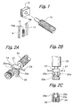
- FIGS. 2A through 2C show another conventional image transfer roller device addressing the above-described problems.
- the image transfer roller device includes an image transfer roller 20 and a bearing 22 rotatably supporting the roller 20.
- a pair of ribs 24 allow the bearing 22 to move only in one direction.
- a spring 28 presses the bearing 22 such that the roller 20 is pressed against a photoconductive element not shown.
- a problem with both of the conventional configurations described above is that carrier and toner particles, as well as other impurities, enter the bearing, which supports the image transfer roller, producing noise. Moreover, toner and carrier particles scattered around the photoconductive element and a developing section are likely to deposit on the image transfer roller and then enter the bearing.
- the image forming apparatus includes a photoconductive element implemented as a drum 40, which is formed of OPC (Organic PhotoConductor) or similar photoconductive substance. While the drum 40 is rotated counterclockwise, as viewed in FIG. 3, a charge roller 42 applied with a high-tension voltage uniformly charges the surface of the drum 40.
- a scanner 44 scans the surface of a document and outputs an image signal representative of a document image.
- An optical writing unit 46 scans the charged surface of the drum 40 with a laser beam L in accordance with the image signal, thereby forming a latent image on the drum 40.
- a developing unit 48 includes a sleeve 48a for development and stores a toner and carrier mixture.
- the carrier forms a magnet brush on the sleeve 48a. While the sleeve 48a is in rotation, the toner is transferred from the magnet brush to the latent image on the drum 40 to thereby produce a corresponding toner image.
- the drum 40 in rotation conveys the toner image to a nip between the drum 40 and an image transfer roller 50.
- a pickup roller 52 pays out a paper sheet or similar recording medium 54 toward a registration roller pair 53.
- the registration roller pair 53 stops the paper sheet 54 and then drives it such that the leading edge of the paper sheet 54 meets the leading edge of the toner image formed on the drum 40.
- a bias for image transfer is applied to the roller 50 and charges the roller 50 to polarity opposite to the polarity of the toner deposited on the drum 40. Consequently, the toner image is transferred from the drum 40 to the paper sheet 54.
- a peeler 56 peels off the paper sheet 54 from the drum 40.
- the peeler 51 is applied with a bias voltage or connected to ground.
- a cleaning blade 56 removes the toner left on the paper sheet 54 after image transfer.
- a conveyor not shown, returns such toner to the sleeve 48a.
- a quenching lamp or discharge lamp 58 discharges the entire surface of the drum 40 with light to thereby prepare the drum 40 for the next image formation.
- the peeler 51 discharges the paper sheet 54 carrying the toner image thereon.
- a heat roller 60 fixes the toner image on the paper sheet 54 with heat.
- an outlet roller pair 62 drives the paper sheet 54 out of the apparatus.
- the right wall of the apparatus is partly openable. By opening this wall, the operator of the apparatus is capable of accessing a path between the image transfer roller 50 and the drum 40 in order to remove a jamming paper sheet. Also, the operator can replace the image transfer roller 50 by opening the above wall.
- FIGS . 4A through 4D show an arrangement for rotatably supporting the image transfer roller 50 (roller 50 hereinafter) in detail.
- a bearing 70 rotatably supports the roller 50 and includes two lugs 70a extending in the axial direction of the roller 50.
- the bearing 70 is formed of POM (polyacetal, polyoxymethylene or Polyformaldehyde) resin or similar resin.
- Another bearing, not shown, positioned at the other end of the roller 50 is formed of conductive POM or similar conductive resin, so that a bias for image transfer can be applied to the roller 50.
- a spring 72 constantly biases the bearing 70 with a preselected force.
- a pair of ribs 74 allow the bearing 70 to slide in only one direction, as in the conventional arrangement.
- the spring 72 presses the roller 50 against the photoconductive drum 40 via the bearing 70.
- a gear, not shown, associated with the drum 40 causes the roller 50 to rotate via a gear/roller 76.
- the gear/roller 76 maintains the amount of bite of the roller 50 into the drum 40 constant. In this condition, the roller 50 conveys the paper sheet 54.
- a pair of elastic hook members 80 are formed of ABS (Acrylonitrile Butadien Styrene terpolymer), PC (Poly Carbonate) or similar resin.
- the free end of the hook members 80, i.e., catches 80a are elastically deformable in a direction perpendicular to the axis of the roller 50.
- the two lugs 70a of the bearing 70 respectively abut against the catches 80a of the hook members 80, preventing the bearing 70 and roller 50 from slipping out.
- the roller 50 is held stationary at a preselected position more accurately than in the conventional configuration. Further, the hook members 80 are prevented from deforming due to aging and causing the roller 50 to slip out.
- the hook members 80 can therefore serve the expected function with lower rigidity than the conventional hook members. This allows a person to easily remove the bearing 70 and roller 50 by forcing the hook members 80 away from each other by fingers.
- FIGS. 5A through 5C show a positional relation between the lugs 70a and the catches 80a of the hook members 80.
- the lugs 70b each include an inclined surface 70b lying on a line that is tangential to the roller 50. Assume that an angle between a vertical line and the inclined surface 70b is ⁇ ', and that an angle between a vertical line and the inclined surface of each catch 80a is ⁇ . Then, there holds a relation of ⁇ ' ⁇ ⁇ . This relation allows the shaft 50a of the roller 50 to be smoothly inserted between the catches 80a.
- the gap between the circumference of the shaft 50a and each lug 70a should preferably be 0 mm to 0.5 mm. In the illustrative embodiment, the gap is selected to be 0.3 mm. As shown in FIG. 6, when impurities 82 accumulate on the shaft 50a of the roller 50, the above gap prevents the impurities 82 from entering the bearing 70 in cooperation with the inclined ridge of the lug 70a, which will be described hereinafter.
- each lug 70a that faces the shaft 50a is inclined by an angle of ⁇ a with respect to the axis of the roller 50 in the circumferential direction of the roller 50.
- the angle ⁇ a is greater than zero and selected to be 3 degrees in the illustrative embodiment.
- toner, carrier and other impurities deposited on the shaft 50a are guided by the inclined ridge of the lug 27a away from the bearing 70. This prevents the impurities from entering the bearing 82 and producing noise.
- the inclined ridge is positioned at both sides of the bearing 70 although it may be positioned at one side of the same.
- a magnetic piece 84 is positioned between each lug 70a and the shaft 50a and spaced from the shaft 50a.
- the magnetic piece 84 magnetically collects the carrier deposited on the shaft 50a and prevents it from flying about.
- the toner deposits on the carrier collected by the magnetic piece 84.
- the magnetic piece 84 therefore insures a cleaning effect over a long period of time.
- the lug 70a itself may be formed of a magnetic material, if desired. Further, the magnetic piece 84 may be replaced with, e.g., a piece of foam sponge or felt.
- the present invention provides a roller device capable of facilitating the attachment and detachment of a roller with a simple configuration, accurately positioning the roller, and preventing the roller from slipping out due to aging or the deformation of hook members. Further, lugs protruding from a bearing clean the shaft of the roller and thereby prevents impurities from entering the bearing and producing noise.
- the present invention relates to a roller device, an image transferring device (in particular an image transfer roller) and an image forming apparatus (e.g. a copier, facsimile apparatus, printer, etc.), in particular an electrophotographic image forming apparatus.
- an image transferring device in particular an image transfer roller
- an image forming apparatus e.g. a copier, facsimile apparatus, printer, etc.
- the roller and the bearing for the shaft of the roller is displaceable in the direction in which it is pressed by the pressing means.
- a guide (74) for guiding the bearing in the pressing direction in particular such that the bearing is not displaced perpendicular to the pressing direction.
- the hook members are deformable in a direction perpendicular to the pressing direction.
- the ends of the hook member (catches) are more elastic than the remaining part of the hook member.
- the lug is constituted such that it faces the surface of the shaft which is not covered by the bearing and such that the shaft is freely rotatable, in particular due to a gap between the lug and the shaft.
- the lug is disposed such that it is at least partially arranged between at least parts of the hook member and the shaft.
- the lugs are arranged at both sides of the bearing.
- the lug is integrally with the bearing or contacts the bearing.
- the lug surrounds at least partially the surface of the shaft.
- the lug faces the surface of the shaft at two opposing sides of the shaft.
- the lug is constituted such that the distance between the afore-mentioned two sides of the lug increases in an axial direction of the shaft away from the roller.
- the afore-mentioned increase is in particular at that side of the lug which faces or contacts the catches of the hook member.
- the hook member there is at least for a part of the hook member a form-fit between the lug and the hook member.
- that side of the lug which is directed to the catches or which faces the catches is formed such that it blocks a movement of the roller in pressing direction if the lug contacts the catches.
Landscapes
- Engineering & Computer Science (AREA)
- General Engineering & Computer Science (AREA)
- Mechanical Engineering (AREA)
- Physics & Mathematics (AREA)
- General Physics & Mathematics (AREA)
- Electrostatic Charge, Transfer And Separation In Electrography (AREA)
- Delivering By Means Of Belts And Rollers (AREA)
- Paper Feeding For Electrophotography (AREA)
- Feeding Of Articles By Means Other Than Belts Or Rollers (AREA)
- Rolls And Other Rotary Bodies (AREA)
- Mounting Of Bearings Or Others (AREA)
- Electrophotography Configuration And Component (AREA)
Applications Claiming Priority (2)
| Application Number | Priority Date | Filing Date | Title |
|---|---|---|---|
| JP2000283982A JP4102011B2 (ja) | 2000-09-19 | 2000-09-19 | 転写ローラ装置 |
| JP2000283982 | 2000-09-19 |
Publications (3)
| Publication Number | Publication Date |
|---|---|
| EP1189116A2 true EP1189116A2 (de) | 2002-03-20 |
| EP1189116A3 EP1189116A3 (de) | 2002-05-15 |
| EP1189116B1 EP1189116B1 (de) | 2005-05-11 |
Family
ID=18768267
Family Applications (1)
| Application Number | Title | Priority Date | Filing Date |
|---|---|---|---|
| EP01121766A Expired - Lifetime EP1189116B1 (de) | 2000-09-19 | 2001-09-19 | Rollvorrichtung für Bildübertragungsvorrichtung |
Country Status (4)
| Country | Link |
|---|---|
| US (1) | US6601991B2 (de) |
| EP (1) | EP1189116B1 (de) |
| JP (1) | JP4102011B2 (de) |
| DE (1) | DE60110704T2 (de) |
Cited By (2)
| Publication number | Priority date | Publication date | Assignee | Title |
|---|---|---|---|---|
| EP1643141A1 (de) * | 2004-09-30 | 2006-04-05 | Profilati S.p.A. | Trägeranordnung für Förderrollen |
| EP1841973A4 (de) * | 2005-01-25 | 2008-03-05 | Gcc Ip Pty Ltd | Führungslagerbefestigung für ein drehbares element und diese enthaltende entwicklungswalze |
Families Citing this family (18)
| Publication number | Priority date | Publication date | Assignee | Title |
|---|---|---|---|---|
| JP3710129B2 (ja) * | 2002-09-04 | 2005-10-26 | 株式会社リコー | 画像形成装置及び転写ユニット |
| US7085528B2 (en) * | 2002-12-03 | 2006-08-01 | Ricoh Company, Ltd. | Cleaning unit, process cartridge, and image forming apparatus |
| EP1452931A1 (de) * | 2003-02-28 | 2004-09-01 | Ricoh Company, Ltd. | Bildformungsapparat mit einsetzbarer Prozesskartusche |
| CN100349073C (zh) * | 2003-03-05 | 2007-11-14 | 株式会社理光 | 图像形成装置及处理卡盒 |
| JP4165817B2 (ja) * | 2003-04-10 | 2008-10-15 | 株式会社リコー | 画像形成装置及びこれに用いられるプロセスカートリッジ |
| JP2004334092A (ja) * | 2003-05-12 | 2004-11-25 | Ricoh Co Ltd | クリーニング装置、プロセスカートリッジ、画像形成装置、及びこれらに用いるトナー |
| JP2005017463A (ja) * | 2003-06-24 | 2005-01-20 | Ricoh Co Ltd | 画像形成装置及びこれに用いられるプロセスカートリッジ、トナー |
| JP2005024665A (ja) | 2003-06-30 | 2005-01-27 | Ricoh Co Ltd | 粉体搬送装置、画像形成装置、トナー収容部及びプロセスカートリッジ |
| JP2005301216A (ja) * | 2004-03-19 | 2005-10-27 | Ricoh Co Ltd | 画像形成装置およびプロセスカートリッジ |
| TWI248757B (en) * | 2004-07-05 | 2006-02-01 | Avision Inc | Automatic document feeder having a replaceable friction roller assembly |
| EP1842104A1 (de) * | 2005-01-25 | 2007-10-10 | GCC IP Pty Limited | Halteglied für ein drehbares element |
| JP2007031027A (ja) * | 2005-07-25 | 2007-02-08 | Kyocera Mita Corp | 用紙搬送装置 |
| JP4689408B2 (ja) * | 2005-08-19 | 2011-05-25 | 株式会社リコー | 軸受保持構造、現像装置、プロセスカートリッジ、および画像形成装置 |
| KR100667831B1 (ko) * | 2005-11-10 | 2007-01-11 | 삼성전자주식회사 | 로킹 유니트를 구비한 화상형성장치 |
| JP4569516B2 (ja) * | 2006-05-11 | 2010-10-27 | 富士ゼロックス株式会社 | 保持部材、これを備えた搬送装置、及びこれを備えた画像形成装置 |
| JP6874327B2 (ja) * | 2016-10-28 | 2021-05-19 | ブラザー工業株式会社 | 印刷装置 |
| JP6693580B2 (ja) * | 2019-01-08 | 2020-05-13 | ブラザー工業株式会社 | 画像形成装置 |
| WO2020188720A1 (ja) * | 2019-03-18 | 2020-09-24 | 株式会社Pfu | 媒体搬送装置 |
Family Cites Families (8)
| Publication number | Priority date | Publication date | Assignee | Title |
|---|---|---|---|---|
| JPH045676A (ja) * | 1990-04-13 | 1992-01-09 | Ricoh Co Ltd | 画像形成装置 |
| JP3040525B2 (ja) * | 1990-11-30 | 2000-05-15 | 株式会社リコー | 画像形成装置 |
| JPH0664279A (ja) | 1992-08-21 | 1994-03-08 | Canon Inc | レーザビームプリンタ及びその付属部材 |
| JP3349256B2 (ja) * | 1994-04-26 | 2002-11-20 | 株式会社リコー | 転写ベルト装置 |
| JPH08160781A (ja) | 1994-12-12 | 1996-06-21 | Ricoh Co Ltd | 画像形成装置 |
| US5709481A (en) * | 1996-04-29 | 1998-01-20 | Hewlett-Packard Company | Apparatus for creating back tension in a printer/plotter system |
| JP3703987B2 (ja) * | 1999-02-25 | 2005-10-05 | 株式会社リコー | 転写装置及び画像形成装置 |
| JP2000356217A (ja) | 1999-06-16 | 2000-12-26 | Canon Inc | 軸受及び軸受装置及びプロセスカートリッジ及び電子写真画像形成装置 |
-
2000
- 2000-09-19 JP JP2000283982A patent/JP4102011B2/ja not_active Expired - Fee Related
-
2001
- 2001-09-18 US US09/953,922 patent/US6601991B2/en not_active Expired - Lifetime
- 2001-09-19 EP EP01121766A patent/EP1189116B1/de not_active Expired - Lifetime
- 2001-09-19 DE DE60110704T patent/DE60110704T2/de not_active Expired - Lifetime
Cited By (2)
| Publication number | Priority date | Publication date | Assignee | Title |
|---|---|---|---|---|
| EP1643141A1 (de) * | 2004-09-30 | 2006-04-05 | Profilati S.p.A. | Trägeranordnung für Förderrollen |
| EP1841973A4 (de) * | 2005-01-25 | 2008-03-05 | Gcc Ip Pty Ltd | Führungslagerbefestigung für ein drehbares element und diese enthaltende entwicklungswalze |
Also Published As
| Publication number | Publication date |
|---|---|
| EP1189116B1 (de) | 2005-05-11 |
| US6601991B2 (en) | 2003-08-05 |
| JP4102011B2 (ja) | 2008-06-18 |
| DE60110704D1 (de) | 2005-06-16 |
| DE60110704T2 (de) | 2005-10-20 |
| JP2002089547A (ja) | 2002-03-27 |
| EP1189116A3 (de) | 2002-05-15 |
| US20020034348A1 (en) | 2002-03-21 |
Similar Documents
| Publication | Publication Date | Title |
|---|---|---|
| EP1189116B1 (de) | Rollvorrichtung für Bildübertragungsvorrichtung | |
| US5457520A (en) | Dual snap fit bearing | |
| US5583612A (en) | Flexible latch with relaxed engagement | |
| US4969015A (en) | Cleaning device for an electrophotographic apparatus | |
| US5606408A (en) | Image forming apparatus and cleaning device therefor | |
| US4975744A (en) | Image bearing member and driving mechanism therefor | |
| JP3695696B2 (ja) | クリーニング装置、ユニット及び画像形成装置 | |
| US6314266B1 (en) | Cleaning apparatus equipped with brush roller, process cartridge, and image forming apparatus | |
| US4812878A (en) | Cleaning apparatus for electrophotography | |
| US5722012A (en) | Image forming apparatus | |
| GB2024173A (en) | Sheet stripper in electrophotographic apparatus | |
| US4748473A (en) | Printing apparatus with detack device | |
| US5227851A (en) | Image-forming apparatus in which the image transferring means in a plate shaped elastic member | |
| EP1103868A2 (de) | Bürste zum Entfernen von elektrisch geladenen Teilchen von einer Oberfläche | |
| US5249025A (en) | Image forming apparatus having cleaning means | |
| US5392108A (en) | Stripping device | |
| US7240393B2 (en) | Automatic clean device | |
| JP3544808B2 (ja) | 画像形成装置 | |
| JP3185404B2 (ja) | 電子写真式記録装置 | |
| JP3544809B2 (ja) | 画像形成装置 | |
| US5268723A (en) | Cleaning member for cleaning an image transfer member used for transferring an image formed on an image bearing member onto a recording medium | |
| US20030044205A1 (en) | Conductive fur brush cleaner having an insulated casing | |
| JP2004101978A (ja) | クリーニング装置及び画像形成装置 | |
| JP2004004749A (ja) | 画像形成装置 | |
| EP1748325B1 (de) | Bilderzeugungsvorrichtung mit Reinigungsmechanismus zur effizienten Reinigung ohne Beschädigung |
Legal Events
| Date | Code | Title | Description |
|---|---|---|---|
| PUAI | Public reference made under article 153(3) epc to a published international application that has entered the european phase |
Free format text: ORIGINAL CODE: 0009012 |
|
| AK | Designated contracting states |
Kind code of ref document: A2 Designated state(s): AT BE CH CY DE DK ES FI FR GB GR IE IT LI LU MC NL PT SE TR |
|
| AX | Request for extension of the european patent |
Free format text: AL;LT;LV;MK;RO;SI |
|
| PUAL | Search report despatched |
Free format text: ORIGINAL CODE: 0009013 |
|
| AK | Designated contracting states |
Kind code of ref document: A3 Designated state(s): AT BE CH CY DE DK ES FI FR GB GR IE IT LI LU MC NL PT SE TR |
|
| AX | Request for extension of the european patent |
Free format text: AL;LT;LV;MK;RO;SI |
|
| RIC1 | Information provided on ipc code assigned before grant |
Free format text: 7G 03G 15/16 A, 7F 16C 33/20 B |
|
| 17P | Request for examination filed |
Effective date: 20020719 |
|
| AKX | Designation fees paid |
Designated state(s): DE FR GB |
|
| 17Q | First examination report despatched |
Effective date: 20040526 |
|
| GRAP | Despatch of communication of intention to grant a patent |
Free format text: ORIGINAL CODE: EPIDOSNIGR1 |
|
| GRAS | Grant fee paid |
Free format text: ORIGINAL CODE: EPIDOSNIGR3 |
|
| GRAA | (expected) grant |
Free format text: ORIGINAL CODE: 0009210 |
|
| AK | Designated contracting states |
Kind code of ref document: B1 Designated state(s): DE FR GB |
|
| REG | Reference to a national code |
Ref country code: GB Ref legal event code: FG4D |
|
| REG | Reference to a national code |
Ref country code: IE Ref legal event code: FG4D |
|
| REF | Corresponds to: |
Ref document number: 60110704 Country of ref document: DE Date of ref document: 20050616 Kind code of ref document: P |
|
| ET | Fr: translation filed | ||
| PLBE | No opposition filed within time limit |
Free format text: ORIGINAL CODE: 0009261 |
|
| STAA | Information on the status of an ep patent application or granted ep patent |
Free format text: STATUS: NO OPPOSITION FILED WITHIN TIME LIMIT |
|
| 26N | No opposition filed |
Effective date: 20060214 |
|
| REG | Reference to a national code |
Ref country code: FR Ref legal event code: PLFP Year of fee payment: 16 |
|
| REG | Reference to a national code |
Ref country code: FR Ref legal event code: PLFP Year of fee payment: 17 |
|
| PGFP | Annual fee paid to national office [announced via postgrant information from national office to epo] |
Ref country code: FR Payment date: 20170928 Year of fee payment: 17 Ref country code: GB Payment date: 20170921 Year of fee payment: 17 Ref country code: DE Payment date: 20170928 Year of fee payment: 17 |
|
| REG | Reference to a national code |
Ref country code: DE Ref legal event code: R119 Ref document number: 60110704 Country of ref document: DE |
|
| GBPC | Gb: european patent ceased through non-payment of renewal fee |
Effective date: 20180919 |
|
| PG25 | Lapsed in a contracting state [announced via postgrant information from national office to epo] |
Ref country code: DE Free format text: LAPSE BECAUSE OF NON-PAYMENT OF DUE FEES Effective date: 20190402 |
|
| PG25 | Lapsed in a contracting state [announced via postgrant information from national office to epo] |
Ref country code: FR Free format text: LAPSE BECAUSE OF NON-PAYMENT OF DUE FEES Effective date: 20180930 |
|
| PG25 | Lapsed in a contracting state [announced via postgrant information from national office to epo] |
Ref country code: GB Free format text: LAPSE BECAUSE OF NON-PAYMENT OF DUE FEES Effective date: 20180919 |