EP1189254A2 - Procédé pour la fabrication de tubes à arc - Google Patents
Procédé pour la fabrication de tubes à arc Download PDFInfo
- Publication number
- EP1189254A2 EP1189254A2 EP01114654A EP01114654A EP1189254A2 EP 1189254 A2 EP1189254 A2 EP 1189254A2 EP 01114654 A EP01114654 A EP 01114654A EP 01114654 A EP01114654 A EP 01114654A EP 1189254 A2 EP1189254 A2 EP 1189254A2
- Authority
- EP
- European Patent Office
- Prior art keywords
- tube
- mold cavity
- chamber
- arc tube
- area
- Prior art date
- Legal status (The legal status is an assumption and is not a legal conclusion. Google has not performed a legal analysis and makes no representation as to the accuracy of the status listed.)
- Withdrawn
Links
- 238000004519 manufacturing process Methods 0.000 title claims abstract description 7
- 239000000463 material Substances 0.000 claims abstract description 13
- 238000010438 heat treatment Methods 0.000 claims abstract description 6
- 238000000034 method Methods 0.000 claims description 31
- 238000007789 sealing Methods 0.000 claims description 2
- 239000011888 foil Substances 0.000 claims 1
- 150000004820 halides Chemical class 0.000 description 19
- 238000010891 electric arc Methods 0.000 description 6
- 230000015572 biosynthetic process Effects 0.000 description 5
- 230000007423 decrease Effects 0.000 description 5
- 229910001507 metal halide Inorganic materials 0.000 description 5
- 150000005309 metal halides Chemical class 0.000 description 5
- 230000008569 process Effects 0.000 description 5
- VYPSYNLAJGMNEJ-UHFFFAOYSA-N Silicium dioxide Chemical compound O=[Si]=O VYPSYNLAJGMNEJ-UHFFFAOYSA-N 0.000 description 4
- 238000013459 approach Methods 0.000 description 3
- 230000008901 benefit Effects 0.000 description 3
- 238000000576 coating method Methods 0.000 description 3
- 239000011521 glass Substances 0.000 description 3
- 238000010521 absorption reaction Methods 0.000 description 2
- 239000011248 coating agent Substances 0.000 description 2
- 238000009833 condensation Methods 0.000 description 2
- 230000005494 condensation Effects 0.000 description 2
- 230000003247 decreasing effect Effects 0.000 description 2
- 230000000694 effects Effects 0.000 description 2
- 230000005484 gravity Effects 0.000 description 2
- 238000012986 modification Methods 0.000 description 2
- 230000004048 modification Effects 0.000 description 2
- 238000013021 overheating Methods 0.000 description 2
- 239000010453 quartz Substances 0.000 description 2
- 230000005855 radiation Effects 0.000 description 2
- 230000035945 sensitivity Effects 0.000 description 2
- 230000002745 absorbent Effects 0.000 description 1
- 239000002250 absorbent Substances 0.000 description 1
- 238000005452 bending Methods 0.000 description 1
- 239000000919 ceramic Substances 0.000 description 1
- 238000006243 chemical reaction Methods 0.000 description 1
- 230000001010 compromised effect Effects 0.000 description 1
- 238000010276 construction Methods 0.000 description 1
- 230000008878 coupling Effects 0.000 description 1
- 238000010168 coupling process Methods 0.000 description 1
- 238000005859 coupling reaction Methods 0.000 description 1
- 230000000593 degrading effect Effects 0.000 description 1
- 238000013461 design Methods 0.000 description 1
- 238000006073 displacement reaction Methods 0.000 description 1
- 238000009434 installation Methods 0.000 description 1
- 230000001788 irregular Effects 0.000 description 1
- QSHDDOUJBYECFT-UHFFFAOYSA-N mercury Chemical compound [Hg] QSHDDOUJBYECFT-UHFFFAOYSA-N 0.000 description 1
- 229910052753 mercury Inorganic materials 0.000 description 1
- 230000003287 optical effect Effects 0.000 description 1
- 230000009467 reduction Effects 0.000 description 1
- 239000000377 silicon dioxide Substances 0.000 description 1
- 238000012360 testing method Methods 0.000 description 1
- 230000008719 thickening Effects 0.000 description 1
- WFKWXMTUELFFGS-UHFFFAOYSA-N tungsten Chemical compound [W] WFKWXMTUELFFGS-UHFFFAOYSA-N 0.000 description 1
- 229910052721 tungsten Inorganic materials 0.000 description 1
- 239000010937 tungsten Substances 0.000 description 1
Images



Classifications
-
- H—ELECTRICITY
- H01—ELECTRIC ELEMENTS
- H01J—ELECTRIC DISCHARGE TUBES OR DISCHARGE LAMPS
- H01J61/00—Gas-discharge or vapour-discharge lamps
- H01J61/82—Lamps with high-pressure unconstricted discharge having a cold pressure > 400 Torr
-
- C—CHEMISTRY; METALLURGY
- C03—GLASS; MINERAL OR SLAG WOOL
- C03B—MANUFACTURE, SHAPING, OR SUPPLEMENTARY PROCESSES
- C03B23/00—Re-forming shaped glass
- C03B23/04—Re-forming tubes or rods
- C03B23/049—Re-forming tubes or rods by pressing
- C03B23/0496—Re-forming tubes or rods by pressing for expanding in a radial way, e.g. by forcing a mandrel through a tube or rod
-
- C—CHEMISTRY; METALLURGY
- C03—GLASS; MINERAL OR SLAG WOOL
- C03B—MANUFACTURE, SHAPING, OR SUPPLEMENTARY PROCESSES
- C03B23/00—Re-forming shaped glass
- C03B23/04—Re-forming tubes or rods
- C03B23/07—Re-forming tubes or rods by blowing, e.g. for making electric bulbs
-
- H—ELECTRICITY
- H01—ELECTRIC ELEMENTS
- H01J—ELECTRIC DISCHARGE TUBES OR DISCHARGE LAMPS
- H01J61/00—Gas-discharge or vapour-discharge lamps
- H01J61/02—Details
- H01J61/30—Vessels; Containers
- H01J61/33—Special shape of cross-section, e.g. for producing cool spot
-
- H—ELECTRICITY
- H01—ELECTRIC ELEMENTS
- H01J—ELECTRIC DISCHARGE TUBES OR DISCHARGE LAMPS
- H01J9/00—Apparatus or processes specially adapted for the manufacture, installation, removal, maintenance of electric discharge tubes, discharge lamps, or parts thereof; Recovery of material from discharge tubes or lamps
- H01J9/24—Manufacture or joining of vessels, leading-in conductors or bases
- H01J9/245—Manufacture or joining of vessels, leading-in conductors or bases specially adapted for gas discharge tubes or lamps
- H01J9/247—Manufacture or joining of vessels, leading-in conductors or bases specially adapted for gas discharge tubes or lamps specially adapted for gas-discharge lamps
-
- H—ELECTRICITY
- H01—ELECTRIC ELEMENTS
- H01J—ELECTRIC DISCHARGE TUBES OR DISCHARGE LAMPS
- H01J61/00—Gas-discharge or vapour-discharge lamps
- H01J61/02—Details
- H01J61/30—Vessels; Containers
- H01J61/34—Double-wall vessels or containers
Definitions
- This invention relates generally to horizontally burning high intensity discharge (“HID”) lamps with a vaporizable lamp fill material, and to an arc tube therefor.
- HID high intensity discharge
- HID lamps with a vaporizable lamp fill material such as metal halide and ultra high performance mercury lamps have been developed as a point source.
- Many HID lamps with a vaporizable fill material have found widespread use in outdoor and indoor applications.
- metal halide lamps have been favored because of their higher efficiency in producing white light.
- most arc discharge lamps for general lighting applications are universal, i.e., they are designed to operate in any orientation. When the burning position of a conventional arc discharge lamp is changed from the vertical to the horizontal position, a dramatic shift in light output and color temperature generally occurs.
- metal halide lamps designed to operate only in a horizontal position are well known.
- the arc discharge is not coaxial with the horizontally disposed electrodes but tends to bow upwards because of convection currents within the arc tube.
- the bowing of the arc heats up the upper part of the arc tube and creates a cold spot along the bottom where the halides condense.
- the resulting large difference in temperature between the upper and lower parts of the arc tube creates performance problems.
- the halides may condense in such a manner that the surface area of the halide pool is significantly reduced and the vapor pressure of the halides in the arc tube is decreased correspondingly, degrading the light output and the quality of color.
- the upper portion of the arc tube may overheat resulting in possible devetrification and increased halide reaction with silica. Thus, the life and efficiency of the lamp are compromised.
- a cylindrical arc tube body 10 may be pinched on the ends 12, 14 and the axis of the electrodes 20 lowered below the axis 24 of the arc tube body.
- the cross-sectional shape of the upper portion of the arc tube between the free ends of the electrodes may be modified to increase the distance from the top wall from the arc relative to the side walls.
- the electrodes 20 are located below the central axis 24 of a cylindrical arc tube which is asymmetrically pinched at 12, 14 to shape the tube at both ends and to move the halide pool toward the central portion thereof.
- This solves the problem of the overheating of the upper portion of the arc tube and the variation in color with the tilting of the lamp because only the upper portion of the arc tube is arched by the asymmetrical pinch.
- the amount of surface area of the halide condensate is less than desirable and the arc tube wall below and around the electrodes tends to overheat because of proximity to the electrodes.
- Another object of the present invention is to provide a novel horizontally burning metal halide arc tube and method with improved light output and color quality, and less sensitivity to the orientation of the lamp
- Yet another object of the present invention is to provide a novel horizontally burning arc tube and method of increasing the temperature of the lamp at which condensation occurs.
- Still other objects of the present invention are to provide novel methods of improving the performance of horizontally burning arc tubes and lamps.
- Still further objects of the present -invention are to provide novel horizontal burning arc tubes and novel methods of constructing them.
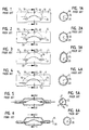
- Figure 1 is an elevation and cross-sectional view of a prior art arc tube illustrating a cylindrical chamber with lowered electrodes.
- Figure 2 is an elevation and cross-sectional view of a prior art arc tube illustrating an asymmetrically pinched cylindrical chamber with lowered electrodes.
- Figure 3 is an elevation and cross-sectional view of a prior art arc tube illustrating a non-cylindrical, arc conforming arc tube with lowered electrodes.
- Figure 4 is an elevation and cross-sectional view of a prior art arc tube illustrating an asymmetrically pinched cylindrical chamber with lowered electrodes.
- Figure 5 is an elevation and cross-sectional view of a prior art arc tube illustrating a cylindrical chamber with a flattened bottom wall
- Figure 6 is an elevation and cross-sectional view of a prior art arc tube illustrating a cylindrical chamber with lowered electrodes.
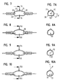
- Figure 7 is an elevation and cross-sectional view of one embodiment of the arc tube of the present invention with a cylindrical top and a planar flattened bottom.
- Figure 8 is an elevation and cross-sectional view of another embodiment of the arc tube of the present invention with a cylindrical top and a planar flattened bottom and lowered electrodes.
- Figure 9 is an elevation and cross-sectional view of another embodiment of the arc tube of the present invention with a cylindrical top and V-shaped flattened bottom.
- Figure 10 is an elevation and cross-sectional view of another embodiment of the arc tube of he present invention with a cylindrical top and large radius bottom and lowered electrodes.
- Figure 11 is a schematic representation of the cross-section of a portion of an embodiment of the arc tube of the present invention illustrating the planar relationship of the bottom of the circles which define the top of the arc tube.
- Figure 12 is a schematic representation of the cross-section of a portion of an embodiment of an arc tube of the present invention illustrating a non-planar relationship of the bottom of the circles which define the top of the arc tube.
- Figure 13 is an elevation and cross-sectional view of an embodiment of an arc tube of the present invention illustrating the relationship of the diameter of the circle through the center of the arc tube to the length thereof and the arcuate portion of the circle which has been generally flattened.
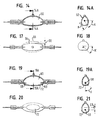
- Figure 14 is an elevation and cross-sectional view of another embodiment of the arc tube of the present invention illustrating the narrowed sides with respect to axial electrodes and the arc subtended by the flattened portion.
- Figure 15 is a top plan view of the arc tube of Figure 14.
- Figure 16 is a bottom view of the arc tube of Figure 14 illustrating the shape of the flattened portion.
- Figure 17 is a top plan view of the arc tube of Figure 14 illustrating the degree of narrowing at the elevation of the electrodes.
- Figure 18 is cross-sectional view of an arc tube illustrating one design in the narrowing thereof.
- Figure 19 is an elevation and cross-sectional view of another embodiment of the arc tube of the present invention illustrating the tilting of the electrodes in a narrow arc tube and the angle at the electrodes subtended by the flattened portion.
- Figure 20 is a bottom view of another embodiment of the arc tube of the present invention with tilted electrodes and a shallow v-shaped flattened portion.
- Figure 21 is a cross-sectional view of the arc tube of Figure 20 illustrating the arcuate portions thereof.
- Figure 22 is a pictorial representation of one embodiment of the horizontal burning HID lamp of the present invention.
- Figures 23 - 26 are pictorial views illustrating the process of using a lathe and torch to make the arc tube of the present invention from a tube of vitreous material
- the arc tube of the present invention includes a light emitting chamber formed in any suitable conventional manner with a pair of spaced apart, coaxial electrodes extending through the closed ends thereof.
- the arc tube may be formed of quartz or a slip cast ceramic.
- the upper portion 31 of the arc tube in cross-section is preferentially the arc of a circle, i.e. a constant distance from the axis 30 of the electrodes 32.
- the cylindrical upper portion 31 of the arc tube continues downwardly for an angle ⁇ of between about 20 degrees and about 80 degrees below the horizontal on both sides, preferably between about 30 degrees and 60 degrees, where the arc joins the flattened bottom portion 33.
- the loci 36 of the points of junction of the top portion and bottom portion form lines inclined to each other and to the axis 30 of the electrodes 32.
- the cross-section of the chamber 34 is generally the same between the electrodes, i.e. the bottom is substantially planar between the electrodes, and the center of the circles which define the upper portion of the arc tube are coaxial with the electrodes.
- the radius of the circles gradually decrease from the radius Rc at the center section of Figure 7A through radii R1, R2, etc. to both ends of the chamber 34. This results in a continuing decrease in the cross-sectional area from the center of the chamber to the ends thereof as well as a slight decrease in the horizontal width of the flat bottom from the center of the chamber toward the ends thereof.
- the radii of the circles defining the cross-section of the chamber 34 may decrease as shown in Figure 11 but the centers may be lowered to place the lower tangent in the same horizontal plane. This increases the surface of the bottom of the chamber and steepens the decline of the top wall 31 from the center of the chamber to both ends.
- the axis 30 of the electrodes 32 may be lowered relative to the axis of the circle defining the central cross-section of the chamber while maintaining a planar bottom between the electrodes.
- the axis 30 of the electrodes may be coaxial with the axis of the circle defining the central cross-section and the bottom independently shaped to form a bottom 33 which is slightly v-shaped across the width of the chamber.
- the axis 30 of the electrodes may be lowered with respect to the axis of the circle defining the central cross-section and bottom independently shaped to produce a bottom 33 which has a radius of curvature R which is large with respect to the radius Rc of the circle through the center of the upper portion of the chamber, preferably a ratio R/Rc between about 1.5 and about 5.0.
- R radius of curvature
- a slight v-shape or large radius curve may also be provided along the bottom portion of the chamber from end to end.
- the object in all embodiments is to provide an essentially flat bottom to the chamber to thereby increase the surface area of the halide pool and thus the vapor pressure of the halides in the arc.
- This bottom may be curved or v-shaped both longitudinally and/or transversely of the arc tube.
- Formed body arc tubes provide great manufacturing flexibility and may,, e.g., be manufactured in the manner described in the Sulcs et al copending patent application Serial No. filed and entitled "Method of Making Optical Coupling Device" (Case 2159) assigned to the assignee of the present invention, the disclosure of which is hereby incorporated herein by reference.
- a tube 80 of quartz or other vitreous material is shown held by an axially stationary holding device or headstock 82 and an axially moveable holding device or tailstock 84.
- the tube 80 may be heated in a conventional manner by one or more torches 86 near the stocks 82 and 84 to compensate for any longitudinal curvature in the tube 80 and to relieve the stress of griping by the tailstock 84.
- the central section of the tube 80 may be heated by a torch 86 to soften the tube in the area where the chamber is to be formed. Movement of the tailstock 84 toward the headstock 82 will cause the softened tube to compress and the lateral displacement of the material forms a thicken wall area 88. As shown in Fig 25, the steps of localized heating and axial movement of the tailstock are repeated until the wall of the tube 80 has been thickened over the entire area which is to become the arc tube chamber. Note that the thickening is carefully controlled relative to the diameter of the tube 80 so that a passageway remains through the tube 80 after the gathering process is completed.
- the entire gathered area 90 may then be heated with a torch 86 to soften the material into a malleable state in which it can be molded.
- the two sides 92,94 of a mold may then be placed over the softened and thickened area 90 of the tube, one end of the tube sealed in a conventional manner by a plug 96, and a gas introduced into the other end of the tube from a suitable conventional source (not shown).
- the pressure of the gas internally of the thickened tube expands the outer walls against the mold, thinning the outer walls in the process, desirably to the approximate thickness of the tube as originally placed in the lathe. This results is the formation of an arc tube chamber having the shape of the mold.
- the thickness of the wall may be controlled in the gathering process, i . e ., it may be desirable to have the wall thicker or thinner than the wall thickness of the original tube.
- the thickness may also be influenced by the orientation of the mold because the softened glass tends to flow under the influence of gravity once the rotation of the tube is stopped for the placement of the mold thereover.
- the heat absorption of the glass is a function of its thickness and it has been found desirable to split the mold horizontally rather than vertically. It has also been found that the softened glass tends to flow downwardly under the influence of gravity when rotation of the tube is stopped to position the mold with respect thereto.
- the wall thickness may be slightly thicker on the lower side of the mold and it has been found desirable to position the mold bottom side uppermost in forming the arc tube.
- the arc tube may be made in symmetrical or asymmetrical shapes which are difficult to produce by pinch sealing of a cylindrical tube.
- the bottom of the arc tube is between about 20 and about 80 percent of the length and width of the chamber, preferably between about 50 and about 60 percent of the length.
- the tube is between about 5 mm and 7 mm in diameter and the maximum height of the mold cavity is between about 10 mm and about 30 mm.
- This process of arc tube formation facilitates the formation of an arc tube chamber in which the electrodes may be lowered within the chamber to accommodate for the bow in the arc.
- the distance from the bowed arc to the chamber wall is decreased, particularly in the area of the electrodes where the cold spots customarily form.
- the temperature of the chamber wall is made more uniform.
- the flattening of the bottom portion of the chamber increases the surface area of the halide pool for a given amount of halide, increases the exposure of the pool to the arc, and thus increases the vapor pressure of the halides in the chamber. The color quality and light output are thus improved.
- tests have indicated a twenty to thirty percent increase in the efficacy or lumens per watt of lamps employing the arc tube of the present invention with little sensitivity to slight tilting of the lamp from the horizontal.
- the ratio of the length L to the nominal height 2Rc, or aspect ratio, of the arc tube is between about 4 and about 1, preferably between about 3.0 and 1.5 with the angle ⁇ between the junction of the flattened bottom and the sides of the arc tube below the horizontal being between about 20 and about 80 degrees, preferably between about 30 and about 60 degrees.
- the chamber 60 may be narrowed as best seen in Figure 14A. bringing the side walls closer to the arc than would result from the formation of the arc tube from a tube cylindrical in cross-section. This narrowing may result in a ovate flat bottom as shown in Figure 16 as the flat portion of the bottom also narrows from the center towards both ends of the arc tube.
- This narrowing may be achieved by effectively removing the center section D of the arc tube of Figure 10A as is shown in Figure 18. This retains the arcuate shape of the walls 62 of the arc tube, i.e., the circle radius R is maintained but the center of such arcs are displaced horizontally from the longitudinal center of the chamber.
- the side walls 64 are moved inwardly with respect to the position 66 thereof as shown in the arc tube of Figure 7 a distance D2 which effects a reduction of the maximum width of the Figure 7 embodiment at the longitudinal center thereof between about 5 percent and about 50 percent, preferably between about 10 and about 40 percent.
- canoe-shaped includes flattened bottoms which are planar, and those which are either a shallow v-shape or arcuate from end-to-end and/or side-to-side.
- FIG. 19 A further embodiment is illustrated in Figure 19 where the electrodes 68 are tilted downwardly toward the free ends thereof at an angle to the horizontal between about 5 and about 40 degrees, preferably between about 10 and about 20 degrees. This has the effect of further lowering the arc within the chamber 60 and makes the angle ⁇ at the free end of the electrodes 68 from the vertical to the junction 70 of the arcuate side walls and the flattened bottom between about 80 degrees and about 20 degrees, preferably between about 60 and about 30 degrees.
- the term "tilted” includes both the angular attachment of a wire electrode and the axial attachment of an electrode which has been bent to the desired angle. Because the electrodes are typically made of tungsten and may be brittle, the electrodes may have to be heated prior to the bending
- the distance D3 which the free ends of the electrodes 68 are lowered places the free ends of the electrodes between about 10 and about 50 percent, preferably between about 25 and about 33 percent, of the height of the chamber at the free ends of the electrodes.
- the flattened bottom 72 of the arc tube may be arcuate as shown in Figure 19 or slightly v-shaped as shown in the bottom view of Figure 20 and the cross-sectional view of Figure 21.
- the flattened bottom is desirably concave upwardly from end-to-end and from side-to-side which tends to keep the pool in the center of the chamber and thus reduces the susceptibility of the arc tube to minor changes in position relative to the horizontal.
- halides are substantially transparent to infra red radiation and absorbent of ultra violet radiation from the arc.
- the increased surface area of the halide pool increases the area of absorption and may increase the temperature of the condensate and thus the amount of halide in the arc.
- lamps 50 may include a conventional mogel base 52 and an outer envelope 54 in which a flat bottomed arc tube 56 may be mounted in any suitable conventional manner. Because the are tube is rotationally fixed relative to the lamp base, and because the arc tube is operational only with the flat side down, it is desirable that the base be configured in any suitable conventional way to mate with the lamp fixture only in a predetermined manner which achieves that result.
Landscapes
- Chemical & Material Sciences (AREA)
- Engineering & Computer Science (AREA)
- Materials Engineering (AREA)
- Organic Chemistry (AREA)
- Manufacturing & Machinery (AREA)
- Vessels And Coating Films For Discharge Lamps (AREA)
Applications Claiming Priority (2)
| Application Number | Priority Date | Filing Date | Title |
|---|---|---|---|
| US09/597,549 US6857926B1 (en) | 2000-06-19 | 2000-06-19 | Method of making arc tubes |
| US597549 | 2000-06-19 |
Publications (1)
| Publication Number | Publication Date |
|---|---|
| EP1189254A2 true EP1189254A2 (fr) | 2002-03-20 |
Family
ID=24391992
Family Applications (1)
| Application Number | Title | Priority Date | Filing Date |
|---|---|---|---|
| EP01114654A Withdrawn EP1189254A2 (fr) | 2000-06-19 | 2001-06-19 | Procédé pour la fabrication de tubes à arc |
Country Status (2)
| Country | Link |
|---|---|
| US (1) | US6857926B1 (fr) |
| EP (1) | EP1189254A2 (fr) |
Cited By (3)
| Publication number | Priority date | Publication date | Assignee | Title |
|---|---|---|---|---|
| CN101088136B (zh) * | 2004-10-26 | 2010-05-26 | 通用电气公司 | 整体成形的模制品及其制造方法 |
| EP2702605A2 (fr) * | 2011-04-27 | 2014-03-05 | Koninklijke Philips N.V. | Lampe à décharge à température de couleur élevée |
| CN108314298A (zh) * | 2018-02-28 | 2018-07-24 | 东南大学 | 用于电弧管泡壳成形的夹头装置及电弧管泡壳成形方法 |
Families Citing this family (9)
| Publication number | Priority date | Publication date | Assignee | Title |
|---|---|---|---|---|
| DE10204925A1 (de) * | 2002-02-07 | 2003-08-21 | Philips Intellectual Property | Quecksilberfreie Hochdruckgasentladungslampe |
| GB2397067B (en) * | 2002-12-23 | 2005-05-11 | Destiny Pharma Ltd | Porphin & azaporphin derivatives with at least one cationic-nitrogen-containing meso-substituent for use in photodynamic therapy & in vitro sterilisation |
| DE102004005903A1 (de) * | 2004-02-05 | 2005-08-25 | Patent-Treuhand-Gesellschaft für elektrische Glühlampen mbH | Hochdruckentladungslampe und Herstellungsverfahren für eine Hochdruckentladungslampe |
| US7595583B2 (en) * | 2004-02-25 | 2009-09-29 | Panasonic Corporation | Cold-cathode fluorescent lamp and backlight unit |
| GB2415372A (en) | 2004-06-23 | 2005-12-28 | Destiny Pharma Ltd | Non photodynamical or sonodynamical antimicrobial use of porphyrins and azaporphyrins containing at least one cationic-nitrogen-containing substituent |
| CN102496557B (zh) * | 2011-11-24 | 2015-02-11 | 上海亚明灯泡厂有限公司 | 陶瓷放电容器及金属卤化物灯 |
| US9552976B2 (en) | 2013-05-10 | 2017-01-24 | General Electric Company | Optimized HID arc tube geometry |
| EP3088370B1 (fr) * | 2015-04-28 | 2018-09-26 | Heraeus Quarzglas GmbH & Co. KG | Procédé et dispositif de fabrication d'un tube en verre |
| JP6660594B2 (ja) * | 2016-04-28 | 2020-03-11 | ウシオ電機株式会社 | 放電ランプ |
Family Cites Families (14)
| Publication number | Priority date | Publication date | Assignee | Title |
|---|---|---|---|---|
| US3504819A (en) | 1966-02-21 | 1970-04-07 | Owens Illinois Inc | Lamp envelopes |
| GB1401293A (en) | 1972-04-19 | 1975-07-16 | Gen Electric Co Ltd | Electric discharge lamps |
| US3858078A (en) | 1973-07-09 | 1974-12-31 | Gte Sylvania Inc | Metal halide discharge lamp having an arched arc tube |
| NL7503164A (nl) | 1974-03-20 | 1975-09-23 | Thorn Electrical Ind Ltd | Boogontladingsbuis voor hogedruk kwik/metaal- halogenide lampen. |
| US4056751A (en) | 1976-03-22 | 1977-11-01 | Gte Sylvania Incorporated | Metal halide discharge lamp having optimum electrode location |
| NL7711134A (nl) | 1976-10-19 | 1978-04-21 | Gen Electric Co Ltd | Elektrische hoge druk ontladingslamp. |
| US4498027A (en) | 1982-06-11 | 1985-02-05 | Gte Products Corporation | Arc discharge lamp with improved starting capabilities, improved efficacy and maintenance, and line-of-sight arched arc tube for use therewith |
| US4891555A (en) * | 1985-11-15 | 1990-01-02 | General Electric Company | Metal vapor discharge lamps |
| US4850499A (en) | 1986-12-18 | 1989-07-25 | Gte Products Corporation | Method to reduce color temperature variation in metal halide arc tubes |
| US5055740A (en) | 1987-02-25 | 1991-10-08 | Venture Lighting Interntional, Inc. | Horizontal burning metal halide lamp |
| DE3910878A1 (de) * | 1989-04-04 | 1990-10-11 | Patent Treuhand Ges Fuer Elektrische Gluehlampen Mbh | Zweiseitig gesockelte hochdruckentladungslampe |
| US5016150A (en) | 1989-10-19 | 1991-05-14 | Musco Corporation | Means and method for increasing output, efficiency, and flexibility of use of an arc lamp |
| EP0581359B1 (fr) | 1992-07-20 | 1999-02-24 | Koninklijke Philips Electronics N.V. | Lampe de décharge à haute intensité avec un tube avec des pincements décentrés |
| US5539271A (en) | 1994-12-12 | 1996-07-23 | Venture Lighting International, Inc. | Horizontal burning metal halide lamp |
-
2000
- 2000-06-19 US US09/597,549 patent/US6857926B1/en not_active Expired - Fee Related
-
2001
- 2001-06-19 EP EP01114654A patent/EP1189254A2/fr not_active Withdrawn
Cited By (3)
| Publication number | Priority date | Publication date | Assignee | Title |
|---|---|---|---|---|
| CN101088136B (zh) * | 2004-10-26 | 2010-05-26 | 通用电气公司 | 整体成形的模制品及其制造方法 |
| EP2702605A2 (fr) * | 2011-04-27 | 2014-03-05 | Koninklijke Philips N.V. | Lampe à décharge à température de couleur élevée |
| CN108314298A (zh) * | 2018-02-28 | 2018-07-24 | 东南大学 | 用于电弧管泡壳成形的夹头装置及电弧管泡壳成形方法 |
Also Published As
| Publication number | Publication date |
|---|---|
| US6857926B1 (en) | 2005-02-22 |
Similar Documents
| Publication | Publication Date | Title |
|---|---|---|
| US6857926B1 (en) | Method of making arc tubes | |
| US5138227A (en) | High-pressure discharge lamp, particularly double-ended high-power, high-wall loading discharge lamp, and method of making the same | |
| CN101494152A (zh) | 荧光灯 | |
| EP1174904A1 (fr) | Procédé d'amélioration des caractéristiques des lampes à décharge de grande puissance fonctionnant en position horizontale | |
| US5055740A (en) | Horizontal burning metal halide lamp | |
| US6781312B1 (en) | Horizontal burning hid lamps and arc tubes | |
| US5986403A (en) | Method for making a capped electric lamp by using reduced internal pressure to collapse glass | |
| JPH06162996A (ja) | 高圧放電ランプ | |
| US5913705A (en) | Method of making a halogen incandescent lamp | |
| CA2396801C (fr) | Tube a arc a quartz pour lampe aux halogenures et methode de fabrication | |
| CA1293291C (fr) | Methode pour reduire les variations de la temperature de couleur dans les lampes a halogenure de metal | |
| JP3958369B2 (ja) | 高圧放電ランプ | |
| US5734227A (en) | Incandescent lamps and process for producing the same | |
| JPH0115974B2 (fr) | ||
| EP1063672B1 (fr) | Procédé de fabrication d'une lampe | |
| US5006088A (en) | Method of making a pinch-sealed, gas-filled incandescent lamp | |
| US4850500A (en) | Dimpled arc tube having no internal end pockets and a lamp employing same | |
| JP2629933B2 (ja) | ガラス管球 | |
| US20070001576A1 (en) | Double-sided sealed electric lamp and method for production thereof | |
| US3511405A (en) | Lamp envelope with integral cooling chamber and method of making same | |
| EP1564785A1 (fr) | Lampe à décharge et son procédé de fabrication | |
| JPH0389448A (ja) | 管形電球 | |
| JP2002042656A (ja) | 管球の封止方法および管球 | |
| GB2092823A (en) | Fluorescent Lamp | |
| KR20050060990A (ko) | 유도결합형 무전극 환형 형광램프용 벌브 및 그의 제조방법 |
Legal Events
| Date | Code | Title | Description |
|---|---|---|---|
| PUAI | Public reference made under article 153(3) epc to a published international application that has entered the european phase |
Free format text: ORIGINAL CODE: 0009012 |
|
| AK | Designated contracting states |
Kind code of ref document: A2 Designated state(s): AT BE CH CY DE DK ES FI FR GB GR IE IT LI LU MC NL PT SE TR |
|
| AX | Request for extension of the european patent |
Free format text: AL;LT;LV;MK;RO;SI |
|
| 18W | Application withdrawn |
Effective date: 20030731 |
|
| STAA | Information on the status of an ep patent application or granted ep patent |
Free format text: STATUS: THE APPLICATION HAS BEEN WITHDRAWN |
|
| R18W | Application withdrawn (corrected) |
Effective date: 20030731 |