EP1189310A2 - Steckverbinderstruktur und weiblicher Verbinder - Google Patents
Steckverbinderstruktur und weiblicher Verbinder Download PDFInfo
- Publication number
- EP1189310A2 EP1189310A2 EP01121661A EP01121661A EP1189310A2 EP 1189310 A2 EP1189310 A2 EP 1189310A2 EP 01121661 A EP01121661 A EP 01121661A EP 01121661 A EP01121661 A EP 01121661A EP 1189310 A2 EP1189310 A2 EP 1189310A2
- Authority
- EP
- European Patent Office
- Prior art keywords
- female
- connector
- male
- contacts
- female connector
- Prior art date
- Legal status (The legal status is an assumption and is not a legal conclusion. Google has not performed a legal analysis and makes no representation as to the accuracy of the status listed.)
- Withdrawn
Links
- 239000000758 substrate Substances 0.000 claims abstract description 52
- 238000009434 installation Methods 0.000 claims description 15
- 238000000034 method Methods 0.000 abstract description 6
- 238000003780 insertion Methods 0.000 description 4
- 230000037431 insertion Effects 0.000 description 4
- 239000007769 metal material Substances 0.000 description 2
- 230000002093 peripheral effect Effects 0.000 description 2
- 238000005452 bending Methods 0.000 description 1
- 239000000470 constituent Substances 0.000 description 1
- 230000000694 effects Effects 0.000 description 1
- 238000004519 manufacturing process Methods 0.000 description 1
- 239000000463 material Substances 0.000 description 1
- 238000005192 partition Methods 0.000 description 1
- 230000002250 progressing effect Effects 0.000 description 1
- 238000000926 separation method Methods 0.000 description 1
Images




Classifications
-
- H—ELECTRICITY
- H01—ELECTRIC ELEMENTS
- H01R—ELECTRICALLY-CONDUCTIVE CONNECTIONS; STRUCTURAL ASSOCIATIONS OF A PLURALITY OF MUTUALLY-INSULATED ELECTRICAL CONNECTING ELEMENTS; COUPLING DEVICES; CURRENT COLLECTORS
- H01R12/00—Structural associations of a plurality of mutually-insulated electrical connecting elements, specially adapted for printed circuits, e.g. printed circuit boards [PCB], flat or ribbon cables, or like generally planar structures, e.g. terminal strips, terminal blocks; Coupling devices specially adapted for printed circuits, flat or ribbon cables, or like generally planar structures; Terminals specially adapted for contact with, or insertion into, printed circuits, flat or ribbon cables, or like generally planar structures
- H01R12/70—Coupling devices
- H01R12/71—Coupling devices for rigid printing circuits or like structures
-
- H—ELECTRICITY
- H01—ELECTRIC ELEMENTS
- H01R—ELECTRICALLY-CONDUCTIVE CONNECTIONS; STRUCTURAL ASSOCIATIONS OF A PLURALITY OF MUTUALLY-INSULATED ELECTRICAL CONNECTING ELEMENTS; COUPLING DEVICES; CURRENT COLLECTORS
- H01R12/00—Structural associations of a plurality of mutually-insulated electrical connecting elements, specially adapted for printed circuits, e.g. printed circuit boards [PCB], flat or ribbon cables, or like generally planar structures, e.g. terminal strips, terminal blocks; Coupling devices specially adapted for printed circuits, flat or ribbon cables, or like generally planar structures; Terminals specially adapted for contact with, or insertion into, printed circuits, flat or ribbon cables, or like generally planar structures
- H01R12/70—Coupling devices
- H01R12/7076—Coupling devices for connection between PCB and component, e.g. display
-
- H—ELECTRICITY
- H01—ELECTRIC ELEMENTS
- H01R—ELECTRICALLY-CONDUCTIVE CONNECTIONS; STRUCTURAL ASSOCIATIONS OF A PLURALITY OF MUTUALLY-INSULATED ELECTRICAL CONNECTING ELEMENTS; COUPLING DEVICES; CURRENT COLLECTORS
- H01R12/00—Structural associations of a plurality of mutually-insulated electrical connecting elements, specially adapted for printed circuits, e.g. printed circuit boards [PCB], flat or ribbon cables, or like generally planar structures, e.g. terminal strips, terminal blocks; Coupling devices specially adapted for printed circuits, flat or ribbon cables, or like generally planar structures; Terminals specially adapted for contact with, or insertion into, printed circuits, flat or ribbon cables, or like generally planar structures
- H01R12/70—Coupling devices
- H01R12/71—Coupling devices for rigid printing circuits or like structures
- H01R12/712—Coupling devices for rigid printing circuits or like structures co-operating with the surface of the printed circuit or with a coupling device exclusively provided on the surface of the printed circuit
- H01R12/716—Coupling device provided on the PCB
-
- H—ELECTRICITY
- H01—ELECTRIC ELEMENTS
- H01R—ELECTRICALLY-CONDUCTIVE CONNECTIONS; STRUCTURAL ASSOCIATIONS OF A PLURALITY OF MUTUALLY-INSULATED ELECTRICAL CONNECTING ELEMENTS; COUPLING DEVICES; CURRENT COLLECTORS
- H01R12/00—Structural associations of a plurality of mutually-insulated electrical connecting elements, specially adapted for printed circuits, e.g. printed circuit boards [PCB], flat or ribbon cables, or like generally planar structures, e.g. terminal strips, terminal blocks; Coupling devices specially adapted for printed circuits, flat or ribbon cables, or like generally planar structures; Terminals specially adapted for contact with, or insertion into, printed circuits, flat or ribbon cables, or like generally planar structures
- H01R12/50—Fixed connections
- H01R12/51—Fixed connections for rigid printed circuits or like structures
- H01R12/55—Fixed connections for rigid printed circuits or like structures characterised by the terminals
- H01R12/57—Fixed connections for rigid printed circuits or like structures characterised by the terminals surface mounting terminals
-
- H—ELECTRICITY
- H01—ELECTRIC ELEMENTS
- H01R—ELECTRICALLY-CONDUCTIVE CONNECTIONS; STRUCTURAL ASSOCIATIONS OF A PLURALITY OF MUTUALLY-INSULATED ELECTRICAL CONNECTING ELEMENTS; COUPLING DEVICES; CURRENT COLLECTORS
- H01R2201/00—Connectors or connections adapted for particular applications
- H01R2201/06—Connectors or connections adapted for particular applications for computer periphery
Definitions
- the present invention relates to a connector structure, a female connector, and a male connector for internal mounting for implementing the connection between, for example, a substrate and a peripheral device that is directly disposed on this substrate.
- PC personal computers
- miniaturization is rapidly progressing, and PCs have appeared that use a structure in which peripheral devices are mounted on the substrate called the motherboard provided internally.
- the motherboard provided internally.
- the hard disc drive that serves as the main memory device is mounted on the substrate.
- the hard disc drive d is placed on the substrate b such that the female connector 1 on the substrate b is opposite to the male connector 2 of the hard disc drive d, and then the hard disc drive d is slid on the substrate b, and the male contacts 3 of the male connector 2 are connected by insertion into the female contacts 4 of the female connector 1.
- This type of method of engagement originates in the shape of the male and female connectors since the female connector 1 can receive the insertion of the male connector 2 only in a direction parallel to the substrate b.
- a connector structure according to the claim 1 comprises a female connector and a male connector being connectable to the female connector, wherein the female connector comprises female contacts and a mounting surface, which is mountabe on an installation surface, wherein the female contacts are provided inside grooves, and wherein the grooves are formed in a direction with a component which is perpendicular to said mounting surface of said female connector.
- said female connector is fixed either to the installation surface or the object to be installed on said installation surface, and said male connector is fixed on the other.
- said installation surface is one of the surfaces of the substrate, and said object is a device mounted on said substrate.
- said female connector is fixed by bringing said bottom into contact with said installation surface, wherein said male connector is fixed by said male contacts protruding sideways from said object, wherein said female contact is provided in groups of two by separating them in a said substantially perpendicular direction in said groove, and wherein one of said female contacts is disposed so as to be in closer proximity to said bottom than the other female contact and in proximity to said side surface, wherein said male contact is provided in groups of two corresponding to said female contacts; and the other male contact corresponding to said other female contact is shorter than the other male contact corresponding to said other female contact, and is disposed by being placed in proximity to the bottom of said object.
- said female contact comprises a pair of elastically deformable catches, and said male contacts are sandwiched between said catches.
- said female contact comprises an elastically deformable catch and a wall separated from and opposed to said catch, and said male contact is sandwiched between said catch and said wall.
- said grooves are provided in plurality on said female connector, and said male connectors correspond to the plurality of said grooves, and a plurality of male contacts are provided.
- either a projection or recess that can be partnered is provided in said female connector, wherein either of the other of said projection or recess is provided on said male connector so as to fit a partner when connected to said female connector; and said projection and recess are provided shifted away from the center in the widthwise direction on both said female connector and said male connector.
- the grooves are substantially perpendicular to said mounting surface of said female connector.
- An inventive female connector comprises female contacts and a mounting surface, which is mountable on an installation surface, wherein the female contacts are provided inside grooves, and wherein the grooves are formed in a direction with a component which is perpendicular to said mounting surface of said female connector.
- said female connectors are provided in groups of two separated in said grooves in said substantially perpendicular direction inside said grooves, and one of the female contacts is disposed more in proximity to said bottom than the other female contact, and in proximity to said side surface.
- said mounting surface is an opposite surface of the upper surface.
- said mounting surface is substantially in parallel with said upper surface.
- said mounting surface and said front surface are neigbouring surfaces.
- said mounting surface has a perpendicular component with respect to said front surface.
- a further inventive female connector and a further inventive connector structure comprise female ontacts, an upper surface and a front surface, wherein said female contacts are provided inside grooves, and wherein a groove has a portion in the upper surface and a portion in the front surface.
- said female connector further comprises a mounting surface.
- said mounting surface is mountable on an installation surface.
- An inventive male connector is characterized in that the male contacts are provided in groups of two, and one male contact is formed so as to be shorter than the other male contact.
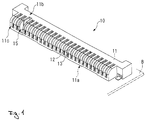
- Fig. 1 is a perspective drawing showing the female connector of the first embodiment of the present invention.
- Fig. 2 is a perspective drawing showing the male connector of the first embodiment of the present invention.
- Fig. 3 is a perspective drawing showing the state in which the female connector and the male connector are connected.
- Fig. 4 is a perspective drawing showing the state in which the female connector and the male connector are opposite each other on the substrate.
- Fig. 5 is a perspective drawing showing the state in which the female connector a male connector are connected and the hard disc drive is mounted on the substrate.
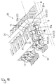
- Fig. 6 is a planar drawing showing the female connector of the second embodiment of the present invention.
- Fig. 7 is an explanatory drawing showing the process in which the hard disc drive is mounted on the substrate using the conventional connector structure.
- the first embodiment of the connector structure according to the present invention will be explained referring to Fig. 1 through Fig. 5. Moreover, in the present embodiment, an example of a connector structure used when mounting a hard disc drive that is the object on the installation surface of a substrate will be explained.
- Fig. 1 shows the female connector
- Fig. 2 shows the male connector
- Fig. 3 shows the state in which the female connector 10 and the male connector 20 are connected
- Fig. 4 shows the state in which the female connector 10 on substrate B and the male connector 20 are opposite each other
- Fig. 5 shows the state in which the female connector 10 and the male connector 20 are connected and the hard disc drive is mounted on the substrate B.
- the base 11 forming the female connector 10 has a shape that is long in the lateral direction, and the lower surface 11a is anchored so as to lie on the substrate B.
- grooves 12 formed in a direction perpendicular to the lower surface 11a and opening continuously on the upper surface 11b and side surface (or front surface) 11c thereof are provided in plurality in parallel in the width direction of the base 11.
- female contacts 13 are each disposed inside all of the grooves 12 (refer to Fig. 1).
- Female contacts 13 are provided in groups of two inside each of the grooves 12.
- the female contacts 13a and 13b that serve as one group are separated in the direction of disposition of the grooves 12, that is, in the direction perpendicular to the substrate.
- One of the female contacts 13a is more in proximity to the lower surface 11a than the other female contact 13b, and is disposed in proximity to the side surface 11c in which the grooves 12 open (refer to Fig. 4).
- a base 21 that forms the male connector 20 has a shape that is long in the lateral direction like the female connector 10.
- holes passing from one surface to the other surface are provided parallel to the base 21 in the widthwise direction and on two vertical levels.
- male contacts 22 are each inserted and disposed, with the distal end protruding from one side surface 21a and the base projecting from the other side surface.
- the distal end of a male contact 22 protrudes from the side surface towards the hard disc drive D, and is anchored (refer to Fig. 2).
- the male contacts 22 form groups of two separated vertically.
- the projection length of the one male contact 22a on the lower level that is in proximity to the lower surface of the hard disc drive D and corresponds to the female contact 13a is formed shorter from the side surface 21a than the other male contact 22b corresponding to the female contact 13b (refer to Fig. 5).
- the female contact 13 is formed by stamping and bending processing a metal material having superior conductivity into a predetermined shape, and has a pair of catches 14a and 14b that are elastically deformable.
- the distal ends of the catches 14a and 14b have an arc-shaped cross-section, and are disposed so that the projecting surfaces oppose each other.
- the separation between the catches 14a and 14b is set so as to be narrower than the thickness of the distal end of the male contact 22, and the female contact and male contacts are engaged so as to allow electrical conduction by the distal end of the male contact 22 being inserted so as to be sandwiched between the catches 14a and 14b.
- the catches 14a and 14b are disposed separated in the widthwise direction of the base 11 so that the gap between the catches 14a and 14b in the grooves 12 passes through from the direction of disposition of the grooves 12, that is, in the direction perpendicular to the base. This is in order to allow the insertion of a male contact 22 in between the catches 14a and 14b.
- a recess 15 is provided so as to partition the grooves 12.
- This recess 15 opens continuously on the upper surface 11b of the base 11 to the side surface 11c like the grooves 12. Moreover, the recess 15 is formed at a position shifted away from the center of the base 11 in the widthwise direction.
- a projection 23 is provided that fits into the recess 15 when connected with the female connector 10.
- This recess 23 is also formed at a position shifted away from the center of the base 21 in the widthwise direction.
- a slanted surface 23a is formed so that the projection 23 can be easily guided into the recess 15.
- the hard disc drive D is disposed on the upper side of the substrate B (refer to Fig. 4). At this time, care is taken so that each of the male contact 22a and 22b groups are disposed directly above each of the grooves 12, and the projection 23 is positioned directly above the recess 15.
- the hard disc drive D is slowly moved towards the substrate B, and the projection 23 is inserted into the recess 15 from the lower part. Subsequently, the hard disc drive D continues to be moved towards the substrate B, and the male contacts 22a of the lower level and the male contacts 22b of the upper level are inserted in sequence into the grooves 12 (refer to Fig. 5). Moreover, this operation should progress simultaneously and continuously for the male contacts 22a and 22b corresponding respectively to all of the grooves 12.
- the distal ends of the male contacts 22a and 22b inserted into the grooves 12 substantially simultaneously abut the distal ends of the catches 14a and 14b of each of the corresponding female contacts 13a and 13b.
- the gap between the catches 14a and 14b is set so as to be narrower than the thickness of the male contacts 22a and 22b, the insertion of the male contacts 22a and 22b between the catches 14a and 14b cannot be carried out easily, and thus in the operation of moving the hard disc drive D closer to the substrate B, a resistance force occurs as long as a space exists between the substrate B and the hard disc drive D.
- the male contacts 22a and 22b push open the catches 14a and 14b, and enter therebetween.
- the female contacts 13a and 13b and the male contacts 22a and 22b are electrically engaged.
- the bottom surface of the hard disc drive D abuts the substrate B, and a stable positioning is guaranteed.
- the action of sliding the hard disc drive D on the substrate B does not occur, and thus providing an open space for moving the hard disc drive D on the substrate B is not necessary, and the size of the substrate B can be reduced by a corresponding amount.
- the PC itself having the substrate mounted can be miniaturized.
- both of the connectors 10 and 20 can be connected without a polarity error. Moreover, providing a projection on the female connector 10 and a recess on the male connector 20 attain the same effects, and are not limited by the present embodiment.
- the structures of the connectors of the present embodiment are not limited to a substrate and a hard disc drive, but of course by providing these respectively on two objects that are to be electrically connected, the connection can be realized.
- the connector structure of the present invention can also be used as a unit.
- a female connector 13a (13b) is formed from an elastically deformable catch 16 formed by a metal material having superior conductivity and a wall 17 separated from and opposite to the catch 16.
- the wall 17 is one of the walls that form a groove 12.
- the gap between a catch 16 and a wall 17 is set so as to be narrower than the thickness of the distal end of a male contact 22a (22b), and the distal end of a male contact 22a is inserted so as to be sandwiched between the catch 16 and the wall 17, and thereby the female and male contacts are electrically engaged.
- the shape of the female contact 13 is simple in comparison to that of the first embodiment described above, and can be completed using a small amount of material. Thus there is the advantage that the costs related to fabrication can be reduced.
- the male contacts are brought into contact with the female connector from a substantially perpendicular direction, and in this process, by the male contacts being inserted into the grooves and engaging the female contacts, a state of contact between both contacts is attained.
- the substrate can be reduced by an amount corresponding to the open space, and the apparatus itself built into this substrate can be miniaturized.
Landscapes
- Coupling Device And Connection With Printed Circuit (AREA)
- Details Of Connecting Devices For Male And Female Coupling (AREA)
Applications Claiming Priority (2)
| Application Number | Priority Date | Filing Date | Title |
|---|---|---|---|
| JP2000278632A JP2002093501A (ja) | 2000-09-13 | 2000-09-13 | コネクタ構造、雌コネクタおよび雄コネクタ |
| JP2000278632 | 2000-09-13 |
Publications (2)
| Publication Number | Publication Date |
|---|---|
| EP1189310A2 true EP1189310A2 (de) | 2002-03-20 |
| EP1189310A3 EP1189310A3 (de) | 2002-08-07 |
Family
ID=18763765
Family Applications (1)
| Application Number | Title | Priority Date | Filing Date |
|---|---|---|---|
| EP01121661A Withdrawn EP1189310A3 (de) | 2000-09-13 | 2001-09-13 | Steckverbinderstruktur und weiblicher Verbinder |
Country Status (6)
| Country | Link |
|---|---|
| US (1) | US6644980B2 (de) |
| EP (1) | EP1189310A3 (de) |
| JP (1) | JP2002093501A (de) |
| KR (1) | KR100721894B1 (de) |
| SG (1) | SG109958A1 (de) |
| TW (1) | TW521887U (de) |
Cited By (4)
| Publication number | Priority date | Publication date | Assignee | Title |
|---|---|---|---|---|
| WO2012149233A1 (en) * | 2011-04-28 | 2012-11-01 | 3M Innovative Properties Company | An electrical connector |
| EP3675285A1 (de) * | 2018-12-25 | 2020-07-01 | Foxconn Interconnect Technology Limited | Elektrosteckverbinderanordnung |
| EP4191800A4 (de) * | 2020-07-30 | 2024-09-25 | Yokowo Co., Ltd. | Buchse und verbinder |
| TWI915389B (zh) | 2020-07-30 | 2026-02-21 | 日商友華股份有限公司 | 插座及連接器 |
Families Citing this family (17)
| Publication number | Priority date | Publication date | Assignee | Title |
|---|---|---|---|---|
| US7314377B2 (en) * | 1998-04-17 | 2008-01-01 | Fci Americas Technology, Inc. | Electrical power connector |
| TWD112938S1 (zh) * | 2005-05-09 | 2006-09-11 | 星電股份有限公司 | 連接器 |
| USD537415S1 (en) * | 2005-05-09 | 2007-02-27 | Hosiden Corporation | Connector |
| US7303401B2 (en) * | 2005-06-23 | 2007-12-04 | Fci Americas Technology, Inc. | Electrical connector system with header connector capable of direct and indirect mounting |
| JP4819618B2 (ja) | 2006-08-16 | 2011-11-24 | 富士通株式会社 | 電子機器 |
| JP5248398B2 (ja) * | 2009-04-07 | 2013-07-31 | 富士通コンポーネント株式会社 | コネクタ |
| US20100259852A1 (en) * | 2009-04-14 | 2010-10-14 | Purpose SAE Magnetics (HK) Ltd. | Hard disc drive assembly with PCB with IO and read/write connectors on the same end |
| US8264192B2 (en) | 2009-08-10 | 2012-09-11 | Emerson Climate Technologies, Inc. | Controller and method for transitioning between control angles |
| US8508166B2 (en) | 2009-08-10 | 2013-08-13 | Emerson Climate Technologies, Inc. | Power factor correction with variable bus voltage |
| US20110130043A1 (en) * | 2009-11-27 | 2011-06-02 | Wan-Tien Chen | Combination of socket and plug for battery connector |
| US9634593B2 (en) | 2012-04-26 | 2017-04-25 | Emerson Climate Technologies, Inc. | System and method for permanent magnet motor control |
| WO2014026124A1 (en) * | 2012-08-10 | 2014-02-13 | Emerson Climate Technologies, Inc. | Motor drive control using pulse-width modulation pulse skipping |
| US9077121B2 (en) * | 2012-10-22 | 2015-07-07 | Apple Inc. | Pins for connector alignment |
| DE102013107807B3 (de) * | 2013-07-22 | 2015-01-08 | Phoenix Contact Gmbh & Co. Kg | Elektrische Steckverbindung |
| CN116661072A (zh) | 2017-09-24 | 2023-08-29 | 申泰公司 | 有通用定位的光收发器 |
| CN110635273A (zh) * | 2019-10-14 | 2019-12-31 | 厦门广泓工贸有限公司 | 一种便于插接的连接器 |
| CN116325370A (zh) | 2020-10-13 | 2023-06-23 | 申泰公司 | 用于高速数据传输的具有环形连接器的竖直插入互连系统 |
Family Cites Families (10)
| Publication number | Priority date | Publication date | Assignee | Title |
|---|---|---|---|---|
| US551883A (en) * | 1895-12-24 | Harrow | ||
| JPH06101358B2 (ja) * | 1988-01-22 | 1994-12-12 | アンプ インコーポレーテッド | ヒンジコネクター |
| GB2235341B (en) * | 1989-06-15 | 1994-01-26 | Amp Inc | Electrical connector system |
| US5176528A (en) * | 1992-06-11 | 1993-01-05 | Molex Incorporated | Pin and socket electrical connnector assembly |
| TW270248B (de) * | 1993-11-17 | 1996-02-11 | Whitaker Corp | |
| US5466171A (en) * | 1994-09-19 | 1995-11-14 | Molex Incorporated | Polarizing system for a blind mating electrical connector assembly |
| JP3506202B2 (ja) * | 1997-06-30 | 2004-03-15 | 住友電装株式会社 | 基板用コネクタ |
| US6287146B1 (en) * | 1999-02-04 | 2001-09-11 | Molex Incorporated | Grounded electrical connector with tail aligner |
| JP2001006771A (ja) * | 1999-06-18 | 2001-01-12 | Nec Corp | コネクタ |
| TW433673U (en) * | 1999-09-18 | 2001-05-01 | Speed Tech Corp | An improvement of flat cable connector for disk dirves |
-
2000
- 2000-09-13 JP JP2000278632A patent/JP2002093501A/ja active Pending
-
2001
- 2001-08-22 SG SG200105140A patent/SG109958A1/en unknown
- 2001-08-28 TW TW090214727U patent/TW521887U/zh not_active IP Right Cessation
- 2001-09-12 KR KR1020010056058A patent/KR100721894B1/ko not_active Expired - Lifetime
- 2001-09-13 EP EP01121661A patent/EP1189310A3/de not_active Withdrawn
- 2001-09-13 US US09/951,956 patent/US6644980B2/en not_active Expired - Lifetime
Cited By (9)
| Publication number | Priority date | Publication date | Assignee | Title |
|---|---|---|---|---|
| WO2012149233A1 (en) * | 2011-04-28 | 2012-11-01 | 3M Innovative Properties Company | An electrical connector |
| CN105119072A (zh) * | 2011-04-28 | 2015-12-02 | 3M创新有限公司 | 电连接器和电连接器组件 |
| US9711909B2 (en) | 2011-04-28 | 2017-07-18 | 3M Innovative Properties Company | Electrical connector |
| CN105119072B (zh) * | 2011-04-28 | 2018-12-18 | 3M创新有限公司 | 电连接器和电连接器组件 |
| EP3675285A1 (de) * | 2018-12-25 | 2020-07-01 | Foxconn Interconnect Technology Limited | Elektrosteckverbinderanordnung |
| US11056813B2 (en) | 2018-12-25 | 2021-07-06 | Foxconn (Kunshan) Computer Connector Co., Ltd. | Electrical connector assembly with complementary contact unit |
| EP4191800A4 (de) * | 2020-07-30 | 2024-09-25 | Yokowo Co., Ltd. | Buchse und verbinder |
| TWI915389B (zh) | 2020-07-30 | 2026-02-21 | 日商友華股份有限公司 | 插座及連接器 |
| US12580335B2 (en) | 2020-07-30 | 2026-03-17 | Yokowo Co., Ltd. | Receptacle and connector |
Also Published As
| Publication number | Publication date |
|---|---|
| TW521887U (en) | 2003-02-21 |
| SG109958A1 (en) | 2005-04-28 |
| KR20020021040A (ko) | 2002-03-18 |
| US6644980B2 (en) | 2003-11-11 |
| US20020098722A1 (en) | 2002-07-25 |
| JP2002093501A (ja) | 2002-03-29 |
| KR100721894B1 (ko) | 2007-05-25 |
| EP1189310A3 (de) | 2002-08-07 |
Similar Documents
| Publication | Publication Date | Title |
|---|---|---|
| EP1189310A2 (de) | Steckverbinderstruktur und weiblicher Verbinder | |
| US6790074B1 (en) | Electrical power connector for flexible circuit board | |
| CN100394648C (zh) | 触点及装有该触点的电连接器 | |
| JP4181895B2 (ja) | リセプタクル | |
| US7083454B2 (en) | Connector | |
| US7258561B2 (en) | Connector having a pivoting member with enhanced dust proofing | |
| US20090130881A1 (en) | Connector | |
| US6152757A (en) | Electrical connector | |
| US20050215102A1 (en) | Socket connector having structure for preventing sideways movement | |
| JP4133431B2 (ja) | 電気接続プラグ | |
| US7189094B2 (en) | Land grid array connector | |
| CN201113031Y (zh) | 电连接器 | |
| TW582129B (en) | Connector | |
| US6776664B1 (en) | Electrical connector with retention and guiding means | |
| US20050142919A1 (en) | Socket connector for carrying integrated circuit package | |
| CN101442160B (zh) | 连接器 | |
| CN100401593C (zh) | 活动连接器 | |
| US20050059303A1 (en) | Dual plane power contact | |
| JP2603375Y2 (ja) | 電気コネクタ | |
| JP2003234150A (ja) | コネクタのロック機構 | |
| US20060003615A1 (en) | Electrical connector with guiding device | |
| JPS6043635B2 (ja) | プリント板コネクタ | |
| CN211979656U (zh) | 扩展设备、外部设备及电子系统 | |
| CN2554822Y (zh) | 电连接器组件 | |
| CN220492242U (zh) | 电连接器 |
Legal Events
| Date | Code | Title | Description |
|---|---|---|---|
| PUAI | Public reference made under article 153(3) epc to a published international application that has entered the european phase |
Free format text: ORIGINAL CODE: 0009012 |
|
| AK | Designated contracting states |
Kind code of ref document: A2 Designated state(s): AT BE CH CY DE DK ES FI FR GB GR IE IT LI LU MC NL PT SE TR |
|
| AX | Request for extension of the european patent |
Free format text: AL;LT;LV;MK;RO;SI |
|
| PUAL | Search report despatched |
Free format text: ORIGINAL CODE: 0009013 |
|
| AK | Designated contracting states |
Kind code of ref document: A3 Designated state(s): AT BE CH CY DE DK ES FI FR GB GR IE IT LI LU MC NL PT SE TR |
|
| AX | Request for extension of the european patent |
Free format text: AL;LT;LV;MK;RO;SI |
|
| RIC1 | Information provided on ipc code assigned before grant |
Free format text: 7H 01R 12/16 A, 7H 01R 12/22 B, 7H 01R 13/187 B |
|
| AKX | Designation fees paid | ||
| REG | Reference to a national code |
Ref country code: DE Ref legal event code: 8566 |
|
| STAA | Information on the status of an ep patent application or granted ep patent |
Free format text: STATUS: THE APPLICATION IS DEEMED TO BE WITHDRAWN |
|
| 18D | Application deemed to be withdrawn |
Effective date: 20030208 |