EP1189331A1 - Servomoteur cylindrique - Google Patents
Servomoteur cylindrique Download PDFInfo
- Publication number
- EP1189331A1 EP1189331A1 EP00905361A EP00905361A EP1189331A1 EP 1189331 A1 EP1189331 A1 EP 1189331A1 EP 00905361 A EP00905361 A EP 00905361A EP 00905361 A EP00905361 A EP 00905361A EP 1189331 A1 EP1189331 A1 EP 1189331A1
- Authority
- EP
- European Patent Office
- Prior art keywords
- servo motor
- ball screw
- load
- shaft
- rotary shaft
- Prior art date
- Legal status (The legal status is an assumption and is not a legal conclusion. Google has not performed a legal analysis and makes no representation as to the accuracy of the status listed.)
- Withdrawn
Links
Images







Classifications
-
- H—ELECTRICITY
- H02—GENERATION; CONVERSION OR DISTRIBUTION OF ELECTRIC POWER
- H02K—DYNAMO-ELECTRIC MACHINES
- H02K7/00—Arrangements for handling mechanical energy structurally associated with dynamo-electric machines, e.g. structural association with mechanical driving motors or auxiliary dynamo-electric machines
- H02K7/06—Means for converting reciprocating motion into rotary motion or vice versa
-
- H—ELECTRICITY
- H02—GENERATION; CONVERSION OR DISTRIBUTION OF ELECTRIC POWER
- H02K—DYNAMO-ELECTRIC MACHINES
- H02K11/00—Structural association of dynamo-electric machines with electric components or with devices for shielding, monitoring or protection
- H02K11/20—Structural association of dynamo-electric machines with electric components or with devices for shielding, monitoring or protection for measuring, monitoring, testing, protecting or switching
- H02K11/21—Devices for sensing speed or position, or actuated thereby
-
- H—ELECTRICITY
- H02—GENERATION; CONVERSION OR DISTRIBUTION OF ELECTRIC POWER
- H02K—DYNAMO-ELECTRIC MACHINES
- H02K11/00—Structural association of dynamo-electric machines with electric components or with devices for shielding, monitoring or protection
- H02K11/20—Structural association of dynamo-electric machines with electric components or with devices for shielding, monitoring or protection for measuring, monitoring, testing, protecting or switching
- H02K11/21—Devices for sensing speed or position, or actuated thereby
- H02K11/22—Optical devices
-
- H—ELECTRICITY
- H02—GENERATION; CONVERSION OR DISTRIBUTION OF ELECTRIC POWER
- H02K—DYNAMO-ELECTRIC MACHINES
- H02K11/00—Structural association of dynamo-electric machines with electric components or with devices for shielding, monitoring or protection
- H02K11/30—Structural association with control circuits or drive circuits
- H02K11/33—Drive circuits, e.g. power electronics
Definitions
- Fig. 25 shows a related-art cylinder servo motor.
- a load is connected to a load-side end 65a of the cylindrical rod 65, and an opposite end 65b of the cylinder rod 65 is fastened to the ball screw nut 67.
- a rotary shaft bearing 82 is fitted around an end 68a of the ball screw shaft 68.
- Reference numeral 71 designates a case, which secures the cylinder case 66 and a motor case 72, which houses and supports the motor 63.
- Reference numeral 78 designates a hole formed in the case 71; and 79 designates a blank cap.
- Reference numeral 73 designates a cover of the rotational speed detector 64; and 74 designates a cable of the rotational speed detector 64.
- Reference numeral 80 designates a power line of the motor 63; 75 designates an amplifier serving as a controller; and 81 designates a higher-level controller.
- a machinery manufacturer or an end user measures a distance over which the cylinder rod 65 has actually traveled in accordance with an instruction value output from the higher-level controller 81, through use of a high-precision position measuring instrument such as a laser displacement gauge.
- a high-precision position measuring instrument such as a laser displacement gauge.
- correction data are prepared, and the thus-prepared data are stored in memory (not shown) provided in the higher-level controller 81.
- the positioning accuracy of the machine is improved, through use of the correction data which correspond to the instruction value and are stored in the memory provided in the higher-level controller 81.
- the machine manufacturer or an end user must possess a high-precision position measuring instrument and perform measurement by themselves. A high-precision adjustment technique is required, and the time required for assembling and adjusting a machine becomes longer.
- the related-art cylinder servo requires the cable 74 for connecting the rotational speed detector 64 and the amplifier 75, and the power line 80 for connecting the motor 63 with the amplifier 75.
- the cable 74 and the power line 80 are wired by a machinery manufacturer or an end user. Hence, there sometimes arise problems, such as an operation failure or a failure of the rotational speed detector 64 attributable to incorrect wiring.
- the motor shaft 63a of the motor 63 and the end 68a of the ball screw shaft 68 are coupled together by means of the flexible coupling 70.
- the coupling 70 requires the case 71, and a space in the axis of ball screw shaft 68 must be ensured, thereby increasing the overall length of the cylinder servo motor.
- the ball screw shaft 68 Since the ball screw shaft 68 is inserted into the cylinder rod 65, only a ball screw shaft which is much smaller in diameter than the cylinder rod 65 can be used as the ball screw shaft 68. Hence, if an attempt is made to increase allowable thrust, the cylinder servo motor becomes bulky.
- the motor shaft 63a and the end 68a of the ball screw shaft 68 are coupled together by the flexible coupling 70.
- a set screw (not shown) must be fastened to the flexible coupling 70, by use of a hexagonal wrench and by way of a hole 78.
- the cylinder rod 65 must be moved along the axis of the ball screw shaft 68, thereby finding a hole for the set screw. This results in an increase in the number of assembly steps, thereby adding to costs.
- the present invention has been conceived to solve the drawback set forth and is aimed at providing a cylinder servo motor capable of eliminating a necessity of a machinery manufacturer or an end user performing a measurement or wiring operation for realizing a high-precision cylinder servo motor.
- the present invention is also aimed at providing an efficient cylinder servo motor having a long life span.
- the present invention provides a cylinder servo motor comprising:
- a necessity of measuring correction of an accumulated lead error in a ball screw pitch of a cylinder servo motor at a location to which the cylinder servo motor is to be shipped is obviated, and by extension there is obviated a necessity of a high-precision position measurement instrument being provided at a location to which the cylinder servo motor is to be shipped. Moreover, the time required for assembling and adjusting a machine having the cylinder servo motor built therein becomes shorter. Even when the cylinder servo motor is replaced, there is obviated a necessity of again measuring correction of an accumulated lead error in ball screw pitch at a location to which the cylinder servo motor is to be shipped.
- the storage means for storing the travel distance correction value is provided on the control means for controlling the rotation detector.
- the storage means for storing the travel distance correction value is provided on the control means for controlling the servo motor.
- the present invention also provides a cylinder servo motor comprising:
- control means of the servo motor can handle the signal output from the rotation detector equally with an ordinary signal which takes into account a travel distance correction value to be used for correcting the accuracy of splitting a travel distance of the ball screw shaft.
- Control load exerted on the control means of the servo motor is little.
- a servo system realizes good trackability.
- the control means of the servo motor can be embodied through use of a standard device without use of a special correction circuit or amendment software. Even when the control means of the servo motor is replaced and repaired, a high degree of precision of the control device section can be sustained.
- the present invention also provides a cylinder servo motor comprising:
- the signal output from the rotation detector can be handled simultaneously with a travel distance correction value used for correcting the accuracy of splitting a travel distance of a ball screw shaft.
- the servo motor section can be controlled on the basis of a correct position of a magnetic pole.
- High-precision control of the cylinder servo motor can be efficiently effected, through use of the travel distance to be used for correcting the accuracy of splitting a travel distance of a ball screw shaft.
- a circuit or software for correcting an accumulated lead error correction in a ball screw pitch of a cylinder servo motor is not required as control means for controlling the rotation detector.
- a standard device can be used as the control means.
- the rotor of the servo motor is constituted of the rotary shaft and a permanent magnet, the rotary shaft being rotatably supported by a load-side bearing supported by a load-side bracket and by a non-load-side bearing supported by a non-load-side bracket, at least the load-side end of the rotary shaft being released, a through hole being formed in the rotary shaft so as to extend in an axial direction, and the permanent magnet being disposed opposite the stator fixed to the rotary shaft with a predetermined clearance therebetween.
- the ball screwnut is constituted of a ball circulation mechanism and is mounted on a load-side shaft end of the rotary shaft.
- the ball screw shaft is screw-engaged with the ball screw nut so as to become movable in only the axial direction such that a non-load-side shaft end of the ball screw shaft is housed in the through hole of the rotary shaft and such that a load-side end of the ball screw shaft protrudes from the load-side bracket.
- a rotation portion of the rotation sensor is coupled to a non-load-side portion of the rotary shaft protruding from the hole formed in the non-load-side bracket and is covered with a rotation sensor cover.
- the control means of the servo motor is disposed on a part of the non-load-side bracket distant from the stator, and the control means and the rotation sensor cover are covered with a chassis to be fastened to the non-load-side bracket.
- the cylinder servo motor becomes compact despite having a long stroke. Hence, the cylinder servo motor is made compact overall, and the number of components is reduced.
- the rotation portion of the rotation sensor is doubly covered by the rotation sensor cover and the chassis. Accordingly, reliability of the cylinder servo motor against an external environment is improved.
- the non-load-side end of the rotary shaft and the through hole are elongated to a position where the control means of the servo motor is disposed. Further, in association with elongation of the non-load-side end and elongation of the through hole, the non-load-side shaft end of the ball screw shaft is elongated.
- a cylinder servo motor having a stroke of longer linear movement even when a cylinder servo motor of a given dimension is employed.
- a non-load-side of the through hole of the rotary shaft is opened, and a cover for covering the open side is removably provided.
- a through hole is formed in a portion of the chassis opposing the cover with reference to an axial direction of the rotary shaft.
- the through hole formed in the chassis is provided with a removable cover.
- Manual positioning of the ball screw shaft can be effected while the cylinder servo motor is mounted on a machine, thereby improving workability and operability. Since the cylinder servo motor is provided with a cover for covering the open section of the rotor shaft and a cover for covering the through hole formed in the chassis. Reliability of the rotation section of the rotation detector against an external environment is improved.
- the load-side shaft bearing is constituted of a ball bearing.
- An outer ring of the ball bearing is fixedly sandwiched between a shoulder section formed on an internal peripheral wall of the load-side bracket and an outer ring fastening nut to be screw-engaged with an internal peripheral wall of the load-side bracket.
- An inner ring of the ball bearing is fixedly sandwiched between a ball screw nut fastening shoulder section formed on the load-side shaft end of the rotary shaft of the servo motor and an inner ring fastening nut to be screw-engaged with the rotary shaft of the servo motor.
- An inner diameter of the inner ring of the ball bearing is made greater than an outer diameter of the rotor of the servo motor.
- the ball screw nut fastening shoulder is formed on the load-side shaft end of the rotary shaft, and a fastening flange section is formed on the ball screw nut.
- a portion of the ball screw nut is fitted into the through hole formed in the load-side shaft end of the rotary shaft.
- the fastening flange section is brought into contact with and screw-engaged with the ball screw nut fastening shoulder section.
- the ball screw nut is fastened to the load-side shaft end of the rotary shaft, and an oil seal is held on the load-side bracket.
- a lip section of the oil seal is brought into contact with an outer peripheral surface of the ball screw nut fastening flange.
- the oil seal section in an axial direction thereof can be shortened, thereby rendering the cylinder servo motor more compact.
- a ball screw nut fastening shoulder is formed on a load-side shaft end of the rotary shaft, and a fastening flange section is formed at a position closer to the center of the ball screw nut.
- a portion of the ball screw nut is fitted into a through hole section formed in the load-side shaft end of the rotary shaft, and the fastening flange section is brought into contact with and screw-engaged with the ball screw nut fastening shoulder section.
- the ball screw nut is fastened to the load-side shaft end of the rotary shaft, and an oil seal is held on the load-side bracket.
- a lip section of the oil seal is brought into contact with an outer peripheral surface at the shaft end of the ball screw nut.
- a detent groove is formed in an outer peripheral section of the ball screw shaft, wherein the detent groove has substantially the same depth as that of a thread groove or a depth shallower than that of the thread groove and extends in an axial direction.
- the ball screw shaft has at least two balls to be inserted into the detent groove, and a spring for pressing the balls toward the detent groove at all times. The balls are disposed such that at least one of the balls is situated in the detent groove at all times.
- a detent groove is formed in an outer peripheral section of the ball screw shaft, wherein the detent groove has substantially the same depth as that of a thread groove or a depth shallower than that of the thread groove and extends in an axial direction.
- the ball screw shaft has at least one cylindrical roller which is to be inserted into the detent groove and is longer than a screw pitch of the ball screw shaft, and a spring for pressing the cylindrical ball toward the detent groove at all times.
- the overall length of a cylinder servo motor is shortened, because one detent unit provided in the direction of the rotary shaft acts as a whirl stop.
- FIG. 1 is a fragmentary longitudinal cross-sectional view of a cylinder servomotor.
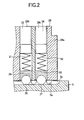
- Fig. 2 is an enlarged cross-sectional view showing a load-side end of a shaft (a detent mechanism) ;
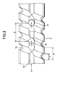
- Fig. 3 is an operation explanatory view showing the detent mechanism;
- Fig. 4 is a view of the detent mechanism when viewed from direction A shown in Fig. 3;
- Fig. 5 is a circuit diagram showing the electrical circuit of a cylinder servo motor; Fig.
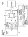
- FIG. 6 is a circuit diagram showing an electrical circuit for writing, into memory, a value for correcting an error in a ball screw pitch of the cylinder servo motor (simply called a "ball screw pitch error correction value");
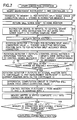
- Fig. 7 is a flowchart for describing an operation for writing the ball screw pitch error correction value into memory;
- Fig. 8 is a flowchart for describing operation of the cylinder servo motor during normal operation;
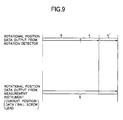
- Fig. 9 is a conceptual rendering showing computation of a ball screw pitch error correction value; and
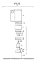
- Fig. 10 is a view showing a method of assembling the cylinder servo motor.
- the non-penetrating hole 20c is formed such that an open side is greater in diameter than a closed side by only a predetermined amount so as to enable a portion of a ball screw nut 4 to be described later to fit into the open end.
- the larger-diameter portion of the open side of the non-penetrating hole 20c extends to the load-side ball bearing 22 in the axial direction. Since the ball screw nut 4 is to be fastened to the load-side shaft end 20a of the rotary shaft 20, a shoulder section 20e is formed for securing an inner ring 22b of the load-side ball bearing 22 and an inner ring 23b of the load-side ball bearing 23.
- Reference numeral 4 designates a ball screw nut, and balls 4a of a ball circulation mechanism (not shown) are provided in an internal peripheral section of the ball screw nut 4. Further, a portion of the ball screw nut 4 is fitted into an internal peripheral section 20d of an open section of the rotary shaft 20. A flange section 4b is brought into contact with the shoulder 20e of the rotary shaft 20 and is secured on the load-side shaft end 20a of the rotary shaft 20 by means of a bolt 25 to be screw-engaged with the shoulder 20e of the rotary shaft 20.
- the detent mechanism comprises a substantially V-shaped single detent groove 5b; two steel balls 26 and 27; two ball bearings 29 and 30; springs 31 and 32; and lock screws 33 and 34.
- the detent groove 5b is formed in the vicinity of the load-side shaft end 5d of the ball screw shaft 5 in parallel with the axial direction of the ball screw shaft 5.
- the detent groove 5b has a depth substantially identical with the depth of the thread groove 5a or a depth slightly shallower than the depth of the screw thread 5a. As shown in Fig. 4, the two steel balls 26 and 27 rotate and come into contact with the detent groove 5b at two points.
- Holes 28b and 28c are formed in the end 28a of the load-side bracket 28, and the two ball bearings 29 and 30 rotatably support the steel balls 26 and 27.
- the springs 31 and 32 press the two ball bearings 29 and 30 at all times.
- the lock screws 33 and 34 are screw-threaded into the respective holes 28b and 28c formed in the end section 28a of the load-side bracket 28, thereby adjusting a rolling contact pressure between the detent groove 5b and the two steel balls 26and27, froma fasteningposition. As shown in Fig.
- the detent mechanism assumes the relationships C ⁇ 1/2P and 1.5P ⁇ B ⁇ 2P. More specifically, even when the ball screw shaft 5 is located at an arbitrary position, there is ensured a dimensional relationship such that at least one of the steel balls 26 and 27 is inevitably located in the detent groove 5b.
- outer rings 22a and 23a are fixed in the direction of the rotary shaft, by means of a housing shoulder section 28d of the load-side bracket 28 and by means of an outer ring fastening nut 39 to be screw-engaged with a female thread 28g formed in an internal peripheral wall of the load-side bracket 28.
- Inner rings 22b and 23b are fastened in the direction of the rotary shaft by a shoulder 20e of the rotary shaft 20 for securing the flange 4b of the ball screw nut 4, as well as by the inner ring fastening nut 40 to be screw-engaged with the male screw 20f of the rotary shaft 20.
- Reference numeral 41 designates an oil seal, and the oil seal 41 is fixedly fitted to an oil seal housing 28e of the load-side bracket 28.
- a lip section 41a is in contact with an outer peripheral section 4c of the flange section 4b of the ball screw nut 4.
- the cylinder servo motor is constituted of the foregoing constituent components.
- the boss 7g is fixedly fitted to the non-load-side shaft end 20b of the rotary shaft 20 projecting from the hole 38b of the non-load bracket 38. Thus, the boss 7g is rotatably fastened to the non-load-side shaft end 20b of the rotary shaft 20.
- the detection section 7a is constituted of a light-receiving section 7e which is mounted on a printed board 7d and opposes the light-emitting section 7c by way of the sign board 7f; correction memory 8; a rotation detector control section 9; and an addition/subtraction circuit 10, wherein the memory 8, the control section 9, and the circuit 10 constitute first control means, as shown in Fig. 5.
- a split angle correction value ⁇ representing the correction for each rotation of the rotation detector 7 is stored in the correction memory 8.
- a composite value consisting of the per-rotation split angle correction value ⁇ of the rotation detector 7 and a ball screw pitch ⁇ ' of the ball screw shaft 5 (a travel distance correction value used for correcting the accuracy of splitting of a travel distance of the ball screw shaft) is stored in the correction memory 8.
- the per-rotation split angle correction value ⁇ is for correcting a pitch error of a split window (not shown) provided in the sign board 7f or for correcting a per-rotation split angle error of the sign board 7f stemming from movement of the sign board 7f due to misalignment arising when the sign board 7f is attached to the rotary shaft 20.
- a central value of per-rotation split angle error of the rotation detector 7 relative to a reference split angle is sought by means of a correction value computing unit (not shown) .
- the thus-sought value is taken as a correction value.
- Reference numeral 6 designates a control device section which acts as second control means for controlling the position of the servo motor 1 and which is housed and held in a chassis 43 secured on the non-external end face 38a of the non-load-side bracket 38.
- the control device section 6 is constituted of an inverter circuit 6a, a control circuit 6b electrically connected to the inverter circuit 6a, and a power supply circuit 6c (used as a power source for the inverter circuit 6a, the control circuit 6b, and the rotation detector 7).
- the inverter circuit 6a is electrically connected to the coil 36 of the stator 3 by means of a lead wire 44, by way of a lead wire hole 38c of the non-load-side bracket 38.
- control device section 6 An electric circuit and operation of the control device section 6 are identical with those of a known control device for a servo motor. Hence, their detailed explanations are omitted here.
- a reflection mirror 11a is attached to a tip end of the ball screw shaft 5.
- a laser measurement instrument 11 is disposed so as to be able to measure a travel distance of the ball screw shaft 5.
- a controller 12 electrically connected to the laser measurement instrument 11, the correction memory 8, and a connector (not shown) (step S1 shown in Fig. 7).
- the controller 12 is constituted of a first input section 13, a second input section 14, a differential computing circuit 15, a control section 16, memory 17, and a memory writer 18.
- a home position signal is input to the control device section 6 from an instruction device 19.
- the inverter circuit 6a converts input AC power into three-phase AC power of a desired frequency, a desired voltage, and a desired current.
- the three-phase AC power is fed to the coil 36 of the stator 3 by way of the lead wire 44, thereby inducing a rotating magnetic field.
- the rotor 2 is rotated, thereby returning the servo motor 1 to its home position (step S3 shown in Fig. 7).
- the ball screw nut 4 fastened to the load-side shaft end 20a is also rotated, thereby imparting thrust to the ball screw shaft 5 by way of the balls 4a.
- the ball screw shaft 5 attempts to rotate the ball screw nut 4 by means of static friction.
- the steel balls 26 and 27 are pressed against the detent groove 5b by means of the springs 31 and 32.
- the interval B between the steel balls 26 and 27 and the dimension of the thread groove 5a assume a relationship such as that shown in Fig. 3. At least one of the steel balls 26 and 27 remains in the detent groove 5b, and hence the ball screw shaft 5 rotates directly without involving rotation of the ball screw nut 4.
- the instruction device 19 imparts to the control device section 6 an instruction signal for actuating the ball screw shaft 5 to a certain sampling point (step S4 shown in Fig. 7).
- the control device section 6 actuates the servo motor 1 in the same manner as mentioned above (step S5 shown in Fig. 7).
- the boss 7g and the sign board 7f which are fixedly fitted to the non-load-side shaft end 20b, also rotate.
- the light-receiving section 7e reads a pattern of the sign board 7f. The result of reading is converted into a photocurrent.
- the photocurrent is converted into a photo-voltage by means of an analog circuit (not shown) provided on the printed board 7d, and the photo-voltage is converted into rotational position data by means of a digital circuit (not shown) provided on the printed board 7d.
- the rotation detector control section 9 extracts the per-rotation split angle correction value ⁇ of the rotation detector 7 previously stored in the correction memory 8.
- the rotational position data are subjected to per-rotation split angle error correction in conjunction with the addition/subtraction circuit 9, through use of the correction value ⁇ (step S6 shown in Fig. 7).
- the rotation detector control section 9 When the predetermined rotational position has been achieved, the rotation detector control section 9 outputs to the control section 16 the rotational position data that have been corrected by means of the per-rotation split angle correction value ⁇ of the rotation detector 7, by way of the first input section 13 of the controller 12.
- the current position data pertaining to the ball screw shaft 5 that are obtained by means of the measuring instrument 11 measuring the light reflected from the reflection mirror 11a are output to the control section 16 by way of the second input section 14 of the controller 12 (step S10 shown in Fig. 7).
- the rotational position data ⁇ which are input to the control section 16 and have been corrected by the per-rotation split angle correction value ⁇ of the rotation detector 7 ⁇ and the current position data pertaining to the ball screw shaft 5 are output to the differential computing circuit 15 of the controller 12.
- the differential computing circuit 16 computes a ball screw pitch error correction value ⁇ ', in conjunction with the control section 16 (step S11 shown in Fig. 7).
- the thus-computed ball screw pitch error correction value ⁇ ' is temporarily stored in the memory 17.
- a+ ⁇ designates rotational position data output from the rotational detector 7.
- the rotational position data a+ ⁇ is the sum of rotational position data "a" representing a per-rotation absolute rotational position signal and a per-rotation split angle error correction value ⁇ written into the correction memory 8.
- "b" represents rotational position data obtained through conversion, by means of dividing the current positional data pertaining to the ball screw shaft 5 output from the measuring instrument 11 by the value of a lead of the ball screw.
- a ball screw pitch error correction value ⁇ ' is computed, by means of effecting computation of b-(a+ ⁇ ).
- the control section 16 fetches the per-rotation split angle correction value ⁇ of the rotational detector 7 stored in the memory 17.
- the thus-fetched split angle correction value ⁇ is combined with the previously-computed ball screw pitch error correction value ⁇ ', thereby producing a composite value ⁇ + ⁇ ' (step S12 shown in Fig. 7).
- the memory writer 18 writes the composite value into the correction memory 8 as combined correction data (step S13 shown in Fig. 7).
- the per-rotation split angle correction value ⁇ of the rotation detector 7 stored in the correction memory 8 may be deleted or left as is after all the composite values ( ⁇ + ⁇ ') have been stored into the correction memory.
- a readout address is taken into consideration such that the composite value ( ⁇ + ⁇ ') is read from the correction memory 8 and such that the thus-read composite value is used.
- the measuring instrument 11 and the controller 12 are removed from the servo motor.
- the cylinder servo motor according to the first embodiment is constructed in the manner mentioned above. During normal operation, the cylinder servo motor operates in the manner as described in the flowchart shown in Fig. 8.
- the instruction device 19 imparts to the control device section 6 an instruction signal for actuating the ball screw shaft 5 to a certain sampling point (step S20).
- the inverter circuit 6a Upon receipt of the instruction signal, the inverter circuit 6a converts input AC power into three-phase AC power of a desired frequency, a desired voltage, and a desired current.
- the three-phase AC power is fed to the coil 36 of the stator 3 by way of the lead wire 44, thereby inducing a rotatingmagnetic field.
- the servo motor 1 is actuated (step S21).
- the ball screw nut 4 fastened to the load-side shaft end 20a is also rotated, thereby imparting thrust to the ball screw shaft 5 by way of the balls 4a.
- the ball screw shaft 5 attempts to rotate the ball screw nut 4 by means of static friction.
- the steel balls 26 and 27 are pressed against the detent groove 5b by means of the springs 31 and 32.
- the interval B between the steel balls 26 and 27 and the dimension of the thread groove 5a assume a relationship such as that shown in Fig. 3. Even when the ball screw shaft 5 is situated at an arbitrary position, at least one of the steel balls 26 and 27 remains in the detent groove 5b, and hence the ball screw shaft 5 rotates directly without involving rotation of the ball screw nut 4.
- the boss 7g and the sign board 7f which are fixedly fitted to the non-load-side shaft end 20b, also rotate.
- the light-receiving section 7e reads a pattern of the sign board 7f.
- the result of reading is converted into a photocurrent.
- the photocurrent is converted into a photo-voltage by means of an analog circuit (not shown) provided on the printed board 7d, and the photo-voltage is converted into rotational position data by means of a digital circuit (not shown) provided on the printed board 7d.
- the thus-corrected rotational position data are output to the control device section 6 (step 23).
- the control device 6 compares the rotational position data with the instruction signal, thus determining whether or not the ball screw shaft 5 has arrived at a predetermined rotational position (step S24). If the ball screw shaft 5 has not yet achieved the predetermined rotational position, power is fed to the coil 36 in order to actuate the ball screw shaft 5, such that a difference becomes zero (step S25). More specifically, a general servo control operation is performed.
- the accuracy of splitting of a travel distance of the ball screw shaft 5 can be corrected at the time of control of the servo motor 1, through use of composite correction data ( ⁇ + ⁇ ') consisting of the per-rotation split angle correction value ⁇ of the rotation detector 7 and the ball screw pitch error correction value ⁇ '.
- composite correction data ⁇ + ⁇ '
- a necessity of measuring correction of an accumulated lead error in a ball screw pitch of a cylinder servo motor at a location to which the cylinder servo motor is to be shipped is obviated, and by extension there is obviated a necessity of a high-precision position measurement instrument being provided at a location to which the cylinder servo motor is to be shipped. Moreover, the time required for assembling and adjusting a machine having the cylinder servo motor built therein becomes shorter. Even when the cylinder servo motor is replaced, there is obviated a necessity of again measuring correction of an accumulated lead error in ball screw pitch at a location to which the cylinder servo motor is to be shipped.
- a necessity of wiring a line between the servo motor 1, the rotation detector 7, and the control device section 6 at a location to which the cylinder servo motor is to be shipped is obviated, thereby improving workability. Further, there is obviated a necessity of discussing a location where a controller is to be disposed, thereby improving the freedom of mechanical design.
- control device section 6 can handle a signal output from the rotation detector 7 as an ordinary signal which does not taken into account a ball screw pitch correction value used for correcting the accuracy of splitting of a travel distance of the ball screw shaft 5.
- Control load exerted on the control device section 6 for correcting the accuracy of splitting of a travel distance of the ball screw shaft 5 is small.
- a servo system realizes good trackability.
- the control device section 6 can be embodied through use of a standard device without use of a special correction circuit or amendment software. Even when the control device section 6 of the servo motor is replaced and repaired, a high degree of precision of the control device section 6 can be sustained.
- Storage means for storing a ball screw pitch error correction value to be used for correcting the accuracy of splitting of a travel distance of the ball screw shaft 5 can double as the correction memory 8 for storing a per-rotation split angle error correction value of an absolute rotation detector.
- the cylinder servo motor does not use any coupling for coupling the rotary shaft 20 with the ball screw shaft 5, which would have hitherto been employed, the cylinder servo motor becomes compact despite having a large stroke. Hence, the cylinder servo motor is wholly made compact, and the number of components is reduced.
- the previously-described components can be assembled from one direction, thereby improving the ease of assembly of a cylinder servo motor.
- the lip section 41a of the oil seal 41 is in contact with the outer peripheral surface 4c of the fastening flange 4b of the ball screw nut 4. Hence, the dimension of the oil seal section can be shortened in the axial direction, thereby rendering the cylinder servo motor more compact.
- the detent mechanism makes rolling contact, abrasion of a contact surface is diminished, thereby prolonging the life span of the detection mechanism and reducing friction loss (by extension, input power is diminished, and energy savings is attained).
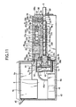
- FIG. 11 is a fragmentary longitudinal cross-sectional view of a cylinder servo motor
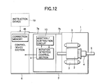
- Fig. 12 is a schematic diagram showing the configuration of an electric circuit of the cylinder servo motor
- Fig. 13 is a schematic diagram showing the configuration of an electric circuit required for writing into memory a ball screw pitch error correction value of the cylinder servo motor
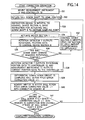
- Fig. 14 is a flowchart for describing the operation of the cylinder servo motor when the ball screw pitch error correction value is written into memory
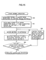
- Fig. 15 is a flowchart for describing the operation of the cylinder servo motor during a normal operation
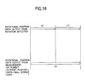
- Fig. 16 is a conceptual computation rendering of the ball screw pitch error correction value.
- reference numeral 46 designates correction memory incorporated into the control device section 6.
- a ball screw pitch error ⁇ 1' i.e., a travel distance correction value for correcting the accuracy of splitting of a travel distance of a ball screw shaft
- the manner of storing the ball screw pitch error ⁇ 1' will be described later.
- the cylinder servo motor according to the present embodiment is substantially identical in configuration with that described in connection with the first embodiment, and hence repeated explanation is omitted.
- the reflection mirror 11a is attached to a tip end of the ball screw shaft 5, as shown in Fig. 13. Further, the laser measurement instrument 11 is disposed so as to be able to measure a travel distance of the ball screw shaft 5. Further, there is disposed the controller 12 electrically connected to the laser measurement instrument 11, the correction memory 8, and a connector (not shown) (step S31 shown in Fig. 14).
- the controller 12 is constituted of the first input section 13, the second input section 14, the differential computing circuit 15, the control section 16, the memory 17, and the memory writer 18.
- Power of the control device section 6 is turned on, to thereby activate the inverter circuit 6a, the control circuit 6b, and the rotation detector 7. Further, the laser measurement instrument 11 and the controller 12 are turned on and activated.
- a home position signal is input to the control device section 6 from an instruction device 19.
- the inverter circuit 6a converts input AC power into three-phase AC power of a desired frequency, a desired voltage, and a desired current.
- the three-phase AC power is fed to the coil 36 of the stator 3 by way of the lead wire 44, thereby inducing a rotating magnetic field.
- the rotor 2 is rotated, thereby returning the servo motor 1 to its home position (step S32 shown in Fig. 14).
- the ball screw nut 4 fastened to the load-side shaft end 20a is also rotated, thereby imparting thrust to the ball screw shaft 5 by way of the balls 4a.
- the ball screw shaft 5 attempts to rotate the ball screw nut 4 by means of static friction.
- the steel balls 26 and 27 are pressed against the detent groove Sbbymeans of the springs 31 and 32.
- the interval B between the steel balls 26 and 27 and the dimension of the thread groove 5a assume a relationship such as that shown in Fig. 3.
- the instruction device 19 imparts to the control device section 6 an instruction signal for actuating the ball screw shaft 5 to a certain sampling point (step S33 shown in Fig. 14).
- the control device section 6 actuates the servo motor 1 in the same manner as mentioned above (step S34 shown in Fig. 14).
- the boss 7g and the sign board 7f which are fixedly fitted to the non-load-side shaft end 20b, also rotate.
- the light-receiving section 7e reads a pattern of the sign board 7f.
- the result of reading is converted into a photocurrent.
- the photocurrent is converted into a photo-voltage by means of an analog circuit (not shown) provided on the printed board 7d, and the photo-voltage is converted into rotational position data by means of a digital circuit (not shown) provided on the printed board 7d.
- the rotational position data are output to the control device section 6 (step S35 shown in Fig. 14).
- the control device 6 compares the rotational position data with the instruction signal, thus determining whether or not the ball screw shaft 5 has arrived at a predetermined rotational position (step S36 shown in Fig. 14). If the ball screw shaft 5 has not yet achieved the predetermined rotational position, power is fed to the coil 36 in order to actuate the ball screw shaft 5, such that a difference becomes zero (step S37 shown in Fig. 14). More specifically, a general servo control operation is performed.
- the rotation detector control section 9 When the predetermined rotational position has been achieved, the rotation detector control section 9 outputs to the control section 16 the rotational position data by way of the first input section 13 of the controller 12.
- the current position data pertaining to the ball screw shaft 5, which are obtained by means of the measuring instrument 11 measuring the light reflected from the reflection mirror 11a, are output to the control section 16 by way of the second input section 14 of the controller 12 (step S38 shown in Fig. 14).
- the rotational position data input to the control section 16 and the current position data pertaining to the ball screw shaft 5 are output to the differential computing circuit 15 of the controller 12.
- the differential computing circuit 16 computes a ball screw pitch error correction value ⁇ 1', in conjunction with the control section 16 (step S39 shown in Fig. 14).
- the thus-computed ball screw pitch error correction value ⁇ 1' is temporarily stored in the memory 17.
- a1 designates rotational position data representing a per-rotation absolute rotational position signal output from the rotation detector 7.
- "b1" represents rotational position data obtained through conversion by means of dividing the current positional data pertaining to the ball screw shaft 5 output from the measuring instrument 11 by the value of a lead of the ball screw.
- a ball screw pitch error correction value ⁇ 1' is computed, by means of effecting computation of b1-a1.
- the control section 16 fetches the ball screw pitch error correction value ⁇ 1' temporarily stored in the memory 17.
- the memory writer 18 writes the ball screw pitch error correction value ⁇ 1' into the correction memory 46 provided in the control device section 6 (step S40 shown in Fig. 14).
- the ball screw pitch error ⁇ 1' of the ball screw shaft 5 is stored in the correction memory 46 before shipment of a cylinder servo motor product.
- the measurement instrument 11 and the controller 12 are removed from the cylinder servo motor.
- the cylinder servo motor according to the second embodiment of the present invention is constituted in the manner as mentioned above, the cylinder servo motor operates according to a flowchart shown in Fig. 15 during normal operation.
- the instruction device 19 imparts to the control device section 6 an instruction signal for actuating the ball screw shaft 5 to a certain sampling point (step S50).
- the control device section 6 fetches the ball screw pitch error ⁇ 1' from the correction memory 46, and the thus-fetched error is added to the instruction signal (step S51). More specifically, a signal which is the sum of the instruction value imparted from the instruction device 19 and the ball screw pitch error ⁇ 1' is taken as an instruction value to be sent to a motor.
- the inverter circuit 6a converts input AC power into three-phase AC power of a desired frequency, a desired voltage, and a desired current.
- the three-phase AC power is fed to the coil 36 of the stator 3 by way of the lead wire 44, thereby inducing a rotating magnetic field.
- the servo motor 1 is actuated (step S52).
- the ball screw nut 4 fastened to the load-side shaft end 20a is also rotated, thereby imparting thrust to the ball screw shaft 5 by way of the balls 4a.
- the ball screw shaft 5 attempts to rotate the ball screw nut 4 by means of static friction.
- the steel balls 26 and 27 are pressed against the detent groove 5b by means of the springs 31 and 32. Further, the interval B between the steel balls 26 and 27 and the dimension of the thread groove 5a assume a relationship such as that shown in Fig. 3. Even when the ball screw shaft 5 is situated at an arbitrary position, at least one of the steel balls 26 and 27 remains in the detent groove 5b, and hence the ball screw shaft 5 rotates directly without involving rotation of the ball screw nut 4.
- the boss 7g and the sign board 7f which are fixedly fitted to the non-load-side shaft end 20b, also rotate.
- the light-receiving section 7e reads a pattern of the sign board 7f.
- the result of reading is converted into a photocurrent.
- the photocurrent is converted into a photo-voltage by means of an analog circuit (not shown) provided on the printed board 7d, and the photo-voltage is converted into rotational position data by means of a digital circuit (not shown) provided on the printed board 7d.
- step S53 the thus-corrected rotational position data are output to the control device section 6 (step S53).
- the control device 6 compares the rotational position data with the instruction signal (to which the ball screw pitch error ⁇ 1' has been added) , thus determining whether or not the ball screw shaft 5 has arrived at a predetermined rotational position (step S54). If the ball screw shaft 5 has not yet achieved the predetermined rotational position, power is fed to the coil 36 in order to actuate the ball screw shaft 5, such that a difference becomes zero (step S55). More specifically, a general servo control operation is performed.
- the rotational position data which has been corrected through use of the per-rotation split angle correction value ⁇ of the rotation detector 7 maybe employed as the rotational position data output from the rotation detector 7, in the same manner as in the first embodiment.
- the ball screw pitch error correction value ⁇ 1' to be stored in the correction memory 46 corresponds to data determined by subtracting (rotational position data taking into account the per-rotation split angle correction value ⁇ of the rotation detector 7) from (data obtained by means of dividing the current positional data pertaining to the ball screw shaft 5 output from the measurement instrument 11 by the ball screw lead and converting the result of division into rotational position data).
- the accuracy of splitting of a travel distance of the ball screw shaft 5 can be corrected at the time of control of the servo motor 1, through use of the ball screw pitch error correction value ⁇ 1'.
- a high-precision cylinder servo motor can be provided.
- a necessity of measuring correction of an accumulated lead error in a ball screw pitch of a cylinder servo motor at a location to which the cylinder servo motor is to be shipped is obviated, and by extension there is obviated a necessity of providing a high-precision position measurement instrument at a location to which the cylinder servo motor is to be shipped. Moreover, the time required for assembling and adjusting a machine having the cylinder servo motor built therein becomes shorter. Even when the cylinder servo motor is replaced, there is obviated a necessity of again measuring correction of an accumulated lead error in ball screw pitch at a location to which the cylinder servo motor is to be shipped.
- a necessity of wiring a line between the servo motor 1, the rotation detector 7, and the control device section 6 at a location to which the cylinder servo motor is to be shipped is obviated, thereby improving workability. Further, there is obviated a necessity of discussing a location where a controller is to be disposed, thereby improving the freedom of mechanical design.
- the absolute rotation detector 7 Since the absolute rotation detector 7 is used, the position of the ball screw shaft is backed up even when power is turned off. Hence, there is no necessity of returning the ball screw shaft 5 to its home position. An output from the rotation detector 7 and the ball screw pitch error correction value ⁇ 1' for correcting the accuracy of splitting a travel distance of the ball screw shaft 5 can be handled simultaneously. Since the servo motor section can be controlled on the basis of the position of a correct magnetic pole, good efficiency is achieved. Further, high-precision control of the cylinder servo motor can be effected, through use of the ball screw pitch error correction value ⁇ 1'used for correcting the accuracy of splitting of a travel distance of the ball screw shaft 5.
- the cylinder servo motor does not use any coupling for coupling the rotary shaft 20 with the ball screw shaft 5, which would have hitherto been employed, the cylinder servo motor becomes compact despite having a large stroke. Hence, the cylinder servo motor is wholly made compact, and the number of components is reduced.
- the electric circuit of the rotation detector 7 is doubly covered by the rotation detector cover 42 and the chassis 43. Further, a hole is formed in the rotary shaft 20, and the hole is the non-penetrating hole 20c. Thus, good airtightness is ensured, and reliability of the cylinder servo motor against an external environment is improved.
- the previously-described components can be assembled from one direction, thereby improving the ease of assembly of a cylinder servo motor. More specifically, in relation to the load-side bracket 28 having a detent mechanism and the oil seal 41 incorporated therein beforehand, there can be sequentially assembled the rotor 2 having the ball screw nut 4 and the ball screw shaft 5 incorporated therein beforehand, the load-side ball bearings 22 and 23, the non-load-side ball bearing 24, the inner ring fastening nut 40, the outer ring fastening nut 39, the stator 3, the non-load-side bracket 38, the absolute rotation detector 7, and the control device section 6.
- the lip section 41a of the oil seal 41 is in contact with the outer peripheral surface 4c of the fastening flange 4b of the ball screw nut 4. Hence, the dimension of the oil seal section can be shortened in the axial direction, thereby rendering the cylinder servo motor more compact.
- the detent mechanism makes rolling contact, abrasion of a contact surface is diminished, thereby prolonging the life span of the detection mechanism and reducing friction loss (by extension, input power is diminished, and energy savings is attained).
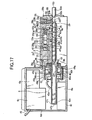
- FIG. 17 is a fragmentary longitudinal cross-sectional view of a cylinder servo motor
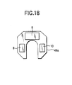
- Fig. 18 is a diagram showing the geometry of a printed board used in the rotation detector.
- a non-load-side shaft end 47b of a rotary shaft 47 penetrates through an absolute rotation detector 49 (corresponding to the absolute rotation detector 7 described in connection with the first embodiment) and extends to the neighborhood of an end section 6d of the control device section 6.
- an absolute rotation detector 49 corresponding to the absolute rotation detector 7 described in connection with the first embodiment
- a non-load-side shaft end 50c of a ball screw shaft 50 is extended to the neighborhood of the non-load-side shaft end 47b of the rotary shaft 47.
- a printed board 49d of the rotation detector 49 is formed to assume a C-shaped geometry as shown in Fig. 18, and a hole is formed in a rotation detector cover 52 (corresponding to the rotation detector cover 42 described in connection with the first embodiment) so that the rotary shaft 47 can penetrate through the hole.
- the cylinder servo motor according to the third embodiment is identical in operation with that described in connection with the first embodiment.
- the ball screw shaft 50 corresponding to the ball screw shaft 5 is actuated to a predetermined position.
- the third embodiment can be applied to the second embodiment.
- the third embodiment also yields an advantage of the ability to realize a stroke of longer linear movement even when a cylinder servo motor of a given dimension is employed.
- FIG. 19 i.e., a fragmentary longitudinal cross-sectional view showing a cylinder servo motor.
- a non-load-side shaft end 53b of a rotary shaft 53 penetrates through the rotation detector 49 and is extended to the neighborhood of the end section 6d of the control device section 6.
- a through hole 53c is formed in the rotary shaft 53 so as to extend from a load-side shaft end 53a to the non-load-side shaft end 53b in the direction of the rotary shaft 53.
- the non-load-side shaft end 50c of the ball screw shaft 50 is extended to the neighborhood of the non-load-side shaft end 53b of the rotary shaft 53.
- a printed board 49d of the rotation detector 49 is produced into a C-shaped form, as shown in Fig. 18. Further, a hole through which the rotary shaft 53 can penetrate is formed in the rotation detector cover 52.
- a female thread 53g is formed inside the non-load-side shaft end 53b of the through hole 53c.
- a through hole cover 54 having a male screw formed thereon is removably screw-engaged with the female thread 53g, thereby closing the non-load-side shaft end 53b of the through hole 53c.
- a through hole 43a opposing the through hole cover 54 is formed in the end 6d of the chassis 43, and a removable sealing cover 43b is attached to the through hole 43a.
- a female thread 50d is axially provided on the non-load-shaft end 50c of the ball screw shaft 50.
- the through hole cover 54 is provided for preventing entry of oil or an oil mist from the through hole 53c of the non-load-side shaft end 53b of the rotary shaft 53. Further, the sealing cover 43b is provided for preventing entry of dust into the through hole 43a of the chassis 43, which would otherwise cause deterioration of the rotation section 49b of the rotation detector 49 in an external environment.
- good reliability of the cylinder servo motor against the external environment i.e., the same advantage as described in connection with the first through third embodiments, can be maintained.
- the cylinder servo motor according to the present embodiment is substantially identical in configuration with that described in connection with the third embodiment, and hence repeated explanation thereof is omitted.
- the sealing cover 43b is removed from the chassis 43 while the cylinder servo motor is mounted on a machine (not shown). Subsequently, the through hole cover 54 is removed, and an adjustment jig (not shown) on which is formed a male screw to be screw-engaged with the female thread 50d formed on the non-load-side shaft end 50c of the ball screw shaft 50 is attached to the ball screw shaft 50. The adjustment jig is manually pushed and pulled, thereby enabling direct, manual actuation of the ball screw shaft 50.
- the cylinder servo motor operates in the same manner as in the third embodiment.
- the ball screw shaft 50 is actuated to a predetermined position.
- the fourth embodiment yields an advantage of the ability to enable manual positioning of the ball screw shaft 50 while the cylinder servo motor is mounted on a machine, thereby improving the workability and operability of the cylinder servo motor.
- FIG. 20 i.e., a fragmentary longitudinal cross-sectional view of the cylinder servo motor
- the oil seal 41 is fixedly fitted to an oil seal housing 28f of the load-side bracket 28.
- a lip section 41a of the oil seal 41 which is smaller in diameter than the outer peripheral section 4c of the flange section 4b of the ball screw nut 4, remains in contact with an external outer peripheral surface 4d of the ball screw nut 4.
- the cylinder servo motor according to the present embodiment is substantially identical in configuration with that described in connection with the first embodiment, repeated explanation thereof is omitted. Moreover, the cylinder servo motor according to the present embodiment is substantially identical in operation with that described in connection with the first embodiment.
- the fifth embodiment can be applied also to the second through fourth embodiments.
- the fifth embodiment yields an advantage of the ability to improve the abrasion resistance of the oil seal 41 and to prolong the life span of the cylinder servo motor.
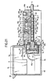
- FIG. 21 is a fragmentary longitudinal cross-sectional view showing a cylinder servo motor.
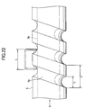
- Fig. 22 is an operation descriptive view of the detent mechanism of the cylinder servo motor.
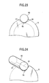
- Fig. 23 is a view from direction B shown in Fig. 22.
- Fig. 24 is a perspective view showing that the detent mechanism of the cylinder servo motor according to the fifth embodiment is in a contact state.
- the detent mechanism comprises a substantially V-shaped single detent groove 5b; one cylindrical roller 60; one roller bearing 59; a spring 58 for pressing the cylindrical roller 60 at all times; and a lock screw 57.
- the V-shaped single detent groove 5b is formed in the neighborhood of the load-side shaft end 5d of the ball screw shaft 5 and in parallel with the axial direction of the ball screw shaft 5.
- the detent groove 5b has a depth substantially identical with the depth of the thread groove 5a or a depth slightly shallower than the depth of the screw thread 5a. As shown in Fig. 23, the cylindrical roller 60 comes into contact with the detent groove 5b at two contact points 61 and 62.
- the roller bearing 59 is provided in a hole 56b formed in an end section 56a of the load-side bracket 56 (corresponding to the load-side bracket 28 described in connection with the first embodiment) .
- the roller bearing 59 rotatably supports the cylindrical roller 60.
- the lock screw 57 is screw-engaged with the hole 56b formed in the end section 56a of the load-side bracket 56 and adjusts a rolling contact pressure arising between the detent groove 5b and the cylindrical roller 60 from a fastening position.
- a pitch of the thread groove 5a is taken as P
- the width of the thread groove 5a is taken as C
- the length of the cylindrical roller is taken as L
- the detent mechanism assumes a relationship 2C ⁇ L ⁇ P. More specifically, even when the ball screw shaft 5 is located at an arbitrary position, there is ensured a dimensional relationship such that a portion of the cylindrical roller 60 is located in the detent groove 5b at all times.
- the housing shoulder 56d, the oil seal housing 56e, and the female thread 56g correspond to the housing shoulder 28d, the oil seal housing 28e, and the female thread 56g described in connection with the first embodiment.
- the cylinder servo motor according to the present embodiment is substantially identical in configuration with that described in connection with the first embodiment, and hence repeated explanation thereof is omitted.
- detent mechanism described in the sixth embodiment can be replaced with any of those described in connection with the second through fifth embodiments.
- the sixth embodiment yields an advantage of the ability to reduce the overall length of the cylinder servo motor, because only one detection mechanism provided in the axial direction of the rotary shaft acts as a whirl stop.
- the detent mechanism is disposed in parallel with and in line with the axial direction. If at least one ball to be brought into contact with a detent groove is located in a section where the ball does not cross the detent groove, the number of detent grooves to be formed in the ball screw shaft 5 may be increased such that two detent grooves are provided so as to oppose each other or such that a plurality of detent grooves are provided radially.
- the reflectionmirror 11a is attached to the tip end of the ball screw shaft 5, thereby measuring a travel distance.
- the tip end of the ball screw shaft 5 is machined into a mirrored surface by means of abrasion, the mirror 11a becomes unnecessary. Needless to say, a necessity of removing the mirror 11a after measurement becomes obviated.
- the first through sixth embodiments have described the built-in control device section 6.
- the control device section 6 is identified by an ID code, and the cylinder servo motor is always used in one-to-one correspondence with the control device section 6, then the control device section 6 may be separated rather than incorporated.
- a cylinder servo motor main unit, a detector, and a control device section are referred to as being integrated.
- the present invention provides a cylinder servo motor comprising:
- a necessity of measuring correction of an accumulated lead error in a ball screw pitch of a cylinder servo motor at a location to which the cylinder servo motor is to be shipped is obviated, and by extension there is obviated a necessity of a high-precision position measurement instrument being provided at a location to which the cylinder servo motor is to be shipped. Moreover, the time required for assembling and adjusting a machine having the cylinder servo motor built therein becomes shorter. Even when the cylinder servo motor is replaced, there is obviated a necessity of again measuring correction of an accumulated lead error in ball screw pitch at a location to which the cylinder servo motor is to be shipped.
- a necessity of wiring a line between the servo motor, the rotation detector, and the control device section at a location to which the cylinder servo motor is to be shipped is obviated, thereby improving workability.
- the storage means for storing the travel distance correction value is provided on the control means for controlling the rotation detector.
- the storage means for storing the travel distance correction value is provided on the control means for controlling the servo motor.
- the present invention also provides cylinder servo motor comprising:
- the storage means for storing a per-rotation split angle error correction value of the absolute rotation detector can be used also as the storage means for storing the travel distance correction value to be used for correcting the accuracy of splitting of a travel distance of a ball screw shaft.
- the present invention also provides a cylinder servo motor comprising:
- the rotor of the servo motor is constituted of the rotary shaft and a permanent magnet, the rotary shaft being rotatably supported by a load-side bearing supported by a load-side bracket and by a non-load-side bearing supported by a non-load-side bracket, at least the load-side end of the rotary shaft being released, a through hole being formed in the rotary shaft so as to extend in an axial direction, and the permanent magnet being disposed opposite the stator fixed to the rotary shaft with a predetermined clearance therebetween.
- the ball screw nut is constituted of a ball circulation mechanism and is mounted on a load-side shaft end of the rotary shaft.
- the ball screw shaft is screw-engaged with the ball screw nut so as to become movable in only the axial direction such that a non-load-side shaft end of the ball screw shaft is housed in the through hole of the rotary shaft and such that a load-side end of the ball screw shaft protrudes from the load-side bracket.
- a rotation portion of the rotation sensor is coupled to a non-load-side portion of the rotary shaft protruding from the hole formed in the non-load-side bracket and is covered with a rotation sensor cover.
- the control means of the servo motor is disposed on a part of the non-load-side bracket distant from the stator, and the control means and the rotation sensor cover are covered with a chassis to be fastened to the non-load-side bracket.
- the cylinder servo motor becomes compact despite having a long stroke. Hence, the cylinder servo motor is made compact overall, and the number of components is reduced.
- the rotation portion of the rotation sensor is doubly covered by the rotation sensor cover and the chassis. Accordingly, reliability of the cylinder servo motor against an external environment is improved.
- the non-load-side end of the rotary shaft and the through hole are elongated to a position where the control means of the servo motor is disposed. Further, in association with elongation of the non-load-side end and elongation of the through hole, the non-load-side shaft end of the ball screw shaft is elongated.
- a non-load-side of the through hole of the rotary shaft is opened, and a cover for covering the open side is removably provided.
- a through hole is formed in a portion of the chassis opposing the cover with reference to an axial direction of the rotary shaft.
- the through hole formed in the chassis is provided with a removable cover.
- the load-side shaft bearing is constituted of a ball bearing.
- An outer ring of the ball bearing is fixedly sandwiched between a shoulder section formed on an internal peripheral wall of the load-side bracket and an outer ring fastening nut to be screw-engaged with an internal peripheral wall of the load-side bracket.
- An inner ring of the ball bearing is fixedly sandwiched between a ball screw nut fastening shoulder section formed on the load-side shaft end of the rotary shaft of the servo motor and an inner ring fastening nut to be screw-engaged with the rotary shaft of the servo motor.
- An inner diameter of the inner ring of the ball bearing is made greater than an outer diameter of the rotor of the servo motor.
- the ball screw nut fastening shoulder is formed on the load-side shaft end of the rotary shaft, and a fastening flange section is formed on the ball screw nut.
- a portion of the ball screw nut is fitted into the through hole formed in the load-side shaft end of the rotary shaft.
- the fastening flange section is brought into contact with and screw-engagedwith the ball screw nut fastening shoulder section.
- the ball screw nut is fastened to the load-side shaft end of the rotary shaft, and an oil seal is held on the load-side bracket.
- a lip section of the oil seal is brought into contact with an outer peripheral surface of the ball screw nut fastening flange.
- a ball screw nut fastening shoulder is formed on a load-side shaft end of the rotary shaft, and a fastening flange section is formed at a position closer to the center of the ball screw nut.
- a portion of the ball screw nut is fitted into a through hole section formed in the load-side shaft end of the rotary shaft, and the fastening flange section is brought into contact with and screw-engaged with the ball screw nut fastening shoulder section.
- the ball screw nut is fastened to the load-side shaft end of the rotary shaft, and an oil seal is held on the load-side bracket.
- a lip section of the oil seal is brought into contact with an outer peripheral surface at the shaft end of the ball screw nut.
- the present invention yields an advantage of the ability to improve abrasion resistance of the oil seal and elongate the life span of the cylinder servo motor, because a sliding diameter of the lip section of the oil seal becomes smaller and a circumferential speed of a contact section becomes low.
- a detent groove is formed in an outer peripheral section of the ball screw shaft, wherein the detent groove has substantially the same depth as that of a thread groove or a depth shallower than that of the thread groove and extends in an axial direction.
- the ball screw shaft has at least two balls to be inserted into the detent groove, and a spring for pressing the balls toward the detent groove at all times. The balls are disposed such that at least one of the balls is situated in the detent groove at all times.
- the present invention yields an advantage of diminishing abrasion of the contact surface, thereby prolonging the life span of a whirl stop and diminishing friction loss of the whirl stop (by extension, input power is diminished, thereby realizing energy savings), because the whirl stop makes rolling contact.
- a detent groove is formed in an outer peripheral section of the ball screw shaft, wherein the detent groove has substantially the same depth as that of a thread groove or a depth shallower than that of the thread groove and extends in an axial direction.
- the ball screw shaft has at least one cylindrical roller which is to be inserted into the detent groove and is longer than a screw pitch of the ball screw shaft, and a spring for pressing the cylindrical ball toward the detent groove at all times.
- a cylinder servo motor according to the present invention is suitable for use with a measuring instrument, a spot welding machine, an NC machine, and a plant.
Landscapes
- Engineering & Computer Science (AREA)
- Power Engineering (AREA)
- Microelectronics & Electronic Packaging (AREA)
- Transmission Devices (AREA)
- Connection Of Motors, Electrical Generators, Mechanical Devices, And The Like (AREA)
Applications Claiming Priority (1)
| Application Number | Priority Date | Filing Date | Title |
|---|---|---|---|
| PCT/JP2000/001117 WO2001063730A1 (fr) | 2000-02-25 | 2000-02-25 | Servomoteur cylindrique |
Publications (1)
| Publication Number | Publication Date |
|---|---|
| EP1189331A1 true EP1189331A1 (fr) | 2002-03-20 |
Family
ID=11735725
Family Applications (1)
| Application Number | Title | Priority Date | Filing Date |
|---|---|---|---|
| EP00905361A Withdrawn EP1189331A1 (fr) | 2000-02-25 | 2000-02-25 | Servomoteur cylindrique |
Country Status (2)
| Country | Link |
|---|---|
| EP (1) | EP1189331A1 (fr) |
| WO (1) | WO2001063730A1 (fr) |
Cited By (3)
| Publication number | Priority date | Publication date | Assignee | Title |
|---|---|---|---|---|
| US6570282B1 (en) * | 2000-02-25 | 2003-05-27 | Mitsubishi Denki Kabushiki Kaisha | Cylinder servomotor |
| CN108475964A (zh) * | 2016-01-27 | 2018-08-31 | Ntn株式会社 | 电动致动器 |
| US11766778B2 (en) | 2021-07-19 | 2023-09-26 | Nsk Ltd. | Driving device and method for controlling the same, and parallel link robot and method for controlling the same |
Families Citing this family (5)
| Publication number | Priority date | Publication date | Assignee | Title |
|---|---|---|---|---|
| US6979971B2 (en) | 2001-04-26 | 2005-12-27 | Mitsubishi Denki Kabushiki Kaisha | Control device-built-in cylinder servo motor |
| WO2023002642A1 (fr) * | 2021-07-19 | 2023-01-26 | 日本精工株式会社 | Dispositif d'entraînement, procédé de commande de dispositif d'entraînement, robot à liaison parallèle et procédé de commande de robot à liaison parallèle |
| JP2023148678A (ja) * | 2022-03-30 | 2023-10-13 | 日立Astemo上田株式会社 | 電動アクチュエータおよびそれを備えた液圧発生装置 |
| CN119362839B (zh) * | 2024-12-20 | 2025-03-14 | 江苏惠斯通机电科技有限公司 | 一种低噪音气动型真空步进电机 |
| CN120103144B (zh) * | 2025-05-07 | 2025-08-01 | 常州鑫鼎机电设备有限公司 | 一种双丝杠同步驱动式直线电机测试平台 |
Family Cites Families (7)
| Publication number | Priority date | Publication date | Assignee | Title |
|---|---|---|---|---|
| JPH0182655U (fr) * | 1988-11-17 | 1989-06-01 | ||
| JPH033692A (ja) * | 1989-05-29 | 1991-01-09 | Secoh Giken Inc | 負荷の数値制御装置 |
| JPH03120663U (fr) * | 1990-03-20 | 1991-12-11 | ||
| JP3052573B2 (ja) * | 1992-04-30 | 2000-06-12 | 神鋼電機株式会社 | ダイレクト・ドライブ式のアウタロ−タ形回転電機 |
| JPH07123631A (ja) * | 1993-10-22 | 1995-05-12 | Teijin Seiki Co Ltd | 電動アクチュエータ |
| JP3143310B2 (ja) * | 1994-02-25 | 2001-03-07 | 三菱電機株式会社 | 位置検出装置、補正機能付位置検出装置、位置検出方法、および、位置検出装置の補正方法 |
| JPH10271763A (ja) * | 1997-03-25 | 1998-10-09 | Toshiba Corp | 制御装置付モータ及び永久磁石モータ |
-
2000
- 2000-02-25 EP EP00905361A patent/EP1189331A1/fr not_active Withdrawn
- 2000-02-25 WO PCT/JP2000/001117 patent/WO2001063730A1/fr not_active Ceased
Non-Patent Citations (1)
| Title |
|---|
| See references of WO0163730A1 * |
Cited By (5)
| Publication number | Priority date | Publication date | Assignee | Title |
|---|---|---|---|---|
| US6570282B1 (en) * | 2000-02-25 | 2003-05-27 | Mitsubishi Denki Kabushiki Kaisha | Cylinder servomotor |
| CN108475964A (zh) * | 2016-01-27 | 2018-08-31 | Ntn株式会社 | 电动致动器 |
| CN108475964B (zh) * | 2016-01-27 | 2020-07-28 | Ntn株式会社 | 电动致动器 |
| US10830320B2 (en) | 2016-01-27 | 2020-11-10 | Ntn Corporation | Electric actuator |
| US11766778B2 (en) | 2021-07-19 | 2023-09-26 | Nsk Ltd. | Driving device and method for controlling the same, and parallel link robot and method for controlling the same |
Also Published As
| Publication number | Publication date |
|---|---|
| WO2001063730A1 (fr) | 2001-08-30 |
Similar Documents
| Publication | Publication Date | Title |
|---|---|---|
| US6570282B1 (en) | Cylinder servomotor | |
| US5525885A (en) | Position detecting apparatus and position compensating method therefor | |
| EP0671070B1 (fr) | Actionneur a translation avec capteur de position a retroaction | |
| CN107662221B (zh) | 一种机械臂关节 | |
| EP1189331A1 (fr) | Servomoteur cylindrique | |
| US8453530B2 (en) | Linear actuator | |
| KR100514158B1 (ko) | 사출장치 | |
| EP4349547B1 (fr) | Bras de robot collaboratif et module d'articulation | |
| US20050257991A1 (en) | Electric power steering apparatus | |
| CN102501226B (zh) | 一种宏微驱动变形导轨精密回转装置 | |
| US20210218314A1 (en) | Electric motor having a rotor shaft and a first and a second bearing | |
| EP3795859A1 (fr) | Actionneur linéaire | |
| KR102642587B1 (ko) | 전기 실린더용 모터 및 모터용 인코더 | |
| CN114555290A (zh) | 旋转定位装置 | |
| CN110868013B (zh) | 一种直线作动器及其控制方法 | |
| CN119458445B (zh) | 一种“电机-螺母-轴承”一体化设计的直线关节 | |
| CN120433637A (zh) | 一种无刷行星机器人关节电机及其多位置反馈与控制方法 | |
| JP2008538415A (ja) | ねじりモーメントの測定装置および方法 | |
| JP3690339B2 (ja) | 回転変位検出装置の組付け構造 | |
| JPWO2001063730A1 (ja) | シリンダサーボモータ | |
| US20230137763A1 (en) | Linear electromechanical actuator | |
| CN219726298U (zh) | 一种码盘安装结构、关节模组及其机器人 | |
| US20250293573A1 (en) | Actuator | |
| JP3364806B2 (ja) | リニアアクチュエータ | |
| JP4992182B2 (ja) | 回転機構付軸方向微動装置 |
Legal Events
| Date | Code | Title | Description |
|---|---|---|---|
| PUAI | Public reference made under article 153(3) epc to a published international application that has entered the european phase |
Free format text: ORIGINAL CODE: 0009012 |
|
| 17P | Request for examination filed |
Effective date: 20011025 |
|
| AK | Designated contracting states |
Kind code of ref document: A1 Designated state(s): AT BE CH CY DE DK ES FI FR GB GR IE IT LI LU MC NL PT SE |
|
| STAA | Information on the status of an ep patent application or granted ep patent |
Free format text: STATUS: THE APPLICATION HAS BEEN WITHDRAWN |
|
| 18W | Application withdrawn |
Effective date: 20030123 |