EP1189356A1 - Appareil communiquant multimodes comportant un dispositif d'émission réception à plusieurs entrées - Google Patents
Appareil communiquant multimodes comportant un dispositif d'émission réception à plusieurs entrées Download PDFInfo
- Publication number
- EP1189356A1 EP1189356A1 EP01000421A EP01000421A EP1189356A1 EP 1189356 A1 EP1189356 A1 EP 1189356A1 EP 01000421 A EP01000421 A EP 01000421A EP 01000421 A EP01000421 A EP 01000421A EP 1189356 A1 EP1189356 A1 EP 1189356A1
- Authority
- EP
- European Patent Office
- Prior art keywords
- signals
- port
- reception
- selector
- chain
- Prior art date
- Legal status (The legal status is an assumption and is not a legal conclusion. Google has not performed a legal analysis and makes no representation as to the accuracy of the status listed.)
- Granted
Links
Images

Classifications
-
- H—ELECTRICITY
- H04—ELECTRIC COMMUNICATION TECHNIQUE
- H04B—TRANSMISSION
- H04B1/00—Details of transmission systems, not covered by a single one of groups H04B3/00 - H04B13/00; Details of transmission systems not characterised by the medium used for transmission
- H04B1/005—Details of transmission systems, not covered by a single one of groups H04B3/00 - H04B13/00; Details of transmission systems not characterised by the medium used for transmission adapting radio receivers, transmitters andtransceivers for operation on two or more bands, i.e. frequency ranges
- H04B1/0053—Details of transmission systems, not covered by a single one of groups H04B3/00 - H04B13/00; Details of transmission systems not characterised by the medium used for transmission adapting radio receivers, transmitters andtransceivers for operation on two or more bands, i.e. frequency ranges with common antenna for more than one band
- H04B1/006—Details of transmission systems, not covered by a single one of groups H04B3/00 - H04B13/00; Details of transmission systems not characterised by the medium used for transmission adapting radio receivers, transmitters andtransceivers for operation on two or more bands, i.e. frequency ranges with common antenna for more than one band using switches for selecting the desired band
-
- H—ELECTRICITY
- H04—ELECTRIC COMMUNICATION TECHNIQUE
- H04B—TRANSMISSION
- H04B1/00—Details of transmission systems, not covered by a single one of groups H04B3/00 - H04B13/00; Details of transmission systems not characterised by the medium used for transmission
- H04B1/005—Details of transmission systems, not covered by a single one of groups H04B3/00 - H04B13/00; Details of transmission systems not characterised by the medium used for transmission adapting radio receivers, transmitters andtransceivers for operation on two or more bands, i.e. frequency ranges
-
- H—ELECTRICITY
- H04—ELECTRIC COMMUNICATION TECHNIQUE
- H04B—TRANSMISSION
- H04B1/00—Details of transmission systems, not covered by a single one of groups H04B3/00 - H04B13/00; Details of transmission systems not characterised by the medium used for transmission
- H04B1/38—Transceivers, i.e. devices in which transmitter and receiver form a structural unit and in which at least one part is used for functions of transmitting and receiving
- H04B1/40—Circuits
- H04B1/403—Circuits using the same oscillator for generating both the transmitter frequency and the receiver local oscillator frequency
- H04B1/406—Circuits using the same oscillator for generating both the transmitter frequency and the receiver local oscillator frequency with more than one transmission mode, e.g. analog and digital modes
Definitions
- the present invention relates to a communicating device multimode comprising a multi-reception transmission device entries.
- the field of the invention is that of remote communications using at least one wireless connection.
- the area of the invention is that of mobile telephony and more precisely that of multimode phones.
- An object of the invention is to provide a multimode telephone comprising a transmission-reception stage having a number of components reduced. Another object of the invention is to provide a multimode telephone comprising a transmission reception stage or comprising the components simple and mastered design. Another object of the invention is to reduce the cost of a multimode phone. Another object of the invention is to reduce the electrical consumption of a transmission stage reception of a telephone multimode.
- GSM Global System for Mobile Communications
- DCS DCS
- PCS PCS
- GSM Global System for Mobile Communications
- These standards are of GSM type, that is to say that in these standards the signals produced and received do not coexist temporally. In other words it means that the phone can either work to produce signals, or work to process received signals.
- Such phones mobile have an antenna which is followed by a switch which points the signals to several processing chains.
- Such a mobile phone includes as many reception processing chains as there are standards managed by the mobile phone. In other words, for a mobile phone can operate according to GSM, PCS and DCS standards, the device will include three reception chains.
- the device will include as many signal production chains as there are standards that can be managed by the mobile phone. Knowing that each chain has at minus an amplifier and a filter for the reception channels, this makes a large number of components. This translates into a consumption of excessive current and therefore reduced autonomy for such a telephone mobile. In addition these components take an important place which decreases the phone integration factor.
- a mobile phone operating according to GSM type standards and standards UMTS type for example GSM, PCS, DCS and UMTS, therefore see the number of components of its reception stage considerably increased. This increases in the same proportion the disadvantages already mentioned namely the size, consumption, and cost.
- a first antenna allows receive GSM type signals and a second antenna allows receive UMTS signals.
- the first antenna is connected to a diplexer which allows to separate signals according to GSM standards and signals according to PCS / DCS standards.
- GSM standard signals will be processed by an adapted impedance reception chain comprising a band selector filter to operate in bands close to 900 MHtz, and a low noise amplifier.
- Signals according to PCS DCS standard will be treated by a processing chain which is also the one that will process the signals received according to a UMTS standard.
- This processing chain includes an amplifier and a band selector filter.
- the UMTS standard signals are 2.1 GHtz. So the band of the amplifier ranges from approximately 1800 to 2100 MHtz. So it's not about of a broadband amplifier like those used in the state of the technical and which cover a frequency band of at least 900 MHtz to 1900 MHtz.
- the amplifier is preceded by a filter selector which allows to select which signals will be processed by this reception chain.
- the second antenna is connected to a duplexer which allows duplex the transmit and receive signals according to the UMTS standard.
- the received signals are directed to the aforementioned selector.
- the diplexer also makes it possible to diplex signals produced according to GSM standard and signals produced according to DCS standard PCS.
- the outputs of the production lines are protected by diodes which prevent the received signals from disturbing the functioning of these production lines.
- the invention thus achieves a multimode reception reception stage with a reduced number of components.
- it does not include than two amplifiers in reception.
- These amplifiers are designed simple since they are not broadband. Their design and implantation are therefore already perfectly under control.
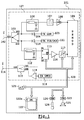
- FIG. 1 shows an apparatus 101.
- the device 101 is a mobile phone 101.
- the phone 101 includes a device 127 for transmitting reception of signals radio.
- the telephone 101 has a first antenna 102.
- the antenna 102 is connected to a diplexer 103. In our example it is a three-port diplexer 3.
- a first di0 port is connected to the antenna 102.
- Port di0 is a first input to the device for transmitting and receiving telephone 101.
- the duplexer 103 has two other doors di1 and di2.
- the duplexer 103 receives signals modulated according to standards on its di0 port GSM, PCS or DCS. Each of these signals therefore has a carrier frequency defined.
- the signals are routed either to port di1, these are GSM signals, or to port di2 if these are PCS or DCS signals.
- the diplexer 103 receives on its port di1 of the signals modulated according to the GSM standard, and on its port di2 of signals modulated according to the PCS DCS standard. These signals are directed to the port di0 to be broadcast by antenna 102.
- diplexing rather than to duplex because the signals received by the di0 port and the signals received by the ports di1 and di2 do not circulate at the same time in the diblexer.
- a selector in place of the diplexer 103 which would select which is the active connection among the di0- di1 and di0-di2 connections. Indeed a multimode mobile phone does not work in multiple modes at the same time.
- the di1 port is connected on the one hand to the input of a chain of processing, on the other hand at the output of a signal production chain according to GSM standard.
- the di1 port is therefore connected to a diode 104.
- the diode 104 is on the other hand connected to circuits 105 for producing GSM standard signals.
- Diode 104 allows the signals produced by circuits 105 while avoiding that the signals coming from the port di1 and received via the antenna 102 disturbs the operation of the circuits 105.
- the diode 104 therefore protects the circuits 105 from the signals received by the device 101 via its antenna 102.
- the port di1 is also connected to elements 106 for impedance matching. The role of these elements 106 is identical to the role of diode 104.
- the elements 106 make it possible to prevent signals produced by the circuits 105 are considered by the reception chain as received signals via the antenna 102.
- the adaptation elements 106 are connected on the other hand to an input of a band selector filter 107.
- the output of filter 107 is connected to the input of a low noise amplifier 108.
- the exit of amplifier 108 is connected to the input of a demodulation circuit 109 the filter 107 makes it possible to select the frequency band which must be retained before amplification, this band is a GSM band therefore aux around 900 MHz.
- Amplifier 108 is one of those commonly used in telephony according to the GSM standard. The design of the 108 amplifier is therefore under control, all the more easily since he only works at frequencies corresponding to the GSM standard, i.e. in a band narrow.
- the width of the selected band depends on the standard according to which phone 101 is working. This is valid for all standards. Standards define the width of a band that can be allocated for establishing communication, this is also called allocating a communication channel.
- Amplifier 108 amplifies the signals received by the antenna 102 which are often very very weak because attenuated during their propagation between the base station which sent them and the telephone 101 which receives them.
- the circuits 109 receive modulated signals and produce signals corresponding numbers after demodulation.
- the di2 port is connected to the output of a diode 110.
- the input of the diode 110 is connected to circuits 111 for producing signals according to the PCS or DCS standard.
- the role of the diode 110 is to prevent signals received by antenna 102 and exiting through port di2 disturb the functioning of circuits 111.
- Port di2 is also connected to elements 112 for impedance matching.
- the role of elements 112 is prevent the signals produced by circuits 111 from disturbing the operation of components located on the other side of components 112. In other words, the elements 112 protects the second reception chain signals produced by the circuits 111.
- the elements 106 and 112 may be band rejection filters whose frequency of rejection is variable depending on the carrier frequency of the signals produced respectively by circuits 105 and 111.
- Elements 112 are on the other hand connected to a port S1 of a selector 113.
- the selector 113 can establish a link between several of its ports.
- the selector 113 has three ports.
- the selectors 113 can establish a link between its ports S0 and S1, or between its ports S0 and S2.
- FIG. 1 shows that phone 101 has a second antenna 114.
- This second antenna 114 receives, or broadcasts, signals according to the UMTS standard.
- the antenna 114 is connected to a duplexer 115.
- the duplexer 115 has three ports.
- the antenna is connected to a port du0 duplexer 115.
- port du0 is a second device input transmitting and receiving telephone 101.
- Signals received on port du0 are directed to a port du1 of duplexer 115.
- the duplexer 115 receives signals which are routed to port du0.
- a duplexer can be realized by two adapted lines, each one to a frequency, connected by one of their ends. This end by which are connected the two lines is connected to the antenna 114.
- Port du1 of duplexer 115 is connected to port S2 of connector 113.
- Port S0 of selector 113 is connected to an input of an amplifier 116.
- the output of amplifier 116 is connected to the input of a filter 117.
- the output of the filter 117 is connected to the demodulation circuit 109.
- the reception chain, consisting of amplifier 116 and filter 117, therefore processes signals according to standards PCS, DCS and UMTS.
- the amplifier 116 therefore has a bandwidth which ranges from 1800 MHtz to 2.1 GHtz.
- the filter selection frequency 117 can be set to select only one frequency band corresponding to a reception channel in one of the PCS, DCS or UMTS.
- the port du2 of the selector 116 is connected to the output of a chain of production of signals according to the UMTS standard.
- This production line includes circuits 118 for producing signals, and an amplifier 119 of power whose output is connected to port du2. Signals produced by circuits 118 must be amplified in order to be broadcast by the antenna and to be correctly received by the base station to which the phone 101.
- Figure 1 shows that the phone 101 has a bus 120 for controlling in particular the selector 113, the filter 117 and the circuits 109.
- the bus 120 also makes it possible to control the circuits 105, 111 and 118.
- the connection of these circuits to bus 120 has not been drawn so as not to overload the drawing.
- circuits 105, 109, 111 and 118 have been represented by several blocks.
- it can be a single component capable of handling modulation and demodulation of the different standards managed by the 101 phone. In this case it is a component having several inputs and several outputs.
- bus is a set of wires or tracks comprising these elements in sufficient number to convey the control signals, addresses, data, interrupts, clocks and power.
- Figure 1 shows that phone 101 has a microprocessor 121, and a memory 122.
- the memory 122 comprises several zones, in particular an area 122a comprising instruction codes which control the microprocessor especially when it has to configure the transmission device reception of the telephone 101.
- microprocessor 121 controlled by codes instruction from zone 122a, command the selector 113 so that it establish a connection between ports S0 and S1.
- the microprocessor 121 also controls the filter 117 so that it selects the frequency carrier corresponding to that allocated to telephone 101 when it has connected to a base station. This frequency has been communicated on the phone 101 during a negotiation sequence that took place when the phone 101 is put into service, or during an appointment between the telephone 101 and a base station. This sequence of negotiation, or this time appointment, are well known to the standard GSM.
- the phone 101 is set to GSM mode, signals are received via the antenna 102 demodulated thanks to the circuit 109 which produces digital signals which are then read by the microprocessor 121 controlled by the instruction codes contained in another zone of the memory 122.
- the microprocessor 121 then processes and transfers these signals digital processed to a digital to analog converter 123.
- the Y123 converter is connected to a 125 speaker.
- the signals that are passed to converter 123 are transformed into analog signals which are acoustically transmitted by the loudspeaker 125.
- the user speaks into a microphone 126 thus producing analog signals which will be transmitted to an analog converter digital 124 which will produce corresponding digital signals.
- the elements 121 to 123 are connected to bus 120.
- the microprocessor 121 reads then the digital signals produced by converter 124 and provide these samples to circuit 105 which can then produce GSM signals corresponding. These GSM signals produced will then be broadcast by the antenna 102.
- the antenna 102 makes it possible to receive signals according to GSM, PCS and DCS standards, while antenna 114 can receive signals according to UMTS standards.
- the microprocessor 121 controls the selector 113 so that it establishes a link between ports S0 and S1.
- Microprocessor 121 controls also the filter 117 so that it selects the frequency band either in the PCS band or in the DCS band. This frequency band is known following a sequence of negotiations determined by PCS or DCS standard.
- Circuit 109 is then able to produce demodulated digital signals from analog signals received via antenna 102. These digital signals can then be broadcast via speaker 125.
- circuit 111 will be able to produce UMTS standard signals based on voice signals that have been picked up via the microphone 126.
- the operation of circuits 123 and 124 is identical regardless of how the phone 101 works.
- the microprocessor 121 controls the selector 113 so that it establishes a connection between ports S0 and S2.
- the microprocessor 121 also controls the filter 117 so to select the corresponding frequency band in the UMTS standard. These frequency bands for the UMTS standard are around 2.1 GHtz.
- the signals received by the telephone 101 are therefore via the antenna 114 and processed by the amplifier 116 and the filter 117.
- the signals transmitted by the telephone 101 are therefore broadcast by antenna 114 produced by circuits 118 and amplified by amplifier 119.
- the circuit 113 is produced either using transistors which are biased at the reverse of each other so that only one of them is passing at a time given, either using diodes which are also inversely polarized, one of the other so that only one of them is passable. If we make the selector 113 using transistors, just order them by their grids with a same control signal knowing that one of these control signals is reversed with respect to the other. This inversion is obtained for example by a NOT door. So the two transistors are never on at the same time time and only one of the connections S0-S1 or S0-S2 is established at the moment given.
- the first antenna 102 has a bandwidth of 880 MHz to 1990 MHz corresponding to standards GSM, DCS and PCS.
- the second antenna 114 has a bandwidth of 1900 MHz to 2170 MHz corresponding to UMTS standards.
- the first antenna 102 makes it possible to manage signals according to GSM, PCS, DCS, and UMTS TDD standards (division channel time) in reception.
- GSM Global System for Mobile Communications
- PCS Personal Communications Service
- DCS DCS
- UMTS TDD Universal Mobile Communications
- the second antenna 114 allows to manage signals according to UMTS FDD standards (division frequency) and UMTS TDD in transmission. This is because the signals issued in the UMTS TDD standard are close to those issued in the standard UMTS FDD.
- the microprocessor 121 therefore controls the selector 113 by depending on the nature of the signals.
- the difference with the first mode of operation is that the UMTS TDD signals received are processed with the selector 113 establishing a connection between its ports s1 and s0.
- the first antenna 102 has a bandwidth of 880 MHz to 2025 MHz corresponding to standards GSM, DCS, PCS and UMTS TDD.
- the second antenna 114 has a band bandwidth from 1900 MHz to 2170 MHz corresponding to UMTS standards.
- Figure 2 shows a variant of the invention. For figure 2 the elements identical to those of FIG. 1 are repeated with the same references.
- Figure 2 shows that phone 101 has an antenna 201 connected to a first port p0 of a selector 202.
- the selector 202 allows to establish a connection either between port p0 and a port p1 of the selector 202, or between port p0 and a port p2 of the selector 202.
- Port p1 is on the other hand connected to the di0 input of the device 127 for sending and receiving the phone 101.
- Port p2 is also connected to port du0 on the device 127.
- the selector 202 is also connected to the bus 120 which allows the microprocessor 121 to control the selector 120 and thus to direct the signals received by the antenna 201 according to the operating mode of the phone 101.
- the selector 202 establishes a connection between ports p0 and p1 when the telephone 101 operates according to one of the GSM, DCS, or PCS standards.
- the selector 202 establishes a connection between ports p0 and p2 when the phone 101 operates according to one of the UMTS standards.
- the selector 202 In a second operating mode, the selector 202 established a link between ports p0 and p1 when the telephone 101 operates according to one of the GSM, DCS, PCS, or UMTS TDD standards for reception. The selector 202 establishes a connection between ports p0 and p2 when the telephone 101 operates according to one of the UMTS FDD or UMTS TDD standards in emission.
Landscapes
- Engineering & Computer Science (AREA)
- Computer Networks & Wireless Communication (AREA)
- Signal Processing (AREA)
- Transceivers (AREA)
Abstract
Description
- plusieurs entrée, chacune correspondant à certaines normes,
- une première chaíne de réception pour traiter des signaux reçus, via une première entrée, dans une gamme de fréquences correspondant à des signaux selon des premières normes,
- une deuxième chaíne de réception pour traiter des signaux reçus, via la première et une deuxième entré, dans une gamme de fréquences correspondant à des signaux selon des deuxièmes normes,
- un sélecteur pour sélectionner, parmi des signaux reçus par les première et deuxième entrées, les signaux traités par la deuxième chaíne de réception.
Claims (12)
- Appareil (101) comportant un dispositif (102-119) d'émission réception de signaux radioélectriques fonctionnant selon plusieurs normes caractérisé en ce que le dispositif d'émission réception comporteplusieurs entrée (DI0, DU0), chacune correspondant à certaines normes,une première chaíne (107, 108) de réception pour traiter des signaux reçus, via une première entrée (DI0), dans une gamme de fréquences correspondant à des signaux selon des premières normes,une deuxième chaíne (116, 117) de réception pour traiter des signaux reçus, via la première et une deuxième entrée (DU0), dans une gamme de fréquences correspondant à des signaux selon des deuxièmes normes,un sélecteur (113) pour sélectionner, parmi des signaux reçus par les première et deuxième entrées, les signaux traités par la deuxième chaíne de réception.
- Appareil selon la revendication 1, caractérisé en ce que la première chaíne réception comporte un amplificateur (108) faible bruit.
- Appareil selon l'une des revendications 1 ou 2, caractérisé en ce que la deuxième chaíne de réception comporte un filtre (117) sélecteur de bande à fréquence de sélection variable.
- Appareil selon l'une des revendications 1 à 3, caractérisé en ce que la première chaíne traite des signaux selon la norme GSM, la deuxième chaíne traite des signaux selon les normes PCS, DCS et UMTS.
- Appareil selon la revendication 4, caractérisé en ce que la deuxième chaíne comporte un sélecteur (113) pour sélectionner parmi les signaux DCS PCS, et le signaux UMTS ceux qui sont traités.
- Appareil selon l'une de revendications 1 à 5, caractérisé en ce que le dispositif d'émission réception comporte :une première entrée sous forme d'un port DI0 d'un diplexeur (103) ayant deux autres ports DI1, et DI2 connecté au port DI0,une première chaíne de réception GSM dont l'entrée est connectée au port DI1 du diplexeur,une première sortie d'une chaíne de production de signaux GSM connectée sur le port DI1 du diplexeur,une deuxième chaíne de réception DCS PCS dont l'entrée est connectée au port DI2 du diplexeur,une deuxième sortie d'une chaíne de production de signaux DCS PCS connectée sur le port DI2 du diplexeur,une deuxième entrée sous forme d'un port DU0 d'un duplexeur (115) ayant deux autres ports DU1 et DU2 connecté au port DU0une connexion entre le port DU1 du duplexeur et la deuxième chaíne de réception,une troisième sortie d'une chaíne de production de signaux UMTS connectée sur le port DU2 du duplexeur.
- Appareil selon la revendication 6, caractérisé en ce que la deuxième chaíne de réception comporte en série une adaptation (112) d'impédance, un sélecteur (113), un amplificateur (116) et un filtre (117) sélecteur à fréquence de sélection variable, le sélecteur ayant trois, un port S0 connecté à l'adaptation, un port S1 connecté à une entrée de l'amplificateur, un port S2 connecté au port DU1 du duplexeur, le sélecteur permet d'établir une connexion soit entre S0 et S1, soit entre S0 et S2.
- Appareil selon l'une des revendications 1 à 7, caractérisé en ce que des chaíne de réception sont protégées, de préférence en adaptant leur impédance, pour que leur fonctionnement ne soit pas perturbé par des signaux produits par l'appareil.
- Appareil selon l'une des revendications 1 à 8, caractérisé en ce que des chaíne de production de signaux sont protégées, de préférence par des diodes, pour que leur fonctionnement ne soit pas perturbé par des signaux reçus par l'appareil via une antenne.
- Appareil selon l'une des revendications 1 à 9, caractérisé en ce que chaque entrée du dispositif d'émission réception est connecté à une antenne.
- Appareil selon l'une des revendications 1 à 9, caractérisé en ce que deux entrées du dispositif d'émission réception sont connectées à une seule antenne via un sélecteur.
- Appareil selon l'une des revendications 1 à 11, caractérisé en ce que l'appareil est un téléphone mobile.
Applications Claiming Priority (2)
| Application Number | Priority Date | Filing Date | Title |
|---|---|---|---|
| FR0011673A FR2814031B1 (fr) | 2000-09-13 | 2000-09-13 | Appareil communiquant multimodes comportant un dispositif d'emission reception a plusieurs entrees |
| FR0011673 | 2000-09-13 |
Publications (2)
| Publication Number | Publication Date |
|---|---|
| EP1189356A1 true EP1189356A1 (fr) | 2002-03-20 |
| EP1189356B1 EP1189356B1 (fr) | 2003-07-02 |
Family
ID=8854255
Family Applications (1)
| Application Number | Title | Priority Date | Filing Date |
|---|---|---|---|
| EP20010000421 Expired - Lifetime EP1189356B1 (fr) | 2000-09-13 | 2001-09-05 | Appareil communiquant multimode comportant un dispositif d'émission réception à plusieurs entrées |
Country Status (4)
| Country | Link |
|---|---|
| EP (1) | EP1189356B1 (fr) |
| DE (1) | DE60100421T2 (fr) |
| ES (1) | ES2202227T3 (fr) |
| FR (1) | FR2814031B1 (fr) |
Cited By (1)
| Publication number | Priority date | Publication date | Assignee | Title |
|---|---|---|---|---|
| WO2005034375A1 (fr) * | 2003-10-02 | 2005-04-14 | Benq Mobile Gmbh & Co. Ohg | Architecture de telephonie mobile multimode/multicanal |
Families Citing this family (3)
| Publication number | Priority date | Publication date | Assignee | Title |
|---|---|---|---|---|
| DE102004026133A1 (de) | 2004-05-28 | 2005-12-29 | Infineon Technologies Ag | Sendeanordnung, Empfangsanordnung, Transceiver sowie Verfahren zum Betreiben einer Sendeanordnung |
| DE102014102699B4 (de) * | 2014-02-28 | 2018-03-01 | Snaptrack, Inc. | Front-end Schaltung |
| DE102014102701B3 (de) | 2014-02-28 | 2015-08-27 | Epcos Ag | Frontendschaltung mit einem abstimmbaren Filter |
Citations (3)
| Publication number | Priority date | Publication date | Assignee | Title |
|---|---|---|---|---|
| WO1994011819A1 (fr) * | 1992-11-10 | 1994-05-26 | Motorola Inc. | Unite de communication radio a double mode |
| GB2312108A (en) * | 1996-04-08 | 1997-10-15 | Matsushita Electric Industrial Co Ltd | Multiband receiver with grouping of signals with the same modulation type into the same IF |
| GB2343592A (en) * | 1998-09-11 | 2000-05-10 | Nec Corp | Dual mode phone with one-frame-two slot communication |
-
2000
- 2000-09-13 FR FR0011673A patent/FR2814031B1/fr not_active Expired - Lifetime
-
2001
- 2001-09-05 ES ES01000421T patent/ES2202227T3/es not_active Expired - Lifetime
- 2001-09-05 EP EP20010000421 patent/EP1189356B1/fr not_active Expired - Lifetime
- 2001-09-05 DE DE2001600421 patent/DE60100421T2/de not_active Expired - Lifetime
Patent Citations (3)
| Publication number | Priority date | Publication date | Assignee | Title |
|---|---|---|---|---|
| WO1994011819A1 (fr) * | 1992-11-10 | 1994-05-26 | Motorola Inc. | Unite de communication radio a double mode |
| GB2312108A (en) * | 1996-04-08 | 1997-10-15 | Matsushita Electric Industrial Co Ltd | Multiband receiver with grouping of signals with the same modulation type into the same IF |
| GB2343592A (en) * | 1998-09-11 | 2000-05-10 | Nec Corp | Dual mode phone with one-frame-two slot communication |
Cited By (1)
| Publication number | Priority date | Publication date | Assignee | Title |
|---|---|---|---|---|
| WO2005034375A1 (fr) * | 2003-10-02 | 2005-04-14 | Benq Mobile Gmbh & Co. Ohg | Architecture de telephonie mobile multimode/multicanal |
Also Published As
| Publication number | Publication date |
|---|---|
| EP1189356B1 (fr) | 2003-07-02 |
| FR2814031B1 (fr) | 2002-11-08 |
| ES2202227T3 (es) | 2004-04-01 |
| FR2814031A1 (fr) | 2002-03-15 |
| DE60100421D1 (de) | 2003-08-07 |
| DE60100421T2 (de) | 2004-04-15 |
Similar Documents
| Publication | Publication Date | Title |
|---|---|---|
| EP0631400B1 (fr) | Dispositif d'émission/réception de signaux numériques portable bimode | |
| US20210091806A1 (en) | Methods of detecting power of individual carrier of aggregated carrier | |
| US6584304B1 (en) | Switchable wide band receiver front end for a multiband receiver | |
| KR0158785B1 (ko) | 무선통신장치 | |
| US20090286569A1 (en) | Apparatus method and computer program for interference reduction | |
| US20120189040A1 (en) | Multi-mode receiver | |
| EP2074700B1 (fr) | Module d'emission et de reception radioelectrique, adapte notamment aux radiocommunications large bande | |
| KR20130010104A (ko) | 상이한 주파수 대역들에서의 무선 주파수 송신들을 동시에 수신하기 위한 무선 회로 | |
| FR2793976A1 (fr) | Emetteur/recepteur a circuits d'interfaces internes bidirectionnels | |
| FR2682838A1 (fr) | Recepteur et emetteur radio produisant une diversite. | |
| FR2777407A1 (fr) | Signal de radiotelephonie cellulaire a canal supplementaire affecte au sens descendant, procede, systeme, mobile et station de base correspondant | |
| FR2949631A1 (fr) | Dispositif emission reception large bande permettant l'emission et la reception de signaux d'un canal selectionne dans une bande passante etendue dynamiquement | |
| US8611820B2 (en) | Signal separation for energy harvesting | |
| FR2916588A1 (fr) | Melangeur bidirectionnel de frequences, systeme emetteur/ recepteur radiofrequences comportant au moins un tel melangeur. | |
| EP1189356B1 (fr) | Appareil communiquant multimode comportant un dispositif d'émission réception à plusieurs entrées | |
| JPH10290176A (ja) | アンテナ共用装置 | |
| JP3105768B2 (ja) | 受信回路 | |
| EP0963053A2 (fr) | Procedé et circuit de filtre bidirectionel pour un émetteur-récepteur à bande latérale unique | |
| KR19990017779A (ko) | 통신단말기의 음성필터링장치 | |
| EP1499028A1 (fr) | Dispositif de communication mobile | |
| EP1191702B1 (fr) | Emetteur récepteur UMTS bimode | |
| EP1187355A1 (fr) | Appareil multimodes comportant un dispositif d'émission réception de signaux minimisant les moyens nécessaires pour gérer les différents modes | |
| JPS6039931A (ja) | トランシ−バ | |
| EP3092719B1 (fr) | Dispositif de filtrage pour terminal mobile portable pmr, terminal mobile | |
| JP2006262314A (ja) | 無線装置及びこれを備える無線通信端末装置 |
Legal Events
| Date | Code | Title | Description |
|---|---|---|---|
| PUAI | Public reference made under article 153(3) epc to a published international application that has entered the european phase |
Free format text: ORIGINAL CODE: 0009012 |
|
| AK | Designated contracting states |
Kind code of ref document: A1 Designated state(s): AT BE CH CY DE DK ES FI FR GB GR IE IT LI LU MC NL PT SE TR Kind code of ref document: A1 Designated state(s): DE ES GB IT |
|
| AX | Request for extension of the european patent |
Free format text: AL;LT;LV;MK;RO;SI |
|
| 17P | Request for examination filed |
Effective date: 20020214 |
|
| 17Q | First examination report despatched |
Effective date: 20020515 |
|
| AKX | Designation fees paid |
Free format text: DE ES GB IT |
|
| GRAH | Despatch of communication of intention to grant a patent |
Free format text: ORIGINAL CODE: EPIDOS IGRA |
|
| GRAH | Despatch of communication of intention to grant a patent |
Free format text: ORIGINAL CODE: EPIDOS IGRA |
|
| GRAA | (expected) grant |
Free format text: ORIGINAL CODE: 0009210 |
|
| AK | Designated contracting states |
Designated state(s): DE ES GB IT |
|
| REG | Reference to a national code |
Ref country code: GB Ref legal event code: FG4D Free format text: NOT ENGLISH |
|
| REG | Reference to a national code |
Ref country code: IE Ref legal event code: FG4D Free format text: FRENCH |
|
| REF | Corresponds to: |
Ref document number: 60100421 Country of ref document: DE Date of ref document: 20030807 Kind code of ref document: P |
|
| GBT | Gb: translation of ep patent filed (gb section 77(6)(a)/1977) | ||
| REG | Reference to a national code |
Ref country code: IE Ref legal event code: FD4D |
|
| REG | Reference to a national code |
Ref country code: ES Ref legal event code: FG2A Ref document number: 2202227 Country of ref document: ES Kind code of ref document: T3 |
|
| PLBE | No opposition filed within time limit |
Free format text: ORIGINAL CODE: 0009261 |
|
| STAA | Information on the status of an ep patent application or granted ep patent |
Free format text: STATUS: NO OPPOSITION FILED WITHIN TIME LIMIT |
|
| 26N | No opposition filed |
Effective date: 20040405 |
|
| REG | Reference to a national code |
Ref country code: DE Ref legal event code: R082 Ref document number: 60100421 Country of ref document: DE Representative=s name: PATENT- UND RECHTSANWAELTE BARDEHLE PAGENBERG, DE |
|
| REG | Reference to a national code |
Ref country code: DE Ref legal event code: R082 Ref document number: 60100421 Country of ref document: DE Representative=s name: BARDEHLE PAGENBERG PARTNERSCHAFT MBB PATENTANW, DE Effective date: 20111026 Ref country code: DE Ref legal event code: R081 Ref document number: 60100421 Country of ref document: DE Owner name: APPLE INC., CUPERTINO, US Free format text: FORMER OWNER: SAGEM MOBILES, PARIS, FR Effective date: 20111026 |
|
| REG | Reference to a national code |
Ref country code: GB Ref legal event code: 732E Free format text: REGISTERED BETWEEN 20120426 AND 20120502 |
|
| REG | Reference to a national code |
Ref country code: GB Ref legal event code: 732E Free format text: REGISTERED BETWEEN 20120503 AND 20120509 |
|
| PGFP | Annual fee paid to national office [announced via postgrant information from national office to epo] |
Ref country code: GB Payment date: 20200826 Year of fee payment: 20 Ref country code: DE Payment date: 20200826 Year of fee payment: 20 |
|
| PGFP | Annual fee paid to national office [announced via postgrant information from national office to epo] |
Ref country code: IT Payment date: 20200812 Year of fee payment: 20 |
|
| PGFP | Annual fee paid to national office [announced via postgrant information from national office to epo] |
Ref country code: ES Payment date: 20201005 Year of fee payment: 20 |
|
| REG | Reference to a national code |
Ref country code: DE Ref legal event code: R071 Ref document number: 60100421 Country of ref document: DE |
|
| REG | Reference to a national code |
Ref country code: GB Ref legal event code: PE20 Expiry date: 20210904 |
|
| PG25 | Lapsed in a contracting state [announced via postgrant information from national office to epo] |
Ref country code: GB Free format text: LAPSE BECAUSE OF EXPIRATION OF PROTECTION Effective date: 20210904 |
|
| REG | Reference to a national code |
Ref country code: ES Ref legal event code: FD2A Effective date: 20211227 |
|
| PG25 | Lapsed in a contracting state [announced via postgrant information from national office to epo] |
Ref country code: ES Free format text: LAPSE BECAUSE OF EXPIRATION OF PROTECTION Effective date: 20210906 |