EP1189497A2 - Apparat und Verfahren zur Montage von Bauelementen auf einem Substrat - Google Patents
Apparat und Verfahren zur Montage von Bauelementen auf einem Substrat Download PDFInfo
- Publication number
- EP1189497A2 EP1189497A2 EP01122267A EP01122267A EP1189497A2 EP 1189497 A2 EP1189497 A2 EP 1189497A2 EP 01122267 A EP01122267 A EP 01122267A EP 01122267 A EP01122267 A EP 01122267A EP 1189497 A2 EP1189497 A2 EP 1189497A2
- Authority
- EP
- European Patent Office
- Prior art keywords
- component
- substrate
- holder
- mounting
- nozzle
- Prior art date
- Legal status (The legal status is an assumption and is not a legal conclusion. Google has not performed a legal analysis and makes no representation as to the accuracy of the status listed.)
- Ceased
Links
Images


Classifications
-
- H—ELECTRICITY
- H05—ELECTRIC TECHNIQUES NOT OTHERWISE PROVIDED FOR
- H05K—PRINTED CIRCUITS; CASINGS OR CONSTRUCTIONAL DETAILS OF ELECTRIC APPARATUS; MANUFACTURE OF ASSEMBLAGES OF ELECTRICAL COMPONENTS
- H05K13/00—Apparatus or processes specially adapted for manufacturing or adjusting assemblages of electric components
- H05K13/08—Monitoring manufacture of assemblages
- H05K13/085—Production planning, e.g. of allocation of products to machines, of mounting sequences at machine or facility level
- H05K13/0853—Determination of transport trajectories inside mounting machines
-
- H—ELECTRICITY
- H05—ELECTRIC TECHNIQUES NOT OTHERWISE PROVIDED FOR
- H05K—PRINTED CIRCUITS; CASINGS OR CONSTRUCTIONAL DETAILS OF ELECTRIC APPARATUS; MANUFACTURE OF ASSEMBLAGES OF ELECTRICAL COMPONENTS
- H05K13/00—Apparatus or processes specially adapted for manufacturing or adjusting assemblages of electric components
- H05K13/04—Mounting of components, e.g. of leadless components
- H05K13/0404—Pick-and-place heads or apparatus, e.g. with jaws
- H05K13/0413—Pick-and-place heads or apparatus, e.g. with jaws with orientation of the component while holding it; Drive mechanisms for gripping tools, e.g. lifting, lowering or turning of gripping tools
-
- Y—GENERAL TAGGING OF NEW TECHNOLOGICAL DEVELOPMENTS; GENERAL TAGGING OF CROSS-SECTIONAL TECHNOLOGIES SPANNING OVER SEVERAL SECTIONS OF THE IPC; TECHNICAL SUBJECTS COVERED BY FORMER USPC CROSS-REFERENCE ART COLLECTIONS [XRACs] AND DIGESTS
- Y10—TECHNICAL SUBJECTS COVERED BY FORMER USPC
- Y10T—TECHNICAL SUBJECTS COVERED BY FORMER US CLASSIFICATION
- Y10T29/00—Metal working
- Y10T29/49—Method of mechanical manufacture
- Y10T29/49002—Electrical device making
- Y10T29/49117—Conductor or circuit manufacturing
- Y10T29/49124—On flat or curved insulated base, e.g., printed circuit, etc.
- Y10T29/4913—Assembling to base an electrical component, e.g., capacitor, etc.
- Y10T29/49131—Assembling to base an electrical component, e.g., capacitor, etc. by utilizing optical sighting device
-
- Y—GENERAL TAGGING OF NEW TECHNOLOGICAL DEVELOPMENTS; GENERAL TAGGING OF CROSS-SECTIONAL TECHNOLOGIES SPANNING OVER SEVERAL SECTIONS OF THE IPC; TECHNICAL SUBJECTS COVERED BY FORMER USPC CROSS-REFERENCE ART COLLECTIONS [XRACs] AND DIGESTS
- Y10—TECHNICAL SUBJECTS COVERED BY FORMER USPC
- Y10T—TECHNICAL SUBJECTS COVERED BY FORMER US CLASSIFICATION
- Y10T29/00—Metal working
- Y10T29/49—Method of mechanical manufacture
- Y10T29/49002—Electrical device making
- Y10T29/49117—Conductor or circuit manufacturing
- Y10T29/49124—On flat or curved insulated base, e.g., printed circuit, etc.
- Y10T29/4913—Assembling to base an electrical component, e.g., capacitor, etc.
- Y10T29/49133—Assembling to base an electrical component, e.g., capacitor, etc. with component orienting
-
- Y—GENERAL TAGGING OF NEW TECHNOLOGICAL DEVELOPMENTS; GENERAL TAGGING OF CROSS-SECTIONAL TECHNOLOGIES SPANNING OVER SEVERAL SECTIONS OF THE IPC; TECHNICAL SUBJECTS COVERED BY FORMER USPC CROSS-REFERENCE ART COLLECTIONS [XRACs] AND DIGESTS
- Y10—TECHNICAL SUBJECTS COVERED BY FORMER USPC
- Y10T—TECHNICAL SUBJECTS COVERED BY FORMER US CLASSIFICATION
- Y10T29/00—Metal working
- Y10T29/49—Method of mechanical manufacture
- Y10T29/49002—Electrical device making
- Y10T29/49117—Conductor or circuit manufacturing
- Y10T29/49124—On flat or curved insulated base, e.g., printed circuit, etc.
- Y10T29/4913—Assembling to base an electrical component, e.g., capacitor, etc.
- Y10T29/49144—Assembling to base an electrical component, e.g., capacitor, etc. by metal fusion
-
- Y—GENERAL TAGGING OF NEW TECHNOLOGICAL DEVELOPMENTS; GENERAL TAGGING OF CROSS-SECTIONAL TECHNOLOGIES SPANNING OVER SEVERAL SECTIONS OF THE IPC; TECHNICAL SUBJECTS COVERED BY FORMER USPC CROSS-REFERENCE ART COLLECTIONS [XRACs] AND DIGESTS
- Y10—TECHNICAL SUBJECTS COVERED BY FORMER USPC
- Y10T—TECHNICAL SUBJECTS COVERED BY FORMER US CLASSIFICATION
- Y10T29/00—Metal working
- Y10T29/53—Means to assemble or disassemble
- Y10T29/53087—Means to assemble or disassemble with signal, scale, illuminator, or optical viewer
-
- Y—GENERAL TAGGING OF NEW TECHNOLOGICAL DEVELOPMENTS; GENERAL TAGGING OF CROSS-SECTIONAL TECHNOLOGIES SPANNING OVER SEVERAL SECTIONS OF THE IPC; TECHNICAL SUBJECTS COVERED BY FORMER USPC CROSS-REFERENCE ART COLLECTIONS [XRACs] AND DIGESTS
- Y10—TECHNICAL SUBJECTS COVERED BY FORMER USPC
- Y10T—TECHNICAL SUBJECTS COVERED BY FORMER US CLASSIFICATION
- Y10T29/00—Metal working
- Y10T29/53—Means to assemble or disassemble
- Y10T29/5313—Means to assemble electrical device
- Y10T29/53174—Means to fasten electrical component to wiring board, base, or substrate
- Y10T29/53178—Chip component
-
- Y—GENERAL TAGGING OF NEW TECHNOLOGICAL DEVELOPMENTS; GENERAL TAGGING OF CROSS-SECTIONAL TECHNOLOGIES SPANNING OVER SEVERAL SECTIONS OF THE IPC; TECHNICAL SUBJECTS COVERED BY FORMER USPC CROSS-REFERENCE ART COLLECTIONS [XRACs] AND DIGESTS
- Y10—TECHNICAL SUBJECTS COVERED BY FORMER USPC
- Y10T—TECHNICAL SUBJECTS COVERED BY FORMER US CLASSIFICATION
- Y10T29/00—Metal working
- Y10T29/53—Means to assemble or disassemble
- Y10T29/5313—Means to assemble electrical device
- Y10T29/53174—Means to fasten electrical component to wiring board, base, or substrate
- Y10T29/53183—Multilead component
-
- Y—GENERAL TAGGING OF NEW TECHNOLOGICAL DEVELOPMENTS; GENERAL TAGGING OF CROSS-SECTIONAL TECHNOLOGIES SPANNING OVER SEVERAL SECTIONS OF THE IPC; TECHNICAL SUBJECTS COVERED BY FORMER USPC CROSS-REFERENCE ART COLLECTIONS [XRACs] AND DIGESTS
- Y10—TECHNICAL SUBJECTS COVERED BY FORMER USPC
- Y10T—TECHNICAL SUBJECTS COVERED BY FORMER US CLASSIFICATION
- Y10T29/00—Metal working
- Y10T29/53—Means to assemble or disassemble
- Y10T29/5313—Means to assemble electrical device
- Y10T29/53196—Means to apply magnetic force directly to position or hold work part
Definitions
- the present invention relates to an apparatus and method for mounting electric components on a substrate such as circuit board.
- the system 1 includes a supply section 2 for supplying electric components to the system 1, a placement head 3 for receiving the component from the supply section 2 and then mounting the component on a substrate such as circuit board, a transport unit 4 for transporting the placement head 3, a recognition device 5 for taking a digital image of the component held by the placement head 3, a holding section 6 for receiving and holding the substrate onto which the components are mounted, and a controller 7 for controlling an entire operation of the system 1.
- the placement head 3 moves to a predetermined position above the supply section 2 bearing a component supply cassette 11, for example, with a number of components 12.
- a vertically extending vacuum nozzle 13 in the form of quill supported by the placement head 3 is moved down to receive the component 12.
- the placement head 3 is then rotated about a vertical axis, i.e. Z-axis, by an angle controller 14 so that the component is oriented in a predetermined direction.
- the recognition device 5 takes an image of the component 12 supported by the nozzle 13 of the placement head 13 moving past a predetermined position opposing the image processor 5.
- the image is transmitted to an image processor 20 where the image is processed according to a specific image processing technique to determine a position of the component, i.e., its horizontal and/or angular displacement relative to the nozzle.
- Information indicating the position of the component is transmitted to the controller 7. Based upon the information, the controller 7 corrects the position of the component. Then, the nozzle 13 is moved above a predetermined placement position of the substrate 18 and then down toward the substrate 18 so that the component 12 is mounted on the substrate.
- Fig. 32 is a flowchart showing a conventional method for mounting components.
- the nozzle 13 receives the component 12.
- the recognition device 5 takes a picture of the component 12 held by the nozzle 13.
- the picture is processed at the image processor 20.
- the position of the component 12 is determined at step S1103 whether the component 12 can be mounted on the substrate. If the component 12 is incapable of being mounted on the substrate, the nozzle 13 brings the component to a collect station (not shown) at step S1106. Otherwise, the horizontal and/or angular displacement of the nozzle 13 is determined at step S1104. Using the displacement, the horizontal position of the placement head 3 and/or the angular orientation of the nozzle 13 is adjusted.
- the component 12 is mounted in position onto the substrate 18 at step S1105. In this process, no judgement is made whether the nozzle 13 interferes with one or more components mounted on the substrate 18.
- the electric devices are likely to be small sized and light-weighted, increasing a density of components mounted on the substrate 18 considerably.
- a clearance between neighboring components of about 1.0mm x 0.5mm is decreased to about 0.2mm.
- each component should be mounted on the substrate as it does not interfere with another component mounted on the substrate.
- a displacement of the component 12 relative to the nozzle 13 may result in an interference between the nozzle 13 and the component 12 mounted on the substrate 18.
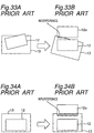
- Figs. 33A to 34B illustrated are nozzle 13 and components 12, both viewed from the substrate.
- the controller 7 uses the image of the component captured by the recognition device 5 and the result obtained by the image processor 20, the controller 7 corrects the horizontal and/or angular position of the component 12 relative to the nozzle 13 before the mounting of the component 12 so that the component is placed on a predetermined, correct position on the substrate.
- Fig. 34A shows the nozzle and the component retained by the nozzle in which the component is horizontally offset from a center of the nozzle.
- the nozzle 13 is displaced so that the component is mounted on a correct position on the substrate and this in turn results in an interference with another component 12a mounted on the substrate as shown by hatching.
- the interference may be more problematic for the case with a reduced clearance when considering a deviation of height and/or inclination of the component. That is, the interference between the nozzle 13 and the component 12a results in another displacement of the component 12a. What is worse, the component 12 may be damaged, which results in a deterioration and/or malfunction of the circuit.
- a purpose of the present invention is to provide an apparatus and method for mounting component on a substrate, which is capable of mounting component on the substrate without any interference between the nozzle and the component mounted on the substrate even when only a small clearance is ensured between the components on the substrate due to a requirement of compactness of the component.
- a holder receives a component from a component supply and then places the component on a substrate.
- a judgement is made whether the holder makes an interference with another component mounted on the substrate. Then, if the judgement is affirmative, an mounting of the component held by the holder is prohibited. If, on the other hand, the judgement is negative, the component held by the holder is mounted on the substrate.
- the system of the present invention has an appearance that is substantially identical to the conventional system illustrated in Fig. 31.
- the system 1 has a component supply 2, a placement head 3 for receiving and mounting, a robot or transport device 4 for transporting the placement head 3, a recognition device 5 for taking a picture of the component held by the placement head, a holder 6 for receiving and then holding the substrate, and a controller 7 for controlling an entire operation of the system.
- the placement head 3 causes its nozzle 13 to receive the component 12 from the component supply 2 and, while moving toward the recognition device 5, rotate the nozzle about its vertical axis so that the component orients in a predetermined mounting direction.
- the recognition device 5 takes a picture of the component held by nozzle 13 of the placement head 3.
- the picture is then processed by the image processor 20 to determine the position of the component 12 on the nozzle 13.
- the determined position is transmitted to the controller 7.
- the placement head 3 Based upon an instruction from the controller 7, the placement head 3 corrects, if any, horizontal and/or angular displacement of the component and then places the component in a predetermined area on the substrate 18.
- the picture of the component is taken while the placement head 3 is moving toward the placement station.
- the placement head 3 may halt while taking the picture of the component.
- Fig. 1 is a flowchart showing a process for mounting a component according to an embodiment of the present invention, which is carried by the controller 7.
- the component 12 is received by nozzle 13 of the placement head.
- the recognition device 5 picks up an image of the component held by nozzle.
- the image is transmitted to and then processed by the image processor 20.
- step S3 If it is determined at step S3 that component is in the condition that it can be mounted on the substrate, the program proceeds to step S4. At this step, another determination is made whether, during the mounting of the component, the nozzle 13 makes an interference with the component mounted on substrate due to the horizontal and/or angular adjustment of the component relative to the nozzle. This determination will be described fully together with the specific embodiments. If, on the other hand, it is determined at step S4 that there exists a possibility of the interference between the nozzle 13 and the component 12a mounted on the substrate, the program proceeds to step S7. At this step, the component 12 held by the nozzle 13 is discarded at the collect station not shown.
- the program proceeds to step S5 where a horizontal and/or angular correction of the nozzle 13 required for the mounting of the component 12 is determined. Subsequently, the nozzle 13 is corrected and then the component 12 is mounted on the substrate 18 at step S6. After the completion of the mounting or the discard of the component, the nozzle 13 moves again toward the component supply 2 for the next pickup operation of the component. The above steps are repeated for the subsequent components to be mounted on the substrate.
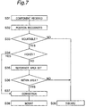
- step S11 a position of the component 12 held by the nozzle is determined at step S12, which is used for another determination at step S13 whether the component can be mounted on the substrate. If it is determined at step S13 that the component is unable to be mounted on the substrate in a proper way, the program proceeds to step S19 where the component is discarded at the collect station.
- the operations described above are the same as those described for the first embodiment.
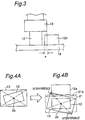
- step 13 If, on the other hand, it is determined at step 13 that the component is held so that it can be mounted on the substrate, another determination is made at step S14. At this step, it is determined whether the nozzle 13 makes an interference with the component 12a mounted on the substrate at the placement of the component 12 held by the nozzle 13. For this purpose, a first decision is made whether a height of the component 12 held by the nozzle 13 is greater than that of the component 12a around which the component 12 will be mounted.
- Fig. 3 illustrates a spatial relationship between the component 12 held by the nozzle and the component 12a mounted on the substrate.
- step S17 a horizontal and/or angular correction of the nozzle is determined in order to mount the component 12 in a predetermined position on the substrate. Based upon this determination, the component 12 is placed on the substrate 18 at step S18.
- the height of the component 12 is less than that of the mounted component 12a, a calculation is made to determine a relationship between the nozzle 13 and the mounted component 12a, i.e., whether the nozzle 13 makes an interference with the mounted component 12a.
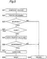
- Figs. 4A and 4B schematically illustrate a spatial relationship between the nozzle 13 and the component 12 held by the nozzle in which it is assumed that the component 12 is improperly inclined to the nozzle.
- the nozzle 13 is turned around to direct the component in a proper direction, which in turn can result in an interference between the nozzle 13 and the mounted component 12a.
- a new concept or reference area (safety region) 21 is used for determining whether the nozzle interferes with the mounted component.
- the reference area 21 is predetermined in light of the position of the neighboring, mounted component 12a.
- an outer periphery of the mounted component 12a defines a part of an outline of the reference area 21.
- the reference area may be spaced away from the outer periphery of the mounted component, leaving a certain clearance therebetween for safe.
- An amount of horizontal and/or angular correction of the component relative to the nozzle in Fig. 4A is calculated in light of a known configuration and reference position of the nozzle. Also, the actual displacement of the component is determined by comparing the image of the component taken by the recognition device and the known configuration and reference position of the nozzle.
- the reference position of the nozzle 13, which is supposed with its center located at the center 25 of the nozzle 13 as shown in Fig. 4A, is stored in the controller 7 or the imaging device 20. Also, in order to suppose the reference area 21, also used are a shape, size and position of the component 12a mounted on the substrate, stored in the controller 7.
- step S16 determines whether the nozzle 13 stays within the reference area 21. When even a small part of the nozzle 13 positions outside the reference area, it is determined that the nozzle 13 interferes with the mounted component 12a. Then, at step S19 the component 12 is discarded from the nozzle 13 without being mounted on the substrate. If, on the other hand, the nozzle 13 stays fully within the reference area 21, it is determined that no interference occurs between the nozzle and the mounted component 12a. Then, the program proceeds to step S17 where the horizontal and/angular displacement or the amount of correction of the component 12 is calculated. Based upon this calculation, the displacement of the component 12 is removed by moving the nozzle 13.
- step S18 the component 12 is placed on the substrate at step S18.
- the nozzle moves back to the supply section 2 for the next pickup operation of the component.
- the program returns to step S11 so that the above-described procedures are performed again.
- a clearance between the reference area 21 and the outline of the mounted component may vary from one direction to the other direction depending upon the features of the neighboring components. Also, the reference area 21 may be extended in one direction in the form of strip if no neighboring component exists in that direction and, therefore, there is no necessity for considering the possible interference in that direction.
- the controller performs only steps S13 to S15 for every component without making any determination at step S14. This also applies to the following embodiments.
- step S21 the component 12 is received on the nozzle. Then, a position of the component 12 held by the nozzle is recognized at step S22, which is used for another determination at step S23 whether the component can be mounted on the substrate. If it is determined at step S23 that the component is unable to be mounted on the substrate in a proper way, the program proceeds to step S29 where the component is discarded at the collect station.
- step S21 the component 12 is received on the nozzle.
- step S22 a position of the component 12 held by the nozzle is recognized at step S22, which is used for another determination at step S23 whether the component can be mounted on the substrate. If it is determined at step S23 that the component is unable to be mounted on the substrate in a proper way, the program proceeds to step S29 where the component is discarded at the collect station.
- step S24 it is determined whether a height of the component 12 held by the nozzle 13 is greater than that of the component 12a around which the component 12 will be mounted. If the height of the component 12 to be mounted is equal to or more than that of the mounted component 12a, the program proceeds to step S27 where a horizontal and/or angular correction of the nozzle is calculated. Based upon this calculation, the component 12 is placed on the substrate 18 at step S28.
- step S25 a position of the nozzle 13 above the substrate 18 at the mounting of the component 12 is calculated. For example, if the component 12 is inclined to the substrate 18 as shown in Fig. 6A, calculated are possible positions of the nozzle 13 on the substrate 18 in which the component 12 is oriented in the proper direction as shown in Fig. 6B.
- step S26 determines whether the nozzle 13 overlaps at least in part the component 12a which is supposed to have been mounted in a predetermined position on the substrate 18. If the overlap is established, it is determined that the nozzle 13 interferes with the mounted component 12a. In this instance, the component 12 is transported to the discard station at step S29 without being mounted on the substrate. Otherwise, the program proceeds to step S27 where an amount of horizontal and/or angular correction of the placement head 3 is calculated. Based upon this calculation, a necessary horizontal and/or angular correction is made to the placement head 3. Then, the component 12 is mounted on the substrate 18. After the mount or discard of the component 12, the nozzle 13 is returned to the supply section 2 for the pickup operation of the subsequent component and, then, the program proceeds again to step S21.
- the interference is determined using the position in which the neighboring component 12a is supposed to have been mounted on the substrate.
- information of not only the shape and size of the nozzle 13 but also the shape and size and the mounted position of the component 12a are stored in the controller 7. Using this information, the controller 7 calculates the positions occupied by the nozzle 13 and the component 12a.
- step S31 the component 12 is received on the nozzle. Then, a position of the component 12 held by the nozzle is recognized at step S32, which is used for another determination at step S33 whether the component can be mounted on the substrate. If it is determined at step S33 that the component is unable to be mounted on the substrate in a proper way, the program proceeds to step S39 where the component is discarded at the collect station.
- step S31 the component 12 is received on the nozzle.
- step S32 a position of the component 12 held by the nozzle is recognized at step S32, which is used for another determination at step S33 whether the component can be mounted on the substrate. If it is determined at step S33 that the component is unable to be mounted on the substrate in a proper way, the program proceeds to step S39 where the component is discarded at the collect station.
- step S34 it is determined whether a height of the component 12 held by the nozzle 13 is greater than that of the component 12a around which the component 12 will be mounted. If the height of the component 12 to be mounted is equal to or more than that of the mounted component 12a, the program proceeds to step S37 where an amount of horizontal and/or angular correction of the placement head 3 is calculated. Based upon this calculation, the component 12 is placed on the substrate 18 at step S38.
- step S35 If, on the other hand, the height of the component 12 is less than that of the mounted component 12a, the program proceeds to step S35 where, as shown in Fig. 8B, irrespective of the size of the mounted component 12a, an reference area 21a is determined from the size of the component 12 in an image processing so that it is greater than the size of the component 12 by a certain length.
- a size of the expanded area of the reference area can be determined arbitrarily. The size of the reference area may be determined using a predetermined limit distance from the neighboring component, stored in the controller as shown in Fig. 21.
- step 36 it is determined at step 36 whether the nozzle 13 stays within the reference area 21a in light of size and shape of the nozzle 13, the reference position of the nozzle 13 (e.g., its center 25), and the position of the component 12 relative to the nozzle 13 determined at step S32. If not, the program proceeds to step S39 where the component 12 is discarded at the collect station. Otherwise, the program proceeds to step S37 where an amount of horizontal and/or angular correction of the placement head 3 is calculated. Based upon this calculation, a horizontal and/or angular correction is made to the placement head 3. Then, the component 12 is mounted on the substrate 18 at step S38. After the mount or discard of the component 12, the nozzle 13 is returned to the supply section 2 for the pickup operation of the subsequent component and, then, the program proceeds again to step S31.
- the size of the reference area 21a may be varied from one direction to the other direction according to the arrangement of the components on the substrate, in particular, neighboring component or components. Also, the reference area 21a may be extended in a certain direction in the form of strip if no neighboring component exists in that direction and, therefore, there is no necessity for considering the possible interference in that direction. Further, if there is a possible interference only in one direction, as shown in Fig. 8C the reference area may be defined only in that direction.
- the amount of horizontal and/or angular displacement of the component 12 relative to the nozzle 13 is determined by comparing the known shape and size and the preset reference holding position of the nozzle 13 (e.g., the center of the nozzle 13) with the image picked up by the recognition device 5.
- the preset reference holding position of the nozzle 13 e.g., the center of the nozzle 13
- they may be determined from the image picked up by the recognition device 5 and then used for the position determination. This also ensures a precise determination whether there is a possible interference between the nozzle 13 and the mounted component 12a.
- whether the nozzle 13 interferes with the mounted component 12a is determined by the image processor 20, it may be performed by the controller 7.
- the placement head 4 is transported in a horizontal plane by the robot 4, a rotary mounting device having a plurality of placement heads arranged on a circle and rotating successively for mounting may be used instead.
- the system has another imaging device for picking up an image of the substrate 18 in order to establish the position of the component 12a mounted on the substrate and thereby to determine a possible interference between the nozzle 13 and the mounted component 12a.
- a possible interference between the nozzle 13 and the mounted component 12a For example, as shown in Fig. 9A, in the previous embodiment it is determined whether the nozzle 13 of which horizontal and/or angular position has been adjusted falls at least in part in the reference area 22 defined by the position of the mounted component 12a. However, a certain condition may be thought that as shown in Fig. 9B the component 12a is mounted on the substrate in an inclined fashion with respect to a predetermined direction and position.
- a component mounting apparatus 30 has a second image processor 31 for recognition of the component 12a mounted on the substrate 18.
- the image processor 31 is positioned on the placement head 3 near the nozzle 13.
- Other structures of the system 30 are similar to or identical to those described in the previous embodiment, so that no description is made thereto.
- FIG. 11 there is shown a flowchart indicating a component mounting process performed by the controller 7.
- the flowchart is similar to that described with respect to the second embodiment, except that the image processor 31 recognizes the position of the component 12a mounted on the substrate 18 at step S41.
- the recognition is carried out after the placement head 3 has reached a position where it places the component 12 on the substrate 18, preferably after the completion of the placement of the component 12.
- the image of the mounted component 12a is transmitted to the image processor 20 or the controller 7 where it is used at step S47 to define the reference area.
- a deformed reference area 22a may be defined for the inclined component 12a.
- the deformed reference area 22a ensures to prevent the interference between the nozzle 13 and the component 12a placed improperly. Also ensured is a proper mounting of the component 12 which would be prohibited from being mounted when supposing a non-deformed reference area as shown in Figs. 9A to 9C.
- the image processor 31 may be provided on another moving member rather than the placement head 3. In this instance, the image processor 31 with the moving member may oppose the substrate 18 for the recognition of the substrate 18 while the placement head 3 is away from substrate 18.
- the component 12 which is discarded due to the possible interference between the nozzle and the mounted component is allowed to be mounted on the substrate 18 by adjusting the horizontal and/or angular position of the nozzle while preventing the interference of the nozzle and the mounted component. That is, in the second embodiment, as shown in Fig. 4B if the nozzle 13 protrudes beyond the reference area 21, the component 12 is discarded without being mounted on the substrate 18. However, as shown in Figs. 11A and 11B, even in the same condition the nozzle 13 rotates in a direction indicated by arrow 27 so that it stays wholly within the reference area 21, allowing the component 12 to be mounted on the substrate 18. This not only prevents the interference between the nozzle and the component on the substrate but also increases an efficiency of the mounting.
- the nozzle 13 is rotated into the reference area, it may be transported linearly in a direction away from the component 12a on the substrate 18. Also, the rotational movement may be combined with the liner movement.
- the above adjustment of the nozzle 13 can cause the component 12 to incline as indicated by the solid line, relative to the proper position on the substrate indicated by the long and short dotted line 12b. This may increase a likelihood of the interference between the component 12 mounted on the substrate and the nozzle 13 in the placement movement for the subsequent component. However, the interference is prevented by reducing a size of the reference area 21 according to the inclination in the formation of the region for the subsequent component. The nozzle 13 is discarded unless the nozzle 13 enters entirely within the reference area.
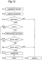
- Fig. 13 is a flowchart showing the component mounting method of this embodiment.
- processes performed at steps S11 to S19 are the same as that described with regard to the second embodiment of the present invention. If it is determined at step S16 that the nozzle 16 is outside the reference area, another determination is made at step S61 whether the nozzle would be entirely entered within the reference area by the liner and/or rotational movement of the nozzle. If the result is affirmative, the position of the nozzle is adjusted at step S17 so that the nozzle entirely stays within the region. Then, the component held by the nozzle is mounted on the substrate at step S18. Otherwise, the component 12 is discarded at the collect station.
- data of interference between the nozzle 13 and the component 12a on the substrate 18 is collected in the process of mountings for one or more certain number of substrates. Then, the collected data is used for the protection of the interference in the subsequent mountings. For example, in mountings for the predetermined number of substrates, interference data including the number, the degree, and position of interference caused between the nozzle and the component is memorized. The data is processed statistically, for example, to obtain a tendency of interference or inclination. This tendency shows, for example, when and/or where the interference is likely to occur. Therefore, if that tendency is confirmed at step S72, an adjustment is made to cancel or reduce the tendency, preventing the interference between the nozzle 13 and the component 12a on the substrate 18.
- the adjustment may be made by the rotation and/or horizontal movement of component 12 to be mounted and/or 12a mounted on the substrate. If, by the adjustment, the former tendency is eliminated but another tendency is appeared in the predetermined number of subsequent mountings, a further adjustment is made to cancel or reduce the latter tendency. In this instance, the adjustment may be made to either of two components 12 and 12a alternatively or both. When adjusting both components, the amount of adjustment may be divided substantially equally for two components.
- the interference determination using the reference area 21 is performed to the rotary type component mounting apparatus.
- the component mounting apparatus 100 generally includes a component supply section 110 for supplying electronic components successively, a rotary head 112 for receiving and then mounting the components on a substrate 18, and an X-Y table 114 for positioning the substrate 18.
- the substrate 18 is supplied from a substrate supply section 116 and then positioned on the X-Y table 114.
- the rotary head 112 receives the components 12 from the component supply section 110.
- a position of each component on the rotary head 112 is corrected, if necessary.
- the corrected component is then mounted on the substrate 18.
- the substrate is transported from the X-Y table to a substrate discharge station 118.
- the system 100 has an input section 120 for the data input, a display station 122 for the data display, and a controller 107 for controlling operations of the devices in the system.
- the input data includes sizes of the components and control data and the display data includes data showing the condition of the devices in the system.
- the component supply section 110 has a set of parallel parts cassettes 11 each holding a number of electronic components 12.
- the set of parts cassettes is supported so that it can move back ard forth in a direction perpendicular to the drawing, which ensures each of the parts cassettes to provide its component for a component supply region 110a.
- the X-Y table 114 is supported so that it moves between the substrate supply section 116 and the substrate discharge section 118. At the substrate supply section 116, the table 114 reaches a position communicated with a substrate inlet where it receives the substrate on which the components will be mounted. Then, the table 114 holds and then transports the substrate 18 into a placement position where the components are mounted thereon by the rotary head 112.
- the table 114 moves left to right and back and forth so that each component is mounted on a predetermined, corresponding position on the substrate. After the completion of the mountings of the components, the table 114 moves to a position adjacent to the substrate discharge section 118 for the discharge of the substrate to the substrate discharge station 118.
- the rotary head 112 has 12 placement heads at regular intervals on its periphery.
- Each of the placement heads 126 has five nozzles 132 for holding components of different sizes and is supported so that it moves up and down and rotates about a central, vertical axis thereof. This allows that, when catching and mounting the component, each nozzle 132 takes an outermost position on a circle indicated by long and short dotted line in Fig. 17.
- each placement head 126 is transported by the index rotation of the rotary frame 128 from component supply position 110a of the component supply section 110 to an opposite, component placement position and then back again to the component supply position 110a through various stations.
- the nozzle 132 faces the component supply position and receives the component 12 from component supply section 110. Then, the thickness of the component held by the nozzle 132 is measured at ST3 by a two-dimensional line sensor not shown, which is then transmitted to the system 100. The system 100 determines whether the thickness measured is less than a predetermined value. If the determination is affirmative, the system recognizes that no component is supported by the nozzle or the component is incorrectly supported by the nozzle.
- a two-dimensional CCD camera i.e., displacement detector
- a horizontal and/or angular displacement of the component is determined, which is then transmitted to the system 100.
- the nozzle rotates about its vertical axis according to the determined, horizontal and/or angular displacement to orient the component in a proper direction.
- the X-Y table is positioned. Then, the placement head 126 moves down to place the component onto the substrate 18 in position. If it has been determined at ST 3 or ST4 that the component is incorrectly supported on the nozzle or the wrong component is supported on the nozzle, the component is discarded from the nozzle at respective stations.
- the placement head 126 is rotated about its vertical axis depending upon the component to be mounted to place the corresponding nozzle 132 into the outermost position 134.
- the angular displacement may be corrected by the rotation of the placement head. This results in a further horizontal displacement of the component, which is eliminated by the movement of the X-Y table.
- This method is featured in that a determination is made whether the nozzle or the component supported on the nozzle makes an interference with the component mounted on the substrate, by the use of various criterions.
- the controller 107 has an NC data store section 141 for storing data defining amounting position of each component on the substrate; an arrangement data store section 142 for storing data of the supply position of each component defined in the NC data and the types of components; a component data store section 143 for storing data defining features such as the shape of each component and the type of each nozzle; a nozzle size data store section 144 for storing data defining the size of each nozzle; a calculator 145 for calculating each distance between two neighboring components on the substrate in both, X and Y directions using data provided from the stores 141, 142, and 143; a distance data store section 146 for storing the calculated distances by the calculator 145; and an interference judge 148 for judging the existence of the interference using data from the data store section 146 and also determining a suitable clearance for each component and mounting position.
- the system 100 includes NC program, arrangement program, and component library, for example, stored therein.
- the NC program defines an order of components to be mounted and has supply positions (Z-number) and placement positions (X- and Y-coordinates) of the components. As can be seen from the drawing, one line of such data is prepared for each component.
- the arrangement program 152 defines data that includes the shape of component for each Z-number by the use of associated code in order to distinguish the type of component to be supplied.
- the component library 153 defines data of component shape code, component feature code, operational condition, supply condition, and neighboring condition.
- the component shape code defines the type of component.
- the component feature code defines the size of the component.
- the supply condition defines how and by what the component is supplied.
- the neighboring condition defines the size of the nozzle and the clearance between the neighboring components on the substrate in order to determine the interference between the nozzle or component to be mounted and the component mounted.
- the interference can be determined using a constant, limit distance defined for the prevention of the interference.
- the limit distance is automatically determined by taking the neighboring condition into account for each mounting of component, rather than using the constant, limit distance.
- the NC program 151, arrangement program 152, and component library 153 are established and stored prior to the actual mounting of the components. Then, a program for mounting is generated by the combination of the NC program 151 corresponding to the substrate on which the components are mounted and the arrangement program 152 defining the component supply positions and the shapes of the components designated in the NC library 153 with the component shape codes.
- Fig. 22 shows a flowchart for calculating a distance between two neighboring components mounted on the substrate and made at a distance calculator 145.
- Sill NC data store section 141 provides a mounting, horizontal and angular position (x and y coordinates and ⁇ ) of the component on the substrate.
- the arrangement data store section 143 provides the shape code of the component.
- the component data store section 143 provides dimensions in the x and y directions of the component corresponding to the shape code.
- the distance calculator 145 calculates an area (x s , y s ) on the substrate to be occupied by the component at step S114.
- the area (x s , y s ) is stored a distance data store section 146.
- the area (x s , y s ) is defined by the following equations: wherein, as shown in Fig. 23,
- Fig. 24 This calculation is performed for every component to be mounted on the substrate at step S115. Then, the area of one component P is provided from the distance data store section 146. Next, another component leaving a minimum distance from the component in either direction is determined. This process is illustrated in Fig. 24 in which, for one component P, selected in x-direction is the component Pl that leaves a minimum distance ⁇ x from the component P and selected in y-direction is another component Pu that leaves a minimum distance ⁇ y from the component P. For example, as shown in Fig.
- the calculated distance ⁇ x and ⁇ y are
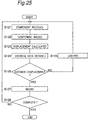
- Fig. 25 there is shown a flowchart of the procedure for the determination of the possible interference of the component, performed before the mounting of the components 12.
- this program according to the preset mount program, among a number of parts cassettes prepared at the component supply 110 one parts cassette 11 bearing a desired component 3 designated by the mount program is moved to the component supply position 110a.
- the component 12 is received by the nozzle 132 of the placement head 126 positioned at the component supply section ST1 of the rotary head 110a at step S121.
- the rotary head 112 is subject to the index rotation to transport the placement head 126 with the component into the recognition station ST4 where the component is recognized by the two-dimensional CCD camera at step S122.
- the image recognized by the recognition device is used to determine the relative relationship between the nozzle 132 and the component 12 in the x and y directions at step S123. That is, at this step, it is determined the offsets of the nozzle 132 from the component 12 in the x- and y-directions. Each offset bears a plus or minus sign.
- the neighboring distance information for the component supported by the nozzle is retrieved from the distance data store section 146 at step S124.
- step S125 another determination is made at step S125 whether the offset of the nozzle 132 from the component, calculated at step S123, is less than the neighboring distance retrieved in either direction. If the offset is greater than the neighboring distance, there exists a possible interference between the nozzle or the component supported on the nozzle and another component mounted on the substrate. Therefore, at step S126 the placement head 126 is moved to the discard station ST6 where the component is released from the nozzle into a collect container not shown. The same component is then picked up again by the nozzle and, if there is no possible interference, mounted on the position of the substrate where the discarded component was intended to be mounted. If, on the other hand, the offset is less than the neighboring distance, the component is mounted at step S127 on a predetermined position of the substrate. If it is determined that the above steps are performed for every component, the program is completed at step S128.
- data is automatically generated for determining the interference between the nozzle or component supported on the nozzle and another component mounted on the substrate for the nozzle and each component.
- conventional data can also be used in this method without any necessity of modification. This means that no complicated operation is needed for the input of new data for the mounting.
- the interference is checked for each component independently, which prevents the unwanted discard of the component capable of being mounted. This ensures an effective mounting of the components. Further, immediately after the discard of one component, the same component is mounted on the substrate without moving the rotary head, which ensures to reduce a total time of the mounting.
- Discussions will be made to another system and process for mounting of the component according to the tenth embodiment of the present invention.
- data of the components mounted on the substrate are used for the determination of the interference.
- the system 100 further includes a memory section 147 for holding a list of positions of the components mounted on the substrate, which list being dynamically updated after the mounting of each component.
- a nozzle interference check section 148 determines for each component supported on the nozzle whether it will make an interference with any component mounted on the substrate using data from the memory sections 144, 146 and 147. In each determination, a suitable neighboring limit distance is calculated for each component and its position.
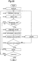
- a flowchart indicating procedures carried out at the memory section 147 in Fig. 18 during mounting For example, when a new substrate is introduced into the system 100, the memory section 147 clears the list of positions of the components mounted in the mountings for the previous substrate at step S131. After a new component is supported on the nozzle at step S132, it is determined at step S133 whether another components neighboring the new component on the substrate has been mounted on the substrate. If the neighboring component has already been mounted on the substrate, the interference check is made only for that neighboring direction according to the procedures described in the ninth embodiment at steps that follow step S134. Otherwise, no interference check is made and the component supported by the nozzle is mounted on the substrate at step S139.
- the interference check is eliminated. This means that minimum checks are carried out, shortening a time for mounting of each component.
- the system may simply be de-energized and then make a warning to an operator of this system. This allows the operator to determine whether the component supported on the nozzle should be discarded.
- the ninth and tenth embodiments have been described in combination with the system 100 having the rotary head 12, they are equally applied to the system 1 in which the placement head moves back and forth on the substrate fixed in the system shown in Fig. 31 and another system shown in Figs. 27 and 30 in which the placement head has a plurality of nozzles for supporting plural components simultaneously (see Fig. 29).
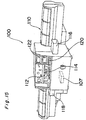
- the devices equipped in the system in Fig. 27 are operationally connected to each other as shown in Fig. 28.
- the system 200 has a guide portion including a pair of guide rails 252 each extending from a substrate supply section 216 through a substrate support section 217 to a substrate discharge section 218 each located at the center of a base frame 250. This allows that the substrate 18 introduced at the supply section 216 is transported to the support section 217 where the components are mounted thereon and then discharge from the discharge section 218.
- a base frame 250 arranged above the substrate 18 is provided on its opposite sides with y-axis robots 260 and 262 which in turn support an X-axis robot 264 so that by the driving of the y-axis robots 260 and 262 the x-axis robot moves back and forth in the x-direction.
- Each robot has a transport mechanism.
- the transport mechanism has a nut secured to a movable member and a threaded shaft secured to a fixed member and drivingly connected to a motor so that, by the driving of the motor, the shaft rotates to transport the movable member back and forth alternately.
- the placement head 266 supported by the X-Y transport mechanism with the x-axis robot 264 and y-axis robots 260 and 262 supports a component by its nozzle 232 for its placement onto a predetermined position of the substrate.
- the component may be a circuit chip such as resistor and condenser supplied from a parts cassette, for example, and another large electronic device such as IC connector (e.g., SOP and QFP) supplied from a parts tray, for example.
- the mounting procedures are controlled by the controller 207 in Fig. 28 according to a program memorized and preset in the memory 1001.
- the program may be inputted by manually using keys prepared at an operation panel, for example.
- the parts cassettes 11 are arranged on opposite sides of the paired guide rails 252, e.g., on the right upper and left lower sides. Each parts cassette 11 has a strip-like component holder wound about a reel and holding a number of components or circuit chips such as resistors and condensers.
- the parts tray 268, can support a pair of two trays 268a extending perpendicular to the guide rails, respectively. Each tray 268a slides toward the guide rails 252 according to the number of components to be supplied so that the component supply portion stays at a predetermined pickup position with respect to the y-direction. Typically, the tray 268a supports a number of electronic components such as QFP.
- a image processor 220 is provided near the substrate positioned by the pair of guide rails 252 in order to detect a two dimensional displacement or the position of the component supported by the nozzle 232 and also to cancel the displacement by the movement of the head 266.
- the image processor has a recognition device at its bottom and a housing surrounding around the recognition device.
- a number of light emitters such as light emitting diodes are provided stepwise inside the housing for the illumination of the component supported on the nozzle. This allows that light is emitted from various directions toward a mounting surface of the component, which ensures to pick up a clear image of the component with a suitable angle irrespective of the type of the component.
- the angle is predetermined for each component according to the preset component recognition data.
- the image picked up by the image processor 220 is processed by the controller to determine the center of the component and positions of the electrodes to be used for the correction of the placement position and/or angle.
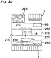
- the transport head 266 has a component holder or a multiple head with a plurality of placement heads (e.g., first to fourth placement heads 226a to 226d of the same structure).
- Each placement head has a nozzle 232, an actuator 278 for moving the nozzle 272 up and down, and a pulley 284.
- the pulleys 284 of the first and third placement heads 226a and 226c are drivingly connected through a timing belt 282 to a ⁇ -rotation motor 280a so that the nozzles 232 of the heads can rotate about respective vertical axes thereof simultaneously.
- the pulleys 284 of the second and fourth placement heads 226b and 226d are connected through another timing belt 282 to another ⁇ -rotation motor 280b so that the nozzles 232 of the heads can rotate about respective axes thereof simultaneously.
- Each actuator 278 is made of air-cylinder, for example, so that by turning on and off the air-cylinder the nozzle head 232 moves up and down for receiving and holding of the component.
- each of the placement heads 226a-226d is connected to an individual motor for its ⁇ -rotation.
- the number of motors is minimized.
- Each nozzle 232 of the placement head is replaceable and spare nozzles are accommodated in a nozzle stacker 286 mounted on the substrate 250 of the system 200.
- a various nozzles are used such as small size nozzle for the chips of about 1.0mm x 0.5mm and medium size nozzle for QFP of about 18mm x 18mm.
- the substrate 18 is introduced at the supply section 216 of the paired guide rails 252 and then transported into the holding section 217. Then, the placement head 266 is moved by the X-Y robot transversely or horizontally in the X-Y plane to receive the predetermined component from the parts cassette 11 or parts tray 268. The component is then passed by the recognition device of the image processor 220 to recognize the position of the component supported by the nozzle. Using the position of the component, the motor drives to rotate the nozzle 232 for the correction of the position of the component, if necessary. Then, the component is placed on the predetermined component mounting position on the substrate 18.
- Each of the placement heads 226a-226d moves down the nozzle 232 vertically, i.e., in the z-direction, by the driving of the actuator 278 when catching the component from the parts cassette 11 or the parts tray 268 and also when placing the component onto the substrate 18. Also, the nozzle is replaced depending upon the type of the component.
- the components are divided into several groups, i.e., high speed, medium speed, and low speed mounting components depending upon the weight and size thereof.
- a plurality of placement heads may be used for the simultaneous catching and/or mounting of the components.
- each distance of the neighboring components is calculated according to the program shown in Fig. 22 and then stored in the memory unit 146.
- the substrate 18 is transported from the supply section 216 into the holding section 217.
- the component is picked up from the parts cassette or pats tray 268 by the placement head 216 driven according to the mounting program.
- the interference is checked for the component supported on the nozzle according to the flowchart shown in Fig. 25.
- the recognition device takes a picture of the component supported on the nozzle. Using the image picked up by the recognition device, the position or the displacement of the component relative to the nozzle is determined.
- the component is mounted on the substrate.
- the interference check between the nozzle or component supported on the nozzle and the component mounted on the substrate is performed as described in the second embodiment.
- This embodiment is directed to a computer readable recording medium.
- a program having procedures for judging the interference between the nozzle 13, 132, and 232 and the mounted component 12a is recorded therein.
- the program has several steps of
- the recording medium is preferably used for the system described in connection with the second embodiment, for example. Also, the program recorded in the recording medium is installed and then carried out in the controller 7, 107, or 207.
- the horizontal and/or angular position of the nozzle and/or the component may be adjusted so as not to interfere with the component mounted on the substrate for the mounting of the component rather discarding the component as described in connection with the sixth embodiment.
- processes described in connection with other embodiments can also be memorized in respective recording mediums. In this case, each of the recording mediums is used for the installation of the program into the controller 7, 107, or 207.
- the present invention prevents the interference between the component holder or the component supported by the component holder and another component mounted on the substrate even though there remains a slight clearance between the components, producing a high quality substrate on which components have been mounted.
Landscapes
- Engineering & Computer Science (AREA)
- Manufacturing & Machinery (AREA)
- Microelectronics & Electronic Packaging (AREA)
- Operations Research (AREA)
- Supply And Installment Of Electrical Components (AREA)
Applications Claiming Priority (4)
| Application Number | Priority Date | Filing Date | Title |
|---|---|---|---|
| JP2000282440A JP4498570B2 (ja) | 2000-09-18 | 2000-09-18 | 電子部品実装方法及び電子部品実装装置 |
| JP2000282440 | 2000-09-18 | ||
| JP2000292148 | 2000-09-26 | ||
| JP2000292148 | 2000-09-26 |
Publications (2)
| Publication Number | Publication Date |
|---|---|
| EP1189497A2 true EP1189497A2 (de) | 2002-03-20 |
| EP1189497A3 EP1189497A3 (de) | 2003-07-02 |
Family
ID=26600152
Family Applications (1)
| Application Number | Title | Priority Date | Filing Date |
|---|---|---|---|
| EP01122267A Ceased EP1189497A3 (de) | 2000-09-18 | 2001-09-18 | Apparat und Verfahren zur Montage von Bauelementen auf einem Substrat |
Country Status (2)
| Country | Link |
|---|---|
| US (3) | US6718630B2 (de) |
| EP (1) | EP1189497A3 (de) |
Cited By (8)
| Publication number | Priority date | Publication date | Assignee | Title |
|---|---|---|---|---|
| EP1771060A1 (de) * | 2005-09-30 | 2007-04-04 | Hitachi High-Tech Instruments Co., Ltd. | Einrichtung zur Montage von elektronischen Bauteilen |
| EP1876879A3 (de) * | 2006-06-30 | 2008-07-02 | Siemens Aktiengesellschaft | Klassifizierung von aufgenommenen Bauelementen bei der Bestückung von Bauelementeträgern |
| DE102007046434A1 (de) | 2007-09-28 | 2008-12-04 | Siemens Ag | Verfahren zur Ermittlung einer optimalen Reihenfolge beim Bestücken von Substraten mit Bauelementen |
| CN105960834A (zh) * | 2014-03-31 | 2016-09-21 | 雅马哈发动机株式会社 | 电子元件安装装置 |
| EP3346813A4 (de) * | 2015-09-01 | 2018-08-22 | Fuji Machine Mfg. Co., Ltd. | Vorrichtung zur einstellung der erforderlichen präzision |
| CN110814717A (zh) * | 2019-11-20 | 2020-02-21 | 四川长虹电器股份有限公司 | 混线螺钉锁附方法 |
| US20200241498A1 (en) * | 2016-10-08 | 2020-07-30 | Capcon Limited | Apparatus, control method and control device of semiconductor packaging |
| EP3923693A4 (de) * | 2019-02-05 | 2022-02-16 | Fuji Corporation | Vorrichtung und verfahren zur einstellung zulässiger werte |
Families Citing this family (44)
| Publication number | Priority date | Publication date | Assignee | Title |
|---|---|---|---|---|
| SG142150A1 (en) * | 2000-07-16 | 2008-05-28 | Univ Texas | High-resolution overlay alignment systems for imprint lithography |
| KR100827741B1 (ko) | 2000-07-17 | 2008-05-07 | 보드 오브 리전츠, 더 유니버시티 오브 텍사스 시스템 | 임프린트 리소그래피 공정을 위한 자동 유체 분배 방법 및시스템 |
| JP2004505273A (ja) | 2000-08-01 | 2004-02-19 | ボード・オブ・リージエンツ,ザ・ユニバーシテイ・オブ・テキサス・システム | 転写リソグラフィのための透明テンプレートと基板の間のギャップおよび配向を高精度でセンシングするための方法 |
| JP4582963B2 (ja) * | 2001-06-14 | 2010-11-17 | パナソニック株式会社 | 電子部品装着装置 |
| US20050064344A1 (en) * | 2003-09-18 | 2005-03-24 | University Of Texas System Board Of Regents | Imprint lithography templates having alignment marks |
| JP2003060395A (ja) | 2001-08-10 | 2003-02-28 | Matsushita Electric Ind Co Ltd | 電子部品の実装方法および実装装置 |
| US6874225B2 (en) * | 2001-12-18 | 2005-04-05 | Matsushita Electric Industrial Co., Ltd. | Electronic component mounting apparatus |
| US7179079B2 (en) * | 2002-07-08 | 2007-02-20 | Molecular Imprints, Inc. | Conforming template for patterning liquids disposed on substrates |
| US7019819B2 (en) | 2002-11-13 | 2006-03-28 | Molecular Imprints, Inc. | Chucking system for modulating shapes of substrates |
| US7027156B2 (en) | 2002-08-01 | 2006-04-11 | Molecular Imprints, Inc. | Scatterometry alignment for imprint lithography |
| US7070405B2 (en) * | 2002-08-01 | 2006-07-04 | Molecular Imprints, Inc. | Alignment systems for imprint lithography |
| US8349241B2 (en) | 2002-10-04 | 2013-01-08 | Molecular Imprints, Inc. | Method to arrange features on a substrate to replicate features having minimal dimensional variability |
| US6929762B2 (en) | 2002-11-13 | 2005-08-16 | Molecular Imprints, Inc. | Method of reducing pattern distortions during imprint lithography processes |
| US7641840B2 (en) | 2002-11-13 | 2010-01-05 | Molecular Imprints, Inc. | Method for expelling gas positioned between a substrate and a mold |
| US6871558B2 (en) | 2002-12-12 | 2005-03-29 | Molecular Imprints, Inc. | Method for determining characteristics of substrate employing fluid geometries |
| US7122079B2 (en) | 2004-02-27 | 2006-10-17 | Molecular Imprints, Inc. | Composition for an etching mask comprising a silicon-containing material |
| US7136150B2 (en) | 2003-09-25 | 2006-11-14 | Molecular Imprints, Inc. | Imprint lithography template having opaque alignment marks |
| US7472472B2 (en) * | 2003-12-26 | 2009-01-06 | Panasonic Corporation | Electronic part mounting apparatus |
| US7906180B2 (en) | 2004-02-27 | 2011-03-15 | Molecular Imprints, Inc. | Composition for an etching mask comprising a silicon-containing material |
| US7533459B2 (en) * | 2004-04-27 | 2009-05-19 | Hitachi High-Tech Instruments, Co., Ltd. | Electronic component mounting method and electronic component mounting apparatus |
| CN101379435A (zh) * | 2004-06-03 | 2009-03-04 | 得克萨斯州大学系统董事会 | 用于改进显微蚀刻的对齐和覆盖的系统和方法 |
| US7768624B2 (en) * | 2004-06-03 | 2010-08-03 | Board Of Regents, The University Of Texas System | Method for obtaining force combinations for template deformation using nullspace and methods optimization techniques |
| US7785526B2 (en) | 2004-07-20 | 2010-08-31 | Molecular Imprints, Inc. | Imprint alignment method, system, and template |
| US7630067B2 (en) | 2004-11-30 | 2009-12-08 | Molecular Imprints, Inc. | Interferometric analysis method for the manufacture of nano-scale devices |
| US20070231421A1 (en) * | 2006-04-03 | 2007-10-04 | Molecular Imprints, Inc. | Enhanced Multi Channel Alignment |
| US7292326B2 (en) * | 2004-11-30 | 2007-11-06 | Molecular Imprints, Inc. | Interferometric analysis for the manufacture of nano-scale devices |
| JP4559243B2 (ja) * | 2005-01-28 | 2010-10-06 | 株式会社日立ハイテクインスツルメンツ | 電子部品の装着方法及び電子部品の装着装置 |
| US7636999B2 (en) * | 2005-01-31 | 2009-12-29 | Molecular Imprints, Inc. | Method of retaining a substrate to a wafer chuck |
| US20060177535A1 (en) * | 2005-02-04 | 2006-08-10 | Molecular Imprints, Inc. | Imprint lithography template to facilitate control of liquid movement |
| US7798801B2 (en) * | 2005-01-31 | 2010-09-21 | Molecular Imprints, Inc. | Chucking system for nano-manufacturing |
| US7635263B2 (en) * | 2005-01-31 | 2009-12-22 | Molecular Imprints, Inc. | Chucking system comprising an array of fluid chambers |
| US7670530B2 (en) | 2006-01-20 | 2010-03-02 | Molecular Imprints, Inc. | Patterning substrates employing multiple chucks |
| MY144847A (en) | 2005-12-08 | 2011-11-30 | Molecular Imprints Inc | Method and system for double-sided patterning of substrates |
| JP4692268B2 (ja) * | 2005-12-22 | 2011-06-01 | パナソニック株式会社 | 電子部品実装システムおよび電子部品実装方法 |
| US8215946B2 (en) | 2006-05-18 | 2012-07-10 | Molecular Imprints, Inc. | Imprint lithography system and method |
| DE102006024524A1 (de) * | 2006-05-23 | 2007-12-06 | Von Ardenne Anlagentechnik Gmbh | Infrarotstrahlung reflektierendes, transparentes Schichtsystem |
| JP5027468B2 (ja) * | 2006-09-15 | 2012-09-19 | 日本ミクロコーティング株式会社 | プローブクリーニング用又はプローブ加工用シート、及びプローブ加工方法 |
| US9008836B2 (en) * | 2007-01-09 | 2015-04-14 | Abb Inc. | Method and system for robotic assembly parameter optimization |
| JP2009124019A (ja) * | 2007-11-16 | 2009-06-04 | Fujitsu Ltd | 基板ユニットの製造方法及びマウンタ装置 |
| KR101613196B1 (ko) * | 2010-11-17 | 2016-04-19 | 한화테크윈 주식회사 | 플립칩 장착 방법 및 플립칩 장착기 |
| US9015928B2 (en) * | 2013-07-25 | 2015-04-28 | Panasonic Intellectual Property Management Co., Ltd. | Electronic component mounting apparatus |
| CN107926152B (zh) * | 2015-09-01 | 2020-04-07 | 株式会社富士 | 作业分配装置 |
| JP6906158B2 (ja) * | 2017-02-15 | 2021-07-21 | パナソニックIpマネジメント株式会社 | 部品搭載装置および部品搭載方法 |
| JP6942555B2 (ja) * | 2017-08-03 | 2021-09-29 | 東京エレクトロン株式会社 | 基板処理方法、コンピュータ記憶媒体及び基板処理システム |
Family Cites Families (13)
| Publication number | Priority date | Publication date | Assignee | Title |
|---|---|---|---|---|
| JPH0668696B2 (ja) * | 1985-02-22 | 1994-08-31 | 株式会社日立製作所 | 挿入機用ncデータ作成方法 |
| JPS62144392A (ja) * | 1985-12-19 | 1987-06-27 | ティーディーケイ株式会社 | 電子部品実装方法 |
| US5070589A (en) * | 1989-02-08 | 1991-12-10 | Westinghouse Electric Corp. | Process for servicing a jet pump hold down beam in a nuclear reactor |
| JPH02303200A (ja) | 1989-05-18 | 1990-12-17 | Hitachi Ltd | 電子部品装着装置 |
| US5377405A (en) * | 1992-07-01 | 1995-01-03 | Yamaha Hatsudoki Kabushiki Kaisha | Method for mounting components and an apparatus therefor |
| US5339248A (en) * | 1992-08-27 | 1994-08-16 | Matsushita Electric Industrial Co., Ltd. | Apparatus for mounting electronic component on substrate |
| JP3024457B2 (ja) * | 1993-09-30 | 2000-03-21 | 松下電器産業株式会社 | 電子部品実装装置および電子部品実装方法 |
| US5671527A (en) * | 1995-11-01 | 1997-09-30 | Fuji Machine Mfg. Co., Ltd. | Electronic-component mounting system |
| JPH10224099A (ja) * | 1997-02-04 | 1998-08-21 | Fuji Mach Mfg Co Ltd | 回路部品装着方法および回路部品装着システム |
| US6023680A (en) * | 1997-05-15 | 2000-02-08 | Panasonic Technologies, Inc. | Methods, apparatus and computer program products for automated visual inspection |
| US6230393B1 (en) | 1997-07-07 | 2001-05-15 | Matsushita Electric Industrial Co., Ltd. | Method and device for mounting electronic component |
| US6240633B1 (en) * | 1999-08-11 | 2001-06-05 | Motorola, Inc. | Automatic defect detection and generation of control code for subsequent defect repair on an assembly line |
| US6538425B1 (en) * | 1999-11-29 | 2003-03-25 | Fuji Machine Mfg. Co., Ltd. | Method of measuring accuracy of electric-component mounting system |
-
2001
- 2001-09-17 US US09/953,180 patent/US6718630B2/en not_active Expired - Fee Related
- 2001-09-18 EP EP01122267A patent/EP1189497A3/de not_active Ceased
-
2004
- 2004-01-23 US US10/762,452 patent/US7155817B2/en not_active Expired - Lifetime
- 2004-01-23 US US10/762,282 patent/US7299539B2/en not_active Expired - Fee Related
Cited By (15)
| Publication number | Priority date | Publication date | Assignee | Title |
|---|---|---|---|---|
| EP2268121A1 (de) * | 2005-09-30 | 2010-12-29 | Hitachi High-Tech Instruments Co., Ltd. | Einrichtung zur Montage von elektronischen Bauteilen |
| EP1771060A1 (de) * | 2005-09-30 | 2007-04-04 | Hitachi High-Tech Instruments Co., Ltd. | Einrichtung zur Montage von elektronischen Bauteilen |
| EP1876879A3 (de) * | 2006-06-30 | 2008-07-02 | Siemens Aktiengesellschaft | Klassifizierung von aufgenommenen Bauelementen bei der Bestückung von Bauelementeträgern |
| DE102007046434A1 (de) | 2007-09-28 | 2008-12-04 | Siemens Ag | Verfahren zur Ermittlung einer optimalen Reihenfolge beim Bestücken von Substraten mit Bauelementen |
| US10172268B2 (en) | 2014-03-31 | 2019-01-01 | Yamaha Hatsudoki Kabushiki Kaisha | Electronic component mounting device |
| CN105960834A (zh) * | 2014-03-31 | 2016-09-21 | 雅马哈发动机株式会社 | 电子元件安装装置 |
| EP3128825A4 (de) * | 2014-03-31 | 2017-05-31 | Yamaha Hatsudoki Kabushiki Kaisha | Montagesystem für elektronische komponenten |
| EP3346813A4 (de) * | 2015-09-01 | 2018-08-22 | Fuji Machine Mfg. Co., Ltd. | Vorrichtung zur einstellung der erforderlichen präzision |
| US10935963B2 (en) | 2015-09-01 | 2021-03-02 | Fuji Corporation | Required accuracy setting device |
| US20200241498A1 (en) * | 2016-10-08 | 2020-07-30 | Capcon Limited | Apparatus, control method and control device of semiconductor packaging |
| US11774935B2 (en) * | 2016-10-08 | 2023-10-03 | Capcon Limited | Apparatus, control method and control device of semiconductor packaging |
| EP3923693A4 (de) * | 2019-02-05 | 2022-02-16 | Fuji Corporation | Vorrichtung und verfahren zur einstellung zulässiger werte |
| US12075568B2 (en) | 2019-02-05 | 2024-08-27 | Fuji Corporation | Allowable value setting device and allowable value setting method |
| CN110814717A (zh) * | 2019-11-20 | 2020-02-21 | 四川长虹电器股份有限公司 | 混线螺钉锁附方法 |
| CN110814717B (zh) * | 2019-11-20 | 2021-08-06 | 四川长虹电器股份有限公司 | 混线螺钉锁附方法 |
Also Published As
| Publication number | Publication date |
|---|---|
| US20020069525A1 (en) | 2002-06-13 |
| US6718630B2 (en) | 2004-04-13 |
| EP1189497A3 (de) | 2003-07-02 |
| US7155817B2 (en) | 2007-01-02 |
| US20040148764A1 (en) | 2004-08-05 |
| US7299539B2 (en) | 2007-11-27 |
| US20040148768A1 (en) | 2004-08-05 |
Similar Documents
| Publication | Publication Date | Title |
|---|---|---|
| EP1189497A2 (de) | Apparat und Verfahren zur Montage von Bauelementen auf einem Substrat | |
| EP1553815B1 (de) | Einrichtung und vorrichtung zur montage von bauteilen | |
| US6729018B1 (en) | Apparatus for mounting components | |
| KR100332525B1 (ko) | 부품 장착 방법 및 부품 장착 장치 | |
| EP0708587B1 (de) | Verfahren und Vorrichtung zur Montage eines Teils auf einer spezifischen Position | |
| EP0660657B1 (de) | Verfahren und Montagevorrichtung zum Montieren eines Bauelementes auf eine spezifische Position | |
| JP2554437B2 (ja) | 部品装着方法及び同装置 | |
| EP0920243B1 (de) | Zuführungseinrichtung und bestückungsvorrichtung für elektronische bauteile | |
| EP1617717B1 (de) | Einrichtung und verfahren zum anbringen eines teils | |
| EP0416878B1 (de) | Vorrichtung für elektronische Bauteile und Verfahren für die Bestückung der elektronischen Bauteile | |
| JPWO1999012406A1 (ja) | 部品装着方法及び部品装着装置 | |
| US7581310B2 (en) | Electronic component mounting apparatus | |
| JPH07212096A (ja) | 実装機の部品認識装置 | |
| JP3790020B2 (ja) | 表面実装機 | |
| JP2003318599A (ja) | 部品実装方法及び部品実装装置 | |
| JP4498570B2 (ja) | 電子部品実装方法及び電子部品実装装置 | |
| JP4715009B2 (ja) | ワークの基準マーク認識方法 | |
| JP2003243899A (ja) | 実装機、実装方法 | |
| JPH08228097A (ja) | 部品装着方法及び同装置 | |
| JP2003243898A (ja) | 実装機、実装方法 | |
| JPH09246799A (ja) | 実装機の部品認識装置 | |
| JPH08255996A (ja) | チップマウンタ | |
| JP7811728B2 (ja) | 部品装着装置及び部品装着方法 | |
| JP4386419B2 (ja) | 部品認識装置及び同装置を搭載した表面実装機並びに部品試験装置 | |
| JP3540138B2 (ja) | 部品装着装置 |
Legal Events
| Date | Code | Title | Description |
|---|---|---|---|
| PUAI | Public reference made under article 153(3) epc to a published international application that has entered the european phase |
Free format text: ORIGINAL CODE: 0009012 |
|
| AK | Designated contracting states |
Kind code of ref document: A2 Designated state(s): AT BE CH CY DE DK ES FI FR GB GR IE IT LI LU MC NL PT SE TR |
|
| AX | Request for extension of the european patent |
Free format text: AL;LT;LV;MK;RO;SI |
|
| PUAL | Search report despatched |
Free format text: ORIGINAL CODE: 0009013 |
|
| AK | Designated contracting states |
Designated state(s): AT BE CH CY DE DK ES FI FR GB GR IE IT LI LU MC NL PT SE TR |
|
| AX | Request for extension of the european patent |
Extension state: AL LT LV MK RO SI |
|
| 17P | Request for examination filed |
Effective date: 20030812 |
|
| AKX | Designation fees paid |
Designated state(s): DE GB |
|
| 17Q | First examination report despatched |
Effective date: 20051026 |
|
| RAP1 | Party data changed (applicant data changed or rights of an application transferred) |
Owner name: PANASONIC CORPORATION |
|
| STAA | Information on the status of an ep patent application or granted ep patent |
Free format text: STATUS: THE APPLICATION HAS BEEN REFUSED |
|
| 18R | Application refused |
Effective date: 20101116 |