EP1190939A2 - Fahrerhaus eines landwirtschaftlichen Fahrzeugs - Google Patents
Fahrerhaus eines landwirtschaftlichen Fahrzeugs Download PDFInfo
- Publication number
- EP1190939A2 EP1190939A2 EP01203332A EP01203332A EP1190939A2 EP 1190939 A2 EP1190939 A2 EP 1190939A2 EP 01203332 A EP01203332 A EP 01203332A EP 01203332 A EP01203332 A EP 01203332A EP 1190939 A2 EP1190939 A2 EP 1190939A2
- Authority
- EP
- European Patent Office
- Prior art keywords
- cab
- support members
- pillars
- fenders
- rear support
- Prior art date
- Legal status (The legal status is an assumption and is not a legal conclusion. Google has not performed a legal analysis and makes no representation as to the accuracy of the status listed.)
- Granted
Links
Images


Classifications
-
- B—PERFORMING OPERATIONS; TRANSPORTING
- B62—LAND VEHICLES FOR TRAVELLING OTHERWISE THAN ON RAILS
- B62D—MOTOR VEHICLES; TRAILERS
- B62D33/00—Superstructures for load-carrying vehicles
- B62D33/06—Drivers' cabs
- B62D33/0617—Drivers' cabs for tractors or off-the-road vehicles
Definitions
- the present invention relates to a cab for an agricultural vehicle having front and rear corners and two rear wheel fenders arranged one on each side at the rear of the cab.
- US-A-5.820.199 discloses a frame assembly for an operator's compartment of a construction work machine, such as an earth moving machine.
- the compartment has an upper roof portion, a lower base portion and first and second side support assemblies connected between the roof portion and the base portion mid-way along the length of the compartment.
- Each side support assembly includes a straight part, comprised of formed tube, and a curved part, formed of a fabricated box section having several individual wall plates.
- the present invention therefore seeks to provide a cab that is aesthetically pleasing, affords improved driver visibility and facilitates entrance of the cab.
- a cab for an agricultural vehicle having front and rear corners and two rear wheel fenders arranged one on each side at the rear of the cab, wherein the cab comprises a frame that includes two rear support members, the rear support members having lower portions disposed at the back of the cab between the two fenders and upper portions disposed above the fenders and offset laterally outwards from the lower portions.
- the pillars supporting the roof are often referred to as A-pillars, B-pillars and C-pillars.
- A-pillars are arranged at the front corners of the cab to provide strength around the front windscreen
- the B-pillars are the door pillars that strengthen the frame level with the position of the driver's seat
- the C-pillars are arranged at the back of the cab and strengthen the frame of the cab around the rear window.
- US-A-5.820.199 proposes a construction of the B-pillars that is curved to wrap around the wheel arches
- it is the C-pillars arranged at the back of the cab that are curved in this manner.
- B-pillars are not required and the cab frame may have only A-pillars and C-pillars so that the lateral visibility is not impaired by support members.
- the upper portions of the rear support member are additionally offset to lie forwards of the lower portions at a distance from the rear of the cab. This allows the back window to be curved to wrap around the back of the cab and improves visibility still further.
- the moving of the upper portion of the C-pillar forwards has the effect of reducing the width of the doors and improves the rigidity of the cab.
- the cab frame will normally include only two further support members disposed at the front corners of the cab and it is further preferred for these front support members and the upper portions of the rear support members to be curved to run inwards from the bottom to the top of the cab. This curving of the support members achieves improved cab strength and avoids the totally functional and utilitarian appearance of conventional cabs.
- rear support members It is convenient to form the rear support members from a tube that is bent, for example by hydroforming, to define a curved generally horizontal transition portion between the upper and lower portions. This is a more convenient and inexpensive manner of forming the curved support members than the assembled box sections described in the prior art reference discussed above.
- the horizontal transition section of the rear support member may additionally serve to support a window that is arranged at the rear of the cab to extend between the upper sections of the rear support members.
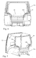
- Two wheel arches or fenders 16 are incorporated into the cab 10 at its rear.
- a roof is supported by the tops of the A-pillars 12 and C-pillars 14, a front windscreen is fitted between the two A-pillars 12 and a rear window is fitted between the upper portions of the two C-pillars 14.
- the floor or base of the cab is secured to the lower ends of the A-pillars 12 and the C-pillars 14.
- the sides of the cab are closed by doors that are taller at their front ends than at their rear ends so that they fit over the wheel fenders 16.
- console unit 18 carrying the steering wheel and various controls of the tractor and these are accessed by an operator sitting in a seat 20 located between the two wheel fenders 16.
- Each of the C-pillars 14 is formed of a tube that is bent, for example by hydroforming, to define a lower portion 14a arrange at the rear of the cab inwards of the rear wheel fenders 16 connected by a curved transition portion 14b to a curved upper portion 14c.
- the upper portions 14c lie above the wheel fenders 16 and are offset forwards from the rear of the cab relative to the lower portions 14a.
- All the sides of the frame namely the A-pillars 12, the upper portions 14c of the C-pillars 14 and roof members 22 interconnecting the upper ends of the pillars 12 and 14 are curved to be convex outwards, the pillars 12 and 14 running inwards from bottom to top.
- All the panels fitted to the frame, including the doors, the front windscreen and the rear window are correspondingly formed convex outwards. Aside from making for a more rigid cab, this design improves the aesthetics of the cab and the curved windows improve the operator's visibility.
- the construction of the C-pillars 14 also achieves improved support of the rear window, the window being supported from below by the curved transition portion 14b of the pillars. Furthermore, the offsetting of the upper portions 14c forwards from the rear of the cab serves to improve rear visibility while reducing the width of the doors to improve the strength of the cab.
Landscapes
- Engineering & Computer Science (AREA)
- Chemical & Material Sciences (AREA)
- Combustion & Propulsion (AREA)
- Transportation (AREA)
- Mechanical Engineering (AREA)
- Body Structure For Vehicles (AREA)
- Manufacture Of Alloys Or Alloy Compounds (AREA)
Applications Claiming Priority (2)
| Application Number | Priority Date | Filing Date | Title |
|---|---|---|---|
| GB0023130 | 2000-09-20 | ||
| GB0023130A GB2367038A (en) | 2000-09-20 | 2000-09-20 | Cab for an agricultural vehicle |
Publications (3)
| Publication Number | Publication Date |
|---|---|
| EP1190939A2 true EP1190939A2 (de) | 2002-03-27 |
| EP1190939A3 EP1190939A3 (de) | 2003-10-29 |
| EP1190939B1 EP1190939B1 (de) | 2008-01-23 |
Family
ID=9899843
Family Applications (1)
| Application Number | Title | Priority Date | Filing Date |
|---|---|---|---|
| EP01203332A Expired - Lifetime EP1190939B1 (de) | 2000-09-20 | 2001-09-04 | Fahrerhaus eines landwirtschaftlichen Fahrzeugs |
Country Status (5)
| Country | Link |
|---|---|
| US (1) | US6543840B2 (de) |
| EP (1) | EP1190939B1 (de) |
| AT (1) | ATE384656T1 (de) |
| DE (1) | DE60132527T2 (de) |
| GB (1) | GB2367038A (de) |
Cited By (8)
| Publication number | Priority date | Publication date | Assignee | Title |
|---|---|---|---|---|
| JP2004306793A (ja) * | 2003-04-07 | 2004-11-04 | Komatsu Ltd | スライドドアを有するキャブの構造 |
| GB2418891A (en) * | 2004-10-06 | 2006-04-12 | Cnh Belgium Nv | Cab for an agricultural vehicle |
| EP2261106A3 (de) * | 2009-06-10 | 2011-05-04 | Deere & Company | Tragrahmenstruktur einer Fahrkabine eines Fahrzeugs |
| WO2012087502A2 (en) | 2010-12-22 | 2012-06-28 | Caterpillar Inc. | Frame for a cab of a mobile machine |
| WO2013010705A1 (en) * | 2011-07-18 | 2013-01-24 | Valtra Oy Ab | Rollover protection structure for an agricultural tractor and method of manufacture |
| AT14589U1 (de) * | 2013-12-13 | 2016-02-15 | Lely Patent Nv | Fahrzeug mit mindestens einem Rad und einem Radkasten |
| ITUB20150356A1 (it) * | 2015-05-08 | 2016-11-08 | Denso Thermal Systems Spa | Cabina di un trattore. |
| EP3798031A1 (de) | 2019-09-24 | 2021-03-31 | CLAAS Tractor S.A.S. | Landwirtschaftliche arbeitsmaschine |
Families Citing this family (29)
| Publication number | Priority date | Publication date | Assignee | Title |
|---|---|---|---|---|
| EP1432606B1 (de) * | 2001-10-02 | 2005-12-28 | Magna International Inc | Gitterrohrrahmen für lastwagen-führerhaus |
| JP4201126B2 (ja) * | 2003-04-10 | 2008-12-24 | 株式会社小松製作所 | 建設機械のキャブ |
| US7290829B2 (en) * | 2004-06-29 | 2007-11-06 | Kubota Corporation | Working vehicle with a cab |
| GB2441484B8 (en) * | 2005-07-19 | 2010-07-28 | Komatsu Mfg Co Ltd | Cab structure for construction machine. |
| US7677652B2 (en) * | 2006-03-29 | 2010-03-16 | Nissan Technical Center North America, Inc. | Roof inner body structure |
| JP5080209B2 (ja) * | 2007-11-07 | 2012-11-21 | 株式会社クボタ | キャビン |
| US9235644B2 (en) * | 2008-07-14 | 2016-01-12 | Qualcomm Incorporated | Operator, device and platform independent aggregation, cross-platform translation, enablement and distribution of user activity catalogs |
| USD594480S1 (en) | 2008-09-30 | 2009-06-16 | Clark Equipment Company | Telehandler cab |
| US8485589B2 (en) * | 2010-03-30 | 2013-07-16 | Kubota Corporation | Cabin system |
| CN103180518B (zh) * | 2010-10-20 | 2015-11-25 | 沃尔沃建造设备有限公司 | 具有倾翻保护结构的施工机械驾驶室 |
| GB201104086D0 (en) * | 2011-03-10 | 2011-04-27 | Agco Int Gmbh | Wheel fender |
| GB201119308D0 (en) * | 2011-11-09 | 2011-12-21 | Valtra Oy Ab | Tractor cabs |
| JP5379895B2 (ja) * | 2012-08-30 | 2013-12-25 | 株式会社クボタ | キャビン |
| US8702154B1 (en) * | 2013-02-07 | 2014-04-22 | Caterpillar Inc. | Cab frame with integrated rollover protective structure |
| JP2014166810A (ja) * | 2013-02-28 | 2014-09-11 | Iseki & Co Ltd | 作業車両のキャビン |
| USD732261S1 (en) * | 2014-02-10 | 2015-06-16 | Src Innovations, Llc | Bagging machine cabin |
| US9346495B2 (en) * | 2014-04-21 | 2016-05-24 | Caterpillar Inc. | Machine cabin having improved operator visibility |
| USD747839S1 (en) * | 2014-07-29 | 2016-01-19 | Crown Equipment Corporation | Fork lift truck |
| USD746013S1 (en) * | 2014-07-29 | 2015-12-22 | Crown Equipment Corporation | Overhead guard for a lift truck |
| USD747840S1 (en) * | 2014-07-29 | 2016-01-19 | Crown Equipment Corporation | Fork lift truck |
| JP6140215B2 (ja) * | 2015-04-22 | 2017-05-31 | 株式会社クボタ | キャビン |
| RU178477U1 (ru) * | 2017-07-24 | 2018-04-04 | Тенгизи Джемалиевич Дзоценидзе | Кабина колесного трактора |
| CN108100055A (zh) * | 2017-11-24 | 2018-06-01 | 中联重机股份有限公司 | 一种拖拉机驾驶室 |
| JP6602938B2 (ja) * | 2018-11-09 | 2019-11-06 | 株式会社クボタ | キャビン |
| JP7259122B2 (ja) * | 2019-10-09 | 2023-04-17 | 株式会社クボタ | キャビン |
| JP6874086B2 (ja) * | 2019-10-09 | 2021-05-19 | 株式会社クボタ | キャビン |
| US11110969B2 (en) * | 2020-01-10 | 2021-09-07 | Caterpillar Inc. | Quick release floor panel system for a work machine |
| EP3978690B1 (de) * | 2020-09-30 | 2025-11-26 | Kobelco Construction Machinery Co., Ltd. | Arbeitsmaschine |
| WO2025143053A1 (ja) * | 2023-12-27 | 2025-07-03 | 株式会社クボタ | キャビン及びキャビンに用いられる異形管 |
Family Cites Families (11)
| Publication number | Priority date | Publication date | Assignee | Title |
|---|---|---|---|---|
| FR2122736A5 (de) * | 1971-01-21 | 1972-09-01 | Kettler Paul Erich | |
| US3787085A (en) * | 1972-06-23 | 1974-01-22 | Deere & Co | Tractor roll-over protective frame |
| US3985386A (en) * | 1975-09-15 | 1976-10-12 | Deere & Company | Vehicle roll-over protective structure |
| AT380443B (de) * | 1981-08-19 | 1986-05-26 | Steyr Daimler Puch Ag | Fahrerschutzrahmen fuer ackerschlepper |
| US6189195B1 (en) * | 1995-08-22 | 2001-02-20 | Medrad, Inc. | Manufacture of prefilled syringes |
| US5820199A (en) * | 1995-11-08 | 1998-10-13 | Caterpillar Inc. | Frame assembly for an operator's compartment |
| JP3229213B2 (ja) * | 1996-08-05 | 2001-11-19 | 本田技研工業株式会社 | 自動車の車体構造 |
| DE69721445T2 (de) * | 1996-11-12 | 2003-11-20 | Cnh Belgium N.V., Zedelgem | Auslegung einer Kabine für Getreide- Mähdrescher mit verbesserter Sicht, Wartung und Raumausnutzung |
| US6149228A (en) * | 1998-12-09 | 2000-11-21 | Deere & Company | Modular operator enclosure |
| US6325449B1 (en) * | 2000-06-08 | 2001-12-04 | Deere & Company | ROPS structure for work vehicle |
| DE60001403T2 (de) * | 2000-07-28 | 2003-10-30 | Same Deutz-Fahr S.P.A., Treviglio | Kabinerahmen für landwirtschaftliche Maschine |
-
2000
- 2000-09-20 GB GB0023130A patent/GB2367038A/en not_active Withdrawn
-
2001
- 2001-09-04 AT AT01203332T patent/ATE384656T1/de not_active IP Right Cessation
- 2001-09-04 EP EP01203332A patent/EP1190939B1/de not_active Expired - Lifetime
- 2001-09-04 DE DE60132527T patent/DE60132527T2/de not_active Expired - Lifetime
- 2001-09-18 US US09/954,854 patent/US6543840B2/en not_active Expired - Lifetime
Cited By (11)
| Publication number | Priority date | Publication date | Assignee | Title |
|---|---|---|---|---|
| JP2004306793A (ja) * | 2003-04-07 | 2004-11-04 | Komatsu Ltd | スライドドアを有するキャブの構造 |
| EP1466767A3 (de) * | 2003-04-07 | 2008-09-17 | Komatsu Ltd. | Schiebetür für eine Nutzfahrzeugkabine |
| US7517007B2 (en) | 2003-04-07 | 2009-04-14 | Komatsu Ltd. | Slide door-carrying cab |
| GB2418891A (en) * | 2004-10-06 | 2006-04-12 | Cnh Belgium Nv | Cab for an agricultural vehicle |
| EP2261106A3 (de) * | 2009-06-10 | 2011-05-04 | Deere & Company | Tragrahmenstruktur einer Fahrkabine eines Fahrzeugs |
| WO2012087502A2 (en) | 2010-12-22 | 2012-06-28 | Caterpillar Inc. | Frame for a cab of a mobile machine |
| EP2655752A4 (de) * | 2010-12-22 | 2016-09-21 | Caterpillar Inc | Rahmen für ein fahrerhaus einer mobilen maschine |
| WO2013010705A1 (en) * | 2011-07-18 | 2013-01-24 | Valtra Oy Ab | Rollover protection structure for an agricultural tractor and method of manufacture |
| AT14589U1 (de) * | 2013-12-13 | 2016-02-15 | Lely Patent Nv | Fahrzeug mit mindestens einem Rad und einem Radkasten |
| ITUB20150356A1 (it) * | 2015-05-08 | 2016-11-08 | Denso Thermal Systems Spa | Cabina di un trattore. |
| EP3798031A1 (de) | 2019-09-24 | 2021-03-31 | CLAAS Tractor S.A.S. | Landwirtschaftliche arbeitsmaschine |
Also Published As
| Publication number | Publication date |
|---|---|
| GB2367038A (en) | 2002-03-27 |
| DE60132527D1 (de) | 2008-03-13 |
| DE60132527T2 (de) | 2008-04-30 |
| EP1190939A3 (de) | 2003-10-29 |
| US20020079721A1 (en) | 2002-06-27 |
| EP1190939B1 (de) | 2008-01-23 |
| ATE384656T1 (de) | 2008-02-15 |
| GB0023130D0 (en) | 2000-11-01 |
| US6543840B2 (en) | 2003-04-08 |
Similar Documents
| Publication | Publication Date | Title |
|---|---|---|
| EP1190939B1 (de) | Fahrerhaus eines landwirtschaftlichen Fahrzeugs | |
| US4234225A (en) | Rear reinforcement structure for automobile bodies | |
| EP1147947B1 (de) | Fahrgastzelle für den Fahrer eines Ackerschleppers | |
| JP4284793B2 (ja) | 車両の上部車体構造 | |
| JPH0351621B2 (de) | ||
| CA2503477C (en) | Frame for a motor vehicle | |
| US7467821B2 (en) | Vehicle body structure for a passenger car equipped with a fastback | |
| EP1177968B1 (de) | Stossenergieabsorbierende Struktur für ein Kraftfahrzeug | |
| JP3031642B2 (ja) | 自動車の前部車体構造 | |
| GB2461508A (en) | Tractor cab with improved visibility | |
| US20060017272A1 (en) | Supporting member for a fender | |
| JP3311648B2 (ja) | 自動車のフレームメンバ補強構造 | |
| JPS646070B2 (de) | ||
| KR960005857B1 (ko) | 차량의 앞부분 차체구조 | |
| JPWO2002100671A1 (ja) | フロントピラーによる視界死角軽減のためのフロントガラスの固定構造 | |
| JP4432225B2 (ja) | 車両の車体構造 | |
| JPH0445990Y2 (de) | ||
| JP2964494B2 (ja) | 自動車の前部車体構造 | |
| JPS61249875A (ja) | 自動車の前部車体構造 | |
| JP4251567B2 (ja) | 車両のフロア構造 | |
| GB2469649A (en) | Utility vehicle cab | |
| JP2955689B2 (ja) | 自動車の前部車体構造 | |
| JP2724507B2 (ja) | トラックと乗用車の兼用車体 | |
| JP3136584B2 (ja) | 車体のカウル構造 | |
| GB1575001A (en) | Truck cabs |
Legal Events
| Date | Code | Title | Description |
|---|---|---|---|
| PUAI | Public reference made under article 153(3) epc to a published international application that has entered the european phase |
Free format text: ORIGINAL CODE: 0009012 |
|
| AK | Designated contracting states |
Kind code of ref document: A2 Designated state(s): AT BE CH CY DE DK ES FI FR GB GR IE IT LI LU MC NL PT SE TR |
|
| AX | Request for extension of the european patent |
Free format text: AL;LT;LV;MK;RO;SI |
|
| RAP1 | Party data changed (applicant data changed or rights of an application transferred) |
Owner name: CNH U.K. LIMITED |
|
| PUAL | Search report despatched |
Free format text: ORIGINAL CODE: 0009013 |
|
| AK | Designated contracting states |
Kind code of ref document: A3 Designated state(s): AT BE CH CY DE DK ES FI FR GB GR IE IT LI LU MC NL PT SE TR |
|
| AX | Request for extension of the european patent |
Extension state: AL LT LV MK RO SI |
|
| RIC1 | Information provided on ipc code assigned before grant |
Ipc: 7B 60H 3/06 B Ipc: 7B 62D 33/06 A |
|
| 17P | Request for examination filed |
Effective date: 20040422 |
|
| AKX | Designation fees paid |
Designated state(s): AT BE CH CY DE DK ES FI FR GB GR IE IT LI LU MC NL PT SE TR |
|
| GRAP | Despatch of communication of intention to grant a patent |
Free format text: ORIGINAL CODE: EPIDOSNIGR1 |
|
| GRAS | Grant fee paid |
Free format text: ORIGINAL CODE: EPIDOSNIGR3 |
|
| GRAA | (expected) grant |
Free format text: ORIGINAL CODE: 0009210 |
|
| AK | Designated contracting states |
Kind code of ref document: B1 Designated state(s): AT BE CH CY DE DK ES FI FR GB GR IE IT LI LU MC NL PT SE TR |
|
| REG | Reference to a national code |
Ref country code: GB Ref legal event code: FG4D |
|
| REG | Reference to a national code |
Ref country code: CH Ref legal event code: EP |
|
| REG | Reference to a national code |
Ref country code: IE Ref legal event code: FG4D |
|
| REF | Corresponds to: |
Ref document number: 60132527 Country of ref document: DE Date of ref document: 20080313 Kind code of ref document: P |
|
| NLV1 | Nl: lapsed or annulled due to failure to fulfill the requirements of art. 29p and 29m of the patents act | ||
| PG25 | Lapsed in a contracting state [announced via postgrant information from national office to epo] |
Ref country code: ES Free format text: LAPSE BECAUSE OF FAILURE TO SUBMIT A TRANSLATION OF THE DESCRIPTION OR TO PAY THE FEE WITHIN THE PRESCRIBED TIME-LIMIT Effective date: 20080504 Ref country code: CH Free format text: LAPSE BECAUSE OF FAILURE TO SUBMIT A TRANSLATION OF THE DESCRIPTION OR TO PAY THE FEE WITHIN THE PRESCRIBED TIME-LIMIT Effective date: 20080123 Ref country code: LI Free format text: LAPSE BECAUSE OF FAILURE TO SUBMIT A TRANSLATION OF THE DESCRIPTION OR TO PAY THE FEE WITHIN THE PRESCRIBED TIME-LIMIT Effective date: 20080123 Ref country code: FI Free format text: LAPSE BECAUSE OF FAILURE TO SUBMIT A TRANSLATION OF THE DESCRIPTION OR TO PAY THE FEE WITHIN THE PRESCRIBED TIME-LIMIT Effective date: 20080123 |
|
| ET | Fr: translation filed | ||
| REG | Reference to a national code |
Ref country code: CH Ref legal event code: PL |
|
| PG25 | Lapsed in a contracting state [announced via postgrant information from national office to epo] |
Ref country code: AT Free format text: LAPSE BECAUSE OF FAILURE TO SUBMIT A TRANSLATION OF THE DESCRIPTION OR TO PAY THE FEE WITHIN THE PRESCRIBED TIME-LIMIT Effective date: 20080123 |
|
| PG25 | Lapsed in a contracting state [announced via postgrant information from national office to epo] |
Ref country code: PT Free format text: LAPSE BECAUSE OF FAILURE TO SUBMIT A TRANSLATION OF THE DESCRIPTION OR TO PAY THE FEE WITHIN THE PRESCRIBED TIME-LIMIT Effective date: 20080623 Ref country code: BE Free format text: LAPSE BECAUSE OF FAILURE TO SUBMIT A TRANSLATION OF THE DESCRIPTION OR TO PAY THE FEE WITHIN THE PRESCRIBED TIME-LIMIT Effective date: 20080123 |
|
| PG25 | Lapsed in a contracting state [announced via postgrant information from national office to epo] |
Ref country code: SE Free format text: LAPSE BECAUSE OF FAILURE TO SUBMIT A TRANSLATION OF THE DESCRIPTION OR TO PAY THE FEE WITHIN THE PRESCRIBED TIME-LIMIT Effective date: 20080423 Ref country code: DK Free format text: LAPSE BECAUSE OF FAILURE TO SUBMIT A TRANSLATION OF THE DESCRIPTION OR TO PAY THE FEE WITHIN THE PRESCRIBED TIME-LIMIT Effective date: 20080123 Ref country code: NL Free format text: LAPSE BECAUSE OF FAILURE TO SUBMIT A TRANSLATION OF THE DESCRIPTION OR TO PAY THE FEE WITHIN THE PRESCRIBED TIME-LIMIT Effective date: 20080123 |
|
| PLBE | No opposition filed within time limit |
Free format text: ORIGINAL CODE: 0009261 |
|
| STAA | Information on the status of an ep patent application or granted ep patent |
Free format text: STATUS: NO OPPOSITION FILED WITHIN TIME LIMIT |
|
| 26N | No opposition filed |
Effective date: 20081024 |
|
| PG25 | Lapsed in a contracting state [announced via postgrant information from national office to epo] |
Ref country code: MC Free format text: LAPSE BECAUSE OF NON-PAYMENT OF DUE FEES Effective date: 20080930 |
|
| PG25 | Lapsed in a contracting state [announced via postgrant information from national office to epo] |
Ref country code: CY Free format text: LAPSE BECAUSE OF FAILURE TO SUBMIT A TRANSLATION OF THE DESCRIPTION OR TO PAY THE FEE WITHIN THE PRESCRIBED TIME-LIMIT Effective date: 20080123 Ref country code: IE Free format text: LAPSE BECAUSE OF NON-PAYMENT OF DUE FEES Effective date: 20080904 |
|
| PG25 | Lapsed in a contracting state [announced via postgrant information from national office to epo] |
Ref country code: LU Free format text: LAPSE BECAUSE OF NON-PAYMENT OF DUE FEES Effective date: 20080904 |
|
| PG25 | Lapsed in a contracting state [announced via postgrant information from national office to epo] |
Ref country code: TR Free format text: LAPSE BECAUSE OF FAILURE TO SUBMIT A TRANSLATION OF THE DESCRIPTION OR TO PAY THE FEE WITHIN THE PRESCRIBED TIME-LIMIT Effective date: 20080123 |
|
| PG25 | Lapsed in a contracting state [announced via postgrant information from national office to epo] |
Ref country code: GR Free format text: LAPSE BECAUSE OF FAILURE TO SUBMIT A TRANSLATION OF THE DESCRIPTION OR TO PAY THE FEE WITHIN THE PRESCRIBED TIME-LIMIT Effective date: 20080424 |
|
| PGFP | Annual fee paid to national office [announced via postgrant information from national office to epo] |
Ref country code: DE Payment date: 20140715 Year of fee payment: 14 |
|
| PGFP | Annual fee paid to national office [announced via postgrant information from national office to epo] |
Ref country code: GB Payment date: 20140714 Year of fee payment: 14 Ref country code: FR Payment date: 20140710 Year of fee payment: 14 |
|
| PGFP | Annual fee paid to national office [announced via postgrant information from national office to epo] |
Ref country code: IT Payment date: 20140926 Year of fee payment: 14 |
|
| REG | Reference to a national code |
Ref country code: DE Ref legal event code: R119 Ref document number: 60132527 Country of ref document: DE |
|
| PG25 | Lapsed in a contracting state [announced via postgrant information from national office to epo] |
Ref country code: IT Free format text: LAPSE BECAUSE OF NON-PAYMENT OF DUE FEES Effective date: 20150904 |
|
| GBPC | Gb: european patent ceased through non-payment of renewal fee |
Effective date: 20150904 |
|
| REG | Reference to a national code |
Ref country code: FR Ref legal event code: ST Effective date: 20160531 |
|
| PG25 | Lapsed in a contracting state [announced via postgrant information from national office to epo] |
Ref country code: GB Free format text: LAPSE BECAUSE OF NON-PAYMENT OF DUE FEES Effective date: 20150904 Ref country code: DE Free format text: LAPSE BECAUSE OF NON-PAYMENT OF DUE FEES Effective date: 20160401 |
|
| PG25 | Lapsed in a contracting state [announced via postgrant information from national office to epo] |
Ref country code: FR Free format text: LAPSE BECAUSE OF NON-PAYMENT OF DUE FEES Effective date: 20150930 |