EP1192890A2 - Filterbeutel für einen Staubsauger - Google Patents
Filterbeutel für einen Staubsauger Download PDFInfo
- Publication number
- EP1192890A2 EP1192890A2 EP01120834A EP01120834A EP1192890A2 EP 1192890 A2 EP1192890 A2 EP 1192890A2 EP 01120834 A EP01120834 A EP 01120834A EP 01120834 A EP01120834 A EP 01120834A EP 1192890 A2 EP1192890 A2 EP 1192890A2
- Authority
- EP
- European Patent Office
- Prior art keywords
- holding plate
- dust bag
- bag
- fold
- edge
- Prior art date
- Legal status (The legal status is an assumption and is not a legal conclusion. Google has not performed a legal analysis and makes no representation as to the accuracy of the status listed.)
- Granted
Links
Images


Classifications
-
- A—HUMAN NECESSITIES
- A47—FURNITURE; DOMESTIC ARTICLES OR APPLIANCES; COFFEE MILLS; SPICE MILLS; SUCTION CLEANERS IN GENERAL
- A47L—DOMESTIC WASHING OR CLEANING; SUCTION CLEANERS IN GENERAL
- A47L9/00—Details or accessories of suction cleaners, e.g. mechanical means for controlling the suction or for effecting pulsating action; Storing devices specially adapted to suction cleaners or parts thereof; Carrying-vehicles specially adapted for suction cleaners
- A47L9/10—Filters; Dust separators; Dust removal; Automatic exchange of filters
- A47L9/14—Bags or the like; Rigid filtering receptacles; Attachment of, or closures for, bags or receptacles
- A47L9/1427—Means for mounting or attaching bags or filtering receptacles in suction cleaners; Adapters
- A47L9/1436—Connecting plates, e.g. collars, end closures
Definitions
- the invention relates to a filter bag for a Vacuum cleaner with a holding plate and a dust bag, the dust bag being tubular is with a closed, free end area and an area connected to the holding plate.
- Filter bags of the type in question are of different types Embodiments known, for example with dust bags made of a paper material, which on usual Tubular bag systems can be processed.
- the region to be connected to the holding plate of such a dust bag made of a paper material is folded into a so-called block bottom and after that glued to the holding plate, for example.
- the edge folds that limit the filling space in length are not, as is known in the prior art, directly attached under the holding plate, but rather are connected via the transverse fold formed, which preferably results in a mirror-symmetrical arrangement of the edge folds essentially over the entire length of the filling space ,
- the filling opening in the holding plate is not covered by a dust bag media layer due to the selected shape.
- the filter bag according to the invention is not manufactured according to the block bottom principle, in which the holding plate is arranged, covering the free open end of the tubular dust bag, but rather by arranging the holding plate in an end region of the tubular dust bag, preferably with full-surface gluing with a is formed, there is initially an asymmetrical arrangement of the edge folds delimiting the filling space, as viewed before the filter bag is set up, since the edge fold that is further away from the one closed, free end region of the dust bag is longer by the width of the holding plate than the edge fold closer to the closed, free end region, which edge fold length difference is compensated for by the design of the transverse fold according to the invention.
- a second closed end region is provided, which extends in the immediate vicinity of an edge of the holding plate.
- the filter bag according to the invention has a filling space length which corresponds to a multiple of the holding plate width, so in a preferred embodiment approximately three to five times the holding plate width. With a maximum overhang of less than 1 cm on both sides, the width of the filter bag is adjusted approximately to the width of the holding plate.
- the anther depth preferably corresponds to the holding plate length measured transversely to the anther tube extension. Due to the selected geometry, the filter bag according to the invention can be used in filter cassettes, the cassette opening of which is adapted to the holding plate geometry or is slightly larger.
- the hose material has an opening spaced apart from the second end region, which opening is assigned to a passage opening of the holding plate.
- the filter bag according to the invention has a design in which the dust bag transverse fold, associated with an edge of the holding plate, merges into a fold that lies on the outside of the dust bag material. This bead-like folding is in the installed state of the filter bag, ie in the operating state, covered under the holding plate and thus does not protrude into the insertion path of the filter bag when it is inserted into the filter cassette of the vacuum cleaner.
- the overfolding is fixed in itself.
- the fold can be glued or welded.
- the overfolding is fixed on the holding plate, so further preferably in the area of the underside of the holding plate.
- the usual, possibly also multi-layer paper material can be selected as the dust bag material.
- the dust bag material is a nonwoven, for example a meltblown material, the nonwoven material further having a substantially greater thickness than a paper filter material.
- the tube material is arranged to form a longitudinal edge fold drawn in on both sides.
- the depth of the longitudinal edge folds and the dust bag length dictate the dust holding volume of the filter bag, it being further provided in a preferred embodiment that the depth of the longitudinal edge fold, at least in the case of a nonwoven material, depends on the length of the transverse fold, the width of the holding plate, and the thickness the dust bag material and the dimension of the transverse fold protrusion resulting in relation to an edge of the holding plate.
- the invention further relates to a method for Production of a filter bag with a holding plate and a dust bag, initially a tube-like Arrangement of the dust bag with longitudinal edge folding is made and this then with the formation of a second end region is separated.
- Such procedures for the production of a filter bag in question standing type are known. For example, dust bags from a paper filter material on a flow pack processed, with the second end region folded for arrest with the holding plate as a block bottom becomes.
- it is proposed that then the two opposite, free Ends are closed and the holding plate after Forming a corresponding opening in the anther material, assigned to one of the end areas with which Anther is arrested.
- Filter material separated from an endless tube for example, with this separation at the same time closing the free ends of the filter material.
- the holding plate is then on the surface the filter material, assigned to an end region thereof, arrested, e.g. glued.
- the assigned, closed end area extends in immediate Proximity, parallel to one across Longitudinal edge of the hose extending in the direction of hose extension the holding plate, preferably a distance between the edge of the holding plate and the associated one closed end of less than 1 cm is selected.
- the filter material hose can be on a conventional Hose drawing system to be made.
- the closing the open narrow sides of the filter material hose can be done by gluing, welding or forming a wedge fold respectively.
- the holding plate On this flat, all-round closed bag, the holding plate is welded on or glued so that the long side of the holding plate parallel and direct or at a short distance then to the short side of the bag rectangle lies.
- a Pint from the excess filter material on one side of the bag educated It is proposed that the dust bag material area adhered to the holding plate in the longitudinal direction of the dust bag on the other End area is folded over, forming a Crossfolder supernatant. It is also proposed that afterwards the cross fold overhang in the longitudinal direction of the dust bag folded over to the other end area becomes. This folding is then in itself fixed, e.g. welded or on the holding plate fixed, e.g. welded on. Another alternative may be this overfolding can also be separated.
- the according to the invention Processed filter bag has one, preferably mirror-symmetrical arrangement of the over the Filling length of the dust bag extending edge folds so that after setting up the filter bag an optimal filling of the same is made possible.
- the dust bag material is not or not essential, d. H. with less than 1 cm over the Basic geometry of the holding plate protrudes so that the Manufactured filter bags used in vacuum cleaner cartridges can be, the cassette opening essentially corresponds to the holding plate layout.
- the invention Process is for processing dust bags Can be used from a paper filter material. Prefers however, this method comes with a nonwoven filter material for use.
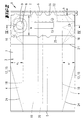
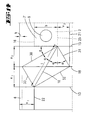
- a filter bag 1 for a not shown Vacuum cleaner consisting of a holding plate 2 and one in the illustrated embodiment a non-woven material dust bag 3.
- the dust bag 3 is tubular and has a longitudinal edge fold 4 on both sides.
- the two free end regions 5 and 6 of the hose-like Filter material is closed, for example by gluing, Welding or formation of a fold.
- the holding plate 2 is almost the entire surface with the Dust bag material arrested, e.g. glued, causing a dust bag material section below the holding plate 2 7 'results.
- This section of material 7 ' is the second end 6 of the tubular dust bag 3 assigned and has a - not shown in Fig. 1 - Opening 8, which a - also in Fig. 1 not shown - passage 9 of the Holding plate 2 is assigned.
- the material section 7 ' extends almost over the total width of the holding plate 2. Below this the holding plate 2 adhering material section 7 ' extends an outwardly bulging anther transverse fold 10, the extension length of which is at least Holding plate width b corresponds. In the illustrated In the embodiment, the transverse fold length is greater chosen as the holding plate width b.
- This transverse fold 10 extends from the second End 6 facing away from the edge 11 of the holding plate 2 arrested material section 7 'starting in the area opposite this edge 11 and merges here into a fold 12 of the edge 11 opposite, over the filling space length 1 of the anther 3 extending edge fold 13.
- This overfold 12 is formed from a cross fold overhang 14, which results from the versus facing the edge 11 of the material section 7 ' Edge fold 15 greater length of the edge fold 13, the Edge fold 13 starting with the lower free end 5, including the fold 12 on the upper free, closed end 6 ends.
- the second, closed end region 6 extends in close proximity to a longitudinal edge 16 of the Holding plate 2, here a projection dimension a of less is chosen as 1 cm.
- the mentioned folding 12 can be fixed in itself, for example. glued or welded.
- the filter bag 1 has a symmetrical one Arrangement of the edge folds delimiting the filling space 17 13 and 15. Furthermore, the filling space is 17th at least with respect to the width of the holding plate 2 symmetrical to the passage opening 9 of the holding plate 2 aligned so that the filling of the filter bag 1 is guaranteed in an optimal manner. according to the proposed folding of the anther material and the associated alignment of the gussets 13 and 15 there is no bag material layer directly under the passage opening 9 of the holding plate 2 what it would be difficult to fill the filter bag 1.
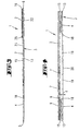
- Fig. 2 is a tubular, flat lying dust bag 3 shown, the free, narrow-sided Ends 5 and 6 are closed, for example by gluing or welding.
- the holding plate 2 is in an end region, the closed one assigned to the second end 6, on the material layer 7 placed and there with the filter material in the area a material section 7 'arrested, for example glued.
- the length of the holding plate 2 corresponds essentially to this the across the hose extension of the dust bag 3 measured width of the same, with a further Ratio of holding plate width b to hose direction measured dust bag length - length between the End 5 and 6- is selected from about 1: 4 to 1: 5.
- the arrangement of the holding plate 2 is further selected so that that a slight protrusion between the end 6 associated longitudinal edge 16 of the holding plate 2 and this end 6 is less than 1 cm.
- an opening 8 is provided Associated with the passage opening 9 of the holding plate 2 is in the upper material layer 7 of the dust bag 3 an opening 8 is provided.
- the one in the upper material layer 7 provided pre-break 21 in its distance parallel to the end 6 depending on the width k the weld 6, the holding plate width b and Length s of a loop 23 - which is described in more detail is- is selected.
- the distance of the bottom, in the Material layer 19 trained preliminary break 22 to the parallel edge of the end 6 is dependent from the weld seam width k, the holding plate width b and the dust bag material thickness d selected.
- FIG. 5 is a development of a cut Dust bag 3 shown.
- the holding plate to be assigned 2 is shown in dash-dotted line style.
- FIG. 5 shows that the upper one Material layer 7 assigned pre-break 21 over the Width h of the upper layer of material 7 on both sides extends to the folded edges 18, whereas the pre-break assigned to the lower layer of material 19 22 only up to the edge fold 13 that bounds them runs.
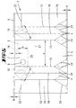
- FIG. 6 to 8 is a schematic representation the further process for the preparation of the invention
- Filter bag 1 shown. 6 is schematic a section through the holding plate 2 shown, below which is the end area facing the end 6 of the tubular dust bag 3 extends. It are further schematically the pre-breaks 21 and 22 detect. Due to the chosen arrangement of the holding plate 2 on the upper layer of material 7 show the layers of material 7, 19 or their edge folds 13, 15 in their Longitudinal extension - related to the assigned retaining plate longitudinal edge 16 (Edge folds of the upper Material layer 7) and the retaining plate longitudinal edge 25 (Edge folds of the lower layer of material 19) - different Lengths, what difference is about the holding plate width b corresponds. Setting up a dust bag 3 from the situation according to FIG. 6 would be an asymmetrical one Bag shape and an accompanying bad Pull the filter bag 1 into place.
- FIG. 8 can be recognized by the folding technique according to the invention a mirror-symmetrical arrangement of the material layers or the edge folds in the erected position of the Filter bag 1 given.
- the cross fold protrusion 14 or the loop 23 can finally be fixed in itself. Alternatively, you can this loop is also attached to the outside of the material layer 19 , alternatively also a separation of the protruding material.
- the depth x of the longitudinal edge folds 4, d. H. the parallel Distance between edge fold 13 or 15 and the inside Folding edge 18 depends on the length t the transverse fold 10, the width b of the holding plate 2, the Thickness d of the anther material and the related on the edge 16 of the holding plate 2 resulting dimension a of the cross fold overhang 14 selected.
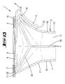
- FIG. 9 to 12 show the folding method using a concrete embodiment.
- Fig. 11 is the post-folding position shown.
- transverse fold 10 which bulges outwards over the width b of the Holding plate 2 extends.
- both the Cross fold 10 as well as that on both sides of the cross fold 10 symmetrically arranged folding edges 30 to 33 as breaks educated. So they can be in the manufacturing process by mechanical compression or ultrasonic welding be educated.
- These fold edges 30 to 33 span a rectangle with the transverse fold 10 as Diagonal, with further a longitudinal folding edge 30 both to the edge fold 15 and to the transverse fold 10 in one Alpha angle of 30 °.
- the folded sections above and below the material layer section 7 'between the imaginary holding plate edge 25 and the protrusion 21 and the further protrusion 22 and the free edge have the same heights V 1 , V 2 , with an extension of the protrusion 22 in the upper imaginary edge of the holding plate runs in.
- widths U 1 and U 2 of the longitudinal edge folds 4 measured transversely to the longitudinal extent of the edge folds 13, 15 are dimensioned the same.
Landscapes
- Engineering & Computer Science (AREA)
- Mechanical Engineering (AREA)
- Filters For Electric Vacuum Cleaners (AREA)
- Filtering Of Dispersed Particles In Gases (AREA)
Abstract
Description
Die Füllöffnung in der Halteplatte ist im Betriebszustand des Filterbeutels durch die gewählte Ausformung nicht durch eine Staubbeutel-Medienlage verdeckt. Dadurch bedingt, dass der erfindungsgemäße Filterbeutel nicht nach dem Klotzbodenprinzip, bei welchem die Halteplatte, das freie offene Ende des schlauchartigen Staubbeutels überdeckend, angeordnet ist, hergestellt ist, sondern vielmehr durch Anordnung der Halteplatte in einem Endbereich des schlauchartigen Staubbeutels unter bevorzugt vollflächiger Verklebung mit einer randseitigen, oberen Medienlage des Staubbeutels geformt ist, ergibt sich zunächst eine in Füllraumlänge betrachtete asymmetrische Anordnung der den Füllraum begrenzenden Randfalten, da die vor dem Aufstellen des Filterbeutels zunächst von dem einen verschlossenen, freien Endbereich des Staubbeutels weiter entfernte Randfalte eine um die Halteplattenbreite größere Länge aufweist als die, dem verschlossenen, freien Endbereich näher zugewandte Randfalte, welche Randfalten-Längendifferenz durch die Ausbildung der erfindungsgemäßen Querfalte ausgeglichen ist. In einer weiteren Ausgestaltung ist ein zweiter verschlossener Endbereich vorgesehen, der sich in unmittelbarer Nähe zu einer Randkante der Halteplatte erstreckt. Zufolge dieser Ausgestaltung ist ein Filterbeutel realisiert, der ohne Ausbildung eines bekannten Klotzbodens im aufgestellten Zustand des Filterbeutels, d. h. im Betriebszustand, einen geringen Überstand des Staubbeutelmaterials über die Halteplattenbreite aufweist, so bspw. einen Überstand von weniger als einem Zentimeter. In vorteilhafter Weise verlaufen die verschlossenen Endbereiche des schlauchartig ausgebildeten Staubbeutels parallel zu den Längsrandkanten der Halteplatte, wobei der zweite verschlossene Endbereich in unmittelbarer Nähe zur zugeordneten Längsrandkante der Halteplatte, bspw. mit einem Abstand von 1 cm zu dieser verläuft. Der erfindungsgemäße Filterbeutel weist im aufgestellten Zustand eine Füllraumlänge auf, welche einem Mehrfachen der Halteplattenbreite entspricht, so in einer bevorzugten Ausgestaltung etwa dem drei- bis fünffachen der Halteplattenbreite. Die Filterbeutelbreite ist bei einem beidseitigeh, maximalen Überstand von weniger als 1 cm etwa der Breite der Halteplatte angepasst. Die Staubbeuteltiefe entspricht bevorzugt der quer zur Staubbeutel-Schlaucherstreckung gemessenen Halteplattenlänge. Zufolge der gewählten Geometrie ist der erfindungsgemäße Filterbeutel in Filterkassetten einsetzbar, deren Kassettenöffnung angepasst an die Halteplattengeometrie oder geringfügig größer ausgebildet ist. In weiterer Ausgestaltung des Erfindungsgegenstandes ist vorgesehen, dass das Schlauchmaterial beabstandet zu dem zweiten Endbereich eine Öffnung aufweist, die einer Durchtrittsöffnung der Halteplatte zugeordnet ist. Darüber hinaus weist der erfindungsgemäße Filterbeutel eine Ausbildung auf, bei welcher die Staubbeutel-Querfalte zugeordnet einer Randkante der Halteplatte in einer außen auf dem Staubbeutelmaterial aufliegenden Überfaltung übergeht. Diese wulstartige Überfaltung liegt im aufgestellten Zustand des Filterbeutels, d. h. im Betriebszustand, verdeckt unterhalb der Halteplatte und ragt somit nicht in den Einführweg des Filterbeutels beim Einsetzen desselben in die Filterkassette des Staubsaugers ein. Diesbezüglich wird bevorzugt, dass die Überfaltung in sich fixiert ist. So kann bspw. die Überfaltung je nach Beutelmaterial in sich verklebt oder verschweißt sein. Darüber hinaus ist es denkbar, dass die Überfaltung an der Halteplatte fixiert ist, so weiter bevorzugt im Bereich der Unterseite der Halteplatte. Als Staubbeutelmaterial kann üblicher, gegebenenfalls auch mehrlagiger Papierwerkstoff gewählt sein. In einer bevorzugten Ausgestaltung ist jedoch vorgesehen, dass das Staubbeutelmaterial ein Vlies, bspw. ein Meltblown-Material ist, wobei weiter das Vliesmaterial eine wesentlich größere Dicke als ein Papierfiltermaterial aufweist. In weiterer Ausgestaltung des Erfindungsgegenstandes ist unabhängig von der Staubbeutel-Materialwahl vorgesehen, dass das Schlauchmaterial unter Bildung einer beidseitig eingezogenen Längsrandfalte angeordnet ist. Durch die Tiefe der Längsrandfalten und die Staubbeutellänge ist das Staubaufnahmevolumen des Filterbeutels vorgegeben, wobei weiter in einer bevorzugten Ausgestaltung vorgesehen ist, dass die Tiefe der Längsrandfalte, jedenfalls bei einem Vliesmaterial, in Abhängigkeit von der Länge der Querfalte, der Breite der Halteplatte, der Dicke des Staubbeutelmaterials und des sich in Bezug auf eine Randkante der Halteplatte ergebenden Maßes des Querfalten-Überstandes gewählt ist.
- Fig. 1
- eine Seitenansicht gegen einen erfindungsgemäßen Filterbeutel in der aufgestellten Stellung, d. h. in der Betriebsstellung;
- Fig. 2
- die Draufsicht auf einen schlauchartigen, plan liegenden und beidseitig geschlossenen Staubbeutel aus einem Vliesmaterial mit einer, einem Endbereich des Staubbeutels zugeordneten und mit diesem verhafteten Halteplatte;
- Fig. 3
- die Seitenansicht der Fig. 2;
- Fig. 4
- den vergrößerten Schnitt gemäß der Linie IV-IV in Fig. 2;
- Fig. 5
- eine Abwicklung des Staubbeutels mit angedeuteter Positionierung der Halteplatte, wobei vorgeprägte Faltlinien in durchgezogener Linienart und sich selbständig im Zuge des weiteren Verfahrens einstellende Faltlinien in strichpunktierter Linienart dargestellt sind;
- Fig. 6
- eine schematische Seitenansichtsdarstellung gemäß Fig. 3;
- Fig. 7
- eine Folgedarstellung zu Fig. 6, nach einem Umfalten des mit der Halteplatte verhafteten Staubbeutelmaterial-Bereiches;
- Fig. 8
- eine weitere schematische Folgedarstellung, die aufgestellte Situation des nach dem erfindungsgemäßen Verfahren hergestellten Filterbeutels betreffend;
- Fig. 9
- eine Herausvergrößerung des mit der Halteplatte verhafteten Endbereiches des Staubbeutels, eine Zwischenstellung im Zuge des Umfaltens dieses Bereiches darstellend;
- Fig. 10
- eine Folgedarstellung der Fig. 9 im Zuge des weiteren Umfaltens;
- Fig. 11
- die vollendete Umfaltung des mit der Halteplatte verhafteten Staubbeutelmaterial-Bereiches;
- Fig. 12
- eine Folgedarstellung zu Fig. 11, nach einem Überfalten eines aus der Umfaltung gemäß den Fig. 9 bis 11 resultierenden Querfalten-Überstandes;
- Fig. 13
- einen Querschnitt durch die Halteplatte im Bereich einer Füllöffnung, den aufgestellten, betriebsbereiten Zustand des Filterbeutels betreffend;
- Fig. 14
- eine Ausschnittdarstellung einer Abwicklung gemäß Fig. 5, jedoch eine weitere Ausführungsform betreffend.
Claims (15)
- Filterbeutel (1) für einen Staubsauger mit einer Halteplatte (2) und einem Staubbeutel (3), wobei der Staubbeutel (3) schlauchartig ausgebildet ist mit einem verschlossenen, freien Endbereich (5) und einem an die Halteplatte (2) angebundenen Bereich, dadurch gekennzeichnet, dass sich unterhalb des an der Halteplatte (2) anhaftenden Staubbeutelmaterials und mindestens über die Breite (b) der Halteplatte (2) eine nach außen vorwölbende Staubbeutel-Querfalte (10) erstreckt, von welcher ausgehend die sich über die Füllraumlänge (1) des Staubbeutels (3) erstreckenden Randfalten (13, 15) gebildet sind.
- Filterbeutel nach Anspruch 1 oder insbesondere danach, dadurch gekennzeichnet, dass ein zweiter verschlossener Endbereich (6) vorgesehen ist, der sich in unmittelbarer Nähe zu einer Randkante (16) der Halteplatte (2) erstreckt.
- Filterbeutel nach einem oder mehreren der vorhergehenden Ansprüche oder insbesondere danach, dadurch gekennzeichnet, dass das Schlauchmaterial beabstandet zu dem zweiten Endbereich (6) eine Öffnung (8) aufweist, die einer Durchtrittsöffnung (9) der Halteplatte (2) zugeordnet ist.
- Filterbeutel nach einem oder mehreren der vorhergehenden Ansprüche oder insbesondere danach, dadurch gekennzeichnet, dass die Staubbeutel-Querfalte (10) zugeordnet einer Randkante (16) der Halteplatte (2) in einer außen auf dem Staubbeutelmaterial aufliegenden Überfaltung (12) übergeht.
- Filterbeutel nach einem oder mehreren der vorhergehenden Ansprüche oder insbesondere danach, dadurch gekennzeichnet, dass die Überfaltung (12) in sich fixiert ist.
- Filterbeutel nach einem oder mehreren der vorhergehenden Ansprüche oder insbesondere danach, dadurch gekennzeichnet, dass die Überfaltung (12) an der Halteplatte (2) fixiert ist.
- Filterbeutel nach einem oder mehreren der vorhergehenden Ansprüche oder insbesondere danach, dadurch gekennzeichnet, dass das Staubbeutelmaterial ein Vlies ist.
- Filterbeutel nach einem oder mehreren der vorhergehenden Ansprüche oder insbesondere danach, dadurch gekennzeichnet, dass das Vliesmaterial eine wesentlich größere Dicke (d) als ein Papierfiltermaterial aufweist.
- Filterbeutel nach einem oder mehreren der vorhergehenden Ansprüche oder insbesondere danach, dadurch gekennzeichnet, dass das Schlauchmaterial unter Bildung einer beidseitig eingezogenen Längsrandfalte (4) angeordnet ist.
- Filterbeutel nach einem oder mehreren der vorhergehenden Ansprüche oder insbesondere danach, dadurch gekennzeichnet, dass die Tiefe (x) der Längsrandfalte (4), jedenfalls bei einem Vliesmaterial, in Abhängigkeit von der Länge (t) der Querfalte (10), der Breite (b) der Halteplatte (2), der Dicke (d) des Staubbeutelmaterials und des sich in Bezug auf eine Randkante (16) der Halteplatte (2) ergebenden Maßes des Querfalten-Überstandes (14) gewählt ist.
- Verfahren zur Herstellung eines Filterbeutels (1) mit einer Halteplatte (2) und einem Staubbeutel (3), wobei zunächst eine schlauchartige Anordnung des Staubbeutels (3) unter Längsrandfaltelung vorgenommen wird und dieses dann unter Ausbildung eines zweiten Endbereiches (6) abgetrennt wird, dadurch gekennzeichnet, dass sodann die beiden gegenüberliegenden, freien Enden (5, 6) verschlossen werden und die Halteplatte (2) nach Ausformung einer entsprechenden Öffnung (8) in dem Staubbeutelmaterial, zugeordnet einem der Endbereiche (6), mit dem Staubbeutel (3) verhaftet wird.
- Verfahren nach Anspruch 11 oder insbesondere danach, dadurch gekennzeichnet, dass der mit der Halteplatte (2) verhaftete Staubbeutelmaterial-Bereich in Längsrichtung des Staubbeutels (3) auf den anderen Endbereich (5) hin umgefaltet wird, unter Ausbildung eines Querfalten-Überstandes (14).
- Verfahren nach einem oder mehreren der Ansprüche 11 bis 12 oder insbesondere danach, dadurch gekennzeichnet, dass der Querfalten-Überstand (14) in Längsrichtung des Staubbeutels (3) auf den anderen Endbereich (5) hin übergefaltet wird.
- Verfahren nach einem oder mehreren der Ansprüche 11 bis 13 oder insbesondere danach, dadurch gekennzeichnet, dass die Überfaltung (12) in sich fixiert wird.
- Verfahren nach einem oder mehreren der Ansprüche 11 bis 14 oder insbesondere danach, dadurch gekennzeichnet, dass die Überfaltung (12) an der Halteplatte (2) fixiert wird.
Priority Applications (1)
| Application Number | Priority Date | Filing Date | Title |
|---|---|---|---|
| SI200130576T SI1192890T1 (sl) | 2000-09-29 | 2001-08-30 | Filtrska vreca za sesalnik |
Applications Claiming Priority (4)
| Application Number | Priority Date | Filing Date | Title |
|---|---|---|---|
| DE10047999 | 2000-09-29 | ||
| DE10047999 | 2000-09-29 | ||
| DE10064608 | 2000-12-22 | ||
| DE10064608A DE10064608A1 (de) | 2000-09-29 | 2000-12-22 | Filterbeutel für einen Staubsager |
Publications (3)
| Publication Number | Publication Date |
|---|---|
| EP1192890A2 true EP1192890A2 (de) | 2002-04-03 |
| EP1192890A3 EP1192890A3 (de) | 2004-11-24 |
| EP1192890B1 EP1192890B1 (de) | 2006-05-03 |
Family
ID=26007196
Family Applications (1)
| Application Number | Title | Priority Date | Filing Date |
|---|---|---|---|
| EP01120834A Expired - Lifetime EP1192890B1 (de) | 2000-09-29 | 2001-08-30 | Filterbeutel für einen Staubsauger |
Country Status (4)
| Country | Link |
|---|---|
| EP (1) | EP1192890B1 (de) |
| AT (1) | ATE324824T1 (de) |
| DE (1) | DE50109678D1 (de) |
| ES (1) | ES2258498T3 (de) |
Cited By (4)
| Publication number | Priority date | Publication date | Assignee | Title |
|---|---|---|---|---|
| WO2007073889A1 (de) * | 2005-12-15 | 2007-07-05 | Eurofilters N.V. | Filterbeutel für einen staubsauger und verfahren zu dessen herstellung |
| EP2067427A3 (de) * | 2007-12-07 | 2010-05-26 | BRANOfilter GmbH | Staubfilterbeutel für Staubsauger |
| US8002862B2 (en) | 2003-10-17 | 2011-08-23 | Eurofilters N.V. | Filter bag and method for the production thereof |
| US10178932B2 (en) | 2010-03-19 | 2019-01-15 | Eurofilters Holding N.V. | Vacuum cleaner filter bag |
Family Cites Families (5)
| Publication number | Priority date | Publication date | Assignee | Title |
|---|---|---|---|---|
| US3907530A (en) * | 1973-11-19 | 1975-09-23 | Studley Paper Company Inc | Vacuum cleaner filter bag |
| DE29501943U1 (de) * | 1995-02-07 | 1995-03-16 | Branofilter GmbH, 90599 Dietenhofen | Filterbeutel für Staubsauggeräte |
| DE29618161U1 (de) * | 1996-10-19 | 1997-02-13 | Papierverarbeitung Görlitz GmbH, 02829 Markersdorf | Klebeverschluß für Staubsaugerbeutel und/oder -tüten o.dgl. Behältnissen |
| DE29820867U1 (de) * | 1998-11-21 | 1999-01-21 | Branofilter GmbH, 90599 Dietenhofen | Staubfilterbeutel |
| DE29900255U1 (de) * | 1999-01-12 | 1999-04-15 | Papier-Verarbeitungs GmbH, 32139 Spenge | Filterbeutel |
-
2001
- 2001-08-30 ES ES01120834T patent/ES2258498T3/es not_active Expired - Lifetime
- 2001-08-30 AT AT01120834T patent/ATE324824T1/de active
- 2001-08-30 DE DE50109678T patent/DE50109678D1/de not_active Expired - Lifetime
- 2001-08-30 EP EP01120834A patent/EP1192890B1/de not_active Expired - Lifetime
Cited By (9)
| Publication number | Priority date | Publication date | Assignee | Title |
|---|---|---|---|---|
| US8002862B2 (en) | 2003-10-17 | 2011-08-23 | Eurofilters N.V. | Filter bag and method for the production thereof |
| WO2007073889A1 (de) * | 2005-12-15 | 2007-07-05 | Eurofilters N.V. | Filterbeutel für einen staubsauger und verfahren zu dessen herstellung |
| CN101330859B (zh) * | 2005-12-15 | 2011-04-13 | 欧洲过滤袋公司 | 用于真空吸尘器的过滤袋及其制造方法 |
| US8052769B2 (en) | 2005-12-15 | 2011-11-08 | Eurofilters N.V. | Filter bag and method for the production thereof |
| EP2067427A3 (de) * | 2007-12-07 | 2010-05-26 | BRANOfilter GmbH | Staubfilterbeutel für Staubsauger |
| US10178932B2 (en) | 2010-03-19 | 2019-01-15 | Eurofilters Holding N.V. | Vacuum cleaner filter bag |
| US10182691B2 (en) | 2010-03-19 | 2019-01-22 | Eurofilters Holding N.V. | Vacuum cleaner filter bag |
| US10188248B2 (en) | 2010-03-19 | 2019-01-29 | Eurofilters Holding N.V. | Vacuum cleaner filter bag |
| EP2366320B2 (de) † | 2010-03-19 | 2022-08-17 | Eurofilters Holding N.V. | Staubsaugerfilterbeutel |
Also Published As
| Publication number | Publication date |
|---|---|
| EP1192890A3 (de) | 2004-11-24 |
| DE50109678D1 (de) | 2006-06-08 |
| ATE324824T1 (de) | 2006-06-15 |
| ES2258498T3 (es) | 2006-09-01 |
| EP1192890B1 (de) | 2006-05-03 |
Similar Documents
| Publication | Publication Date | Title |
|---|---|---|
| EP1776909B1 (de) | Staubsaugerbeutel | |
| DE10348375B4 (de) | Filterbeutel und Verfahren zu dessen Herstellung | |
| EP1683460B1 (de) | Staubfilterbeutel | |
| EP0444291B1 (de) | Textiltragetasche aus thermoplastischem Kunststoff und Verfahren zu ihrer Herstellung | |
| CH627701A5 (en) | Method for producing a tubular, transversely divided web of film, and use thereof, and device for continuously carrying out the method | |
| DE2756139A1 (de) | Faltbehaelter | |
| EP2929822B1 (de) | Staubsaugerfilterbeutel für einen upright-staubsauger | |
| EP2067427B1 (de) | Staubfilterbeutel für Staubsauger | |
| EP2359730B1 (de) | Staubsaugerfilterbeutel mit Seitenfalte | |
| DE10064608A1 (de) | Filterbeutel für einen Staubsager | |
| EP1192890A2 (de) | Filterbeutel für einen Staubsauger | |
| DE2647432C2 (de) | Kreuzbodensack aus Kunststoffgewebe mit Innenriegel und Bodendeckblatt sowie Verfahren zu dessen Herstellung | |
| EP1928288B1 (de) | Filterbeutel für einen staubsauger und verfahren zu dessen herstellung | |
| DE4227617C2 (de) | Anschlußstück für Staubsaugerbeutel | |
| EP1683461A1 (de) | Staubfilterbeutel | |
| EP1212971B1 (de) | Filterbeutel für einen Staubsauger | |
| DE2831036C2 (de) | Verfahren zum Herstellen von mit Kreuzböden versehenen Ventilsäcken | |
| CH644304A5 (de) | Verfahren zum herstellen von mit kreuzboeden versehenen saecken. | |
| DE2755203C2 (de) | AufguBbeutel für auslaugbare Substanzen | |
| DE4136671C2 (de) | ||
| DE2755701C2 (de) | Flüssigkeitspackung mit durch Reißstreifen zu öffnender Ausgießöffnung | |
| DE2048222C2 (de) | Mehrlagiger Kreuzbodensack | |
| DE1411848C (de) | Verfahren zur Herstellung von Kunststoff-Ventilsäcken mit vorgeformtem Klotzboden | |
| DE1486706C (de) | Mehrlagiger Kreuzboden Ventilsack | |
| DE19647658A1 (de) | Faltschachtel mit Schüttöffnung |
Legal Events
| Date | Code | Title | Description |
|---|---|---|---|
| PUAI | Public reference made under article 153(3) epc to a published international application that has entered the european phase |
Free format text: ORIGINAL CODE: 0009012 |
|
| AK | Designated contracting states |
Kind code of ref document: A2 Designated state(s): AT BE CH CY DE DK ES FI FR GB GR IE IT LI LU MC NL PT SE TR |
|
| AX | Request for extension of the european patent |
Free format text: AL;LT;LV;MK;RO;SI |
|
| PUAL | Search report despatched |
Free format text: ORIGINAL CODE: 0009013 |
|
| AK | Designated contracting states |
Kind code of ref document: A3 Designated state(s): AT BE CH CY DE DK ES FI FR GB GR IE IT LI LU MC NL PT SE TR |
|
| AX | Request for extension of the european patent |
Extension state: AL LT LV MK RO SI |
|
| 17P | Request for examination filed |
Effective date: 20050509 |
|
| AKX | Designation fees paid |
Designated state(s): AT BE CH CY DE DK ES FI FR GB GR IE IT LI LU MC NL PT SE TR |
|
| AXX | Extension fees paid |
Extension state: SI Payment date: 20050509 |
|
| GRAP | Despatch of communication of intention to grant a patent |
Free format text: ORIGINAL CODE: EPIDOSNIGR1 |
|
| GRAS | Grant fee paid |
Free format text: ORIGINAL CODE: EPIDOSNIGR3 |
|
| GRAA | (expected) grant |
Free format text: ORIGINAL CODE: 0009210 |
|
| AK | Designated contracting states |
Kind code of ref document: B1 Designated state(s): AT BE CH CY DE DK ES FI FR GB GR IE IT LI LU MC NL PT SE TR |
|
| AX | Request for extension of the european patent |
Extension state: SI |
|
| PG25 | Lapsed in a contracting state [announced via postgrant information from national office to epo] |
Ref country code: FI Free format text: LAPSE BECAUSE OF FAILURE TO SUBMIT A TRANSLATION OF THE DESCRIPTION OR TO PAY THE FEE WITHIN THE PRESCRIBED TIME-LIMIT Effective date: 20060503 Ref country code: IE Free format text: LAPSE BECAUSE OF FAILURE TO SUBMIT A TRANSLATION OF THE DESCRIPTION OR TO PAY THE FEE WITHIN THE PRESCRIBED TIME-LIMIT Effective date: 20060503 |
|
| REG | Reference to a national code |
Ref country code: GB Ref legal event code: FG4D Free format text: NOT ENGLISH |
|
| REG | Reference to a national code |
Ref country code: CH Ref legal event code: EP |
|
| GBT | Gb: translation of ep patent filed (gb section 77(6)(a)/1977) |
Effective date: 20060504 |
|
| REF | Corresponds to: |
Ref document number: 50109678 Country of ref document: DE Date of ref document: 20060608 Kind code of ref document: P |
|
| REG | Reference to a national code |
Ref country code: IE Ref legal event code: FG4D Free format text: LANGUAGE OF EP DOCUMENT: GERMAN |
|
| REG | Reference to a national code |
Ref country code: SE Ref legal event code: TRGR |
|
| PG25 | Lapsed in a contracting state [announced via postgrant information from national office to epo] |
Ref country code: DK Free format text: LAPSE BECAUSE OF FAILURE TO SUBMIT A TRANSLATION OF THE DESCRIPTION OR TO PAY THE FEE WITHIN THE PRESCRIBED TIME-LIMIT Effective date: 20060803 |
|
| PG25 | Lapsed in a contracting state [announced via postgrant information from national office to epo] |
Ref country code: LI Free format text: LAPSE BECAUSE OF NON-PAYMENT OF DUE FEES Effective date: 20060831 Ref country code: CH Free format text: LAPSE BECAUSE OF NON-PAYMENT OF DUE FEES Effective date: 20060831 Ref country code: MC Free format text: LAPSE BECAUSE OF NON-PAYMENT OF DUE FEES Effective date: 20060831 Ref country code: BE Free format text: LAPSE BECAUSE OF NON-PAYMENT OF DUE FEES Effective date: 20060831 |
|
| REG | Reference to a national code |
Ref country code: ES Ref legal event code: FG2A Ref document number: 2258498 Country of ref document: ES Kind code of ref document: T3 |
|
| PG25 | Lapsed in a contracting state [announced via postgrant information from national office to epo] |
Ref country code: PT Free format text: LAPSE BECAUSE OF FAILURE TO SUBMIT A TRANSLATION OF THE DESCRIPTION OR TO PAY THE FEE WITHIN THE PRESCRIBED TIME-LIMIT Effective date: 20061003 |
|
| ET | Fr: translation filed | ||
| REG | Reference to a national code |
Ref country code: IE Ref legal event code: FD4D |
|
| PLBE | No opposition filed within time limit |
Free format text: ORIGINAL CODE: 0009261 |
|
| STAA | Information on the status of an ep patent application or granted ep patent |
Free format text: STATUS: NO OPPOSITION FILED WITHIN TIME LIMIT |
|
| 26N | No opposition filed |
Effective date: 20070206 |
|
| REG | Reference to a national code |
Ref country code: CH Ref legal event code: PL |
|
| BERE | Be: lapsed |
Owner name: VORWERK & CO. INTERHOLDING G.M.B.H. Effective date: 20060831 |
|
| PG25 | Lapsed in a contracting state [announced via postgrant information from national office to epo] |
Ref country code: GR Free format text: LAPSE BECAUSE OF FAILURE TO SUBMIT A TRANSLATION OF THE DESCRIPTION OR TO PAY THE FEE WITHIN THE PRESCRIBED TIME-LIMIT Effective date: 20060804 |
|
| PG25 | Lapsed in a contracting state [announced via postgrant information from national office to epo] |
Ref country code: LU Free format text: LAPSE BECAUSE OF NON-PAYMENT OF DUE FEES Effective date: 20060830 |
|
| PG25 | Lapsed in a contracting state [announced via postgrant information from national office to epo] |
Ref country code: CY Free format text: LAPSE BECAUSE OF FAILURE TO SUBMIT A TRANSLATION OF THE DESCRIPTION OR TO PAY THE FEE WITHIN THE PRESCRIBED TIME-LIMIT Effective date: 20060503 |
|
| PGFP | Annual fee paid to national office [announced via postgrant information from national office to epo] |
Ref country code: GB Payment date: 20080814 Year of fee payment: 8 |
|
| PGFP | Annual fee paid to national office [announced via postgrant information from national office to epo] |
Ref country code: TR Payment date: 20080707 Year of fee payment: 8 |
|
| PGFP | Annual fee paid to national office [announced via postgrant information from national office to epo] |
Ref country code: SE Payment date: 20080814 Year of fee payment: 8 |
|
| GBPC | Gb: european patent ceased through non-payment of renewal fee |
Effective date: 20090830 |
|
| REG | Reference to a national code |
Ref country code: SI Ref legal event code: KO00 Effective date: 20100419 |
|
| PG25 | Lapsed in a contracting state [announced via postgrant information from national office to epo] |
Ref country code: GB Free format text: LAPSE BECAUSE OF NON-PAYMENT OF DUE FEES Effective date: 20090830 |
|
| PG25 | Lapsed in a contracting state [announced via postgrant information from national office to epo] |
Ref country code: SE Free format text: LAPSE BECAUSE OF NON-PAYMENT OF DUE FEES Effective date: 20090831 |
|
| PG25 | Lapsed in a contracting state [announced via postgrant information from national office to epo] |
Ref country code: TR Free format text: LAPSE BECAUSE OF NON-PAYMENT OF DUE FEES Effective date: 20090830 |
|
| REG | Reference to a national code |
Ref country code: FR Ref legal event code: PLFP Year of fee payment: 15 |
|
| PGFP | Annual fee paid to national office [announced via postgrant information from national office to epo] |
Ref country code: NL Payment date: 20150807 Year of fee payment: 15 |
|
| PGFP | Annual fee paid to national office [announced via postgrant information from national office to epo] |
Ref country code: ES Payment date: 20150817 Year of fee payment: 15 Ref country code: DE Payment date: 20150817 Year of fee payment: 15 |
|
| PGFP | Annual fee paid to national office [announced via postgrant information from national office to epo] |
Ref country code: AT Payment date: 20150811 Year of fee payment: 15 Ref country code: FR Payment date: 20150810 Year of fee payment: 15 |
|
| PGFP | Annual fee paid to national office [announced via postgrant information from national office to epo] |
Ref country code: IT Payment date: 20150825 Year of fee payment: 15 |
|
| REG | Reference to a national code |
Ref country code: DE Ref legal event code: R119 Ref document number: 50109678 Country of ref document: DE |
|
| REG | Reference to a national code |
Ref country code: NL Ref legal event code: MM Effective date: 20160901 |
|
| REG | Reference to a national code |
Ref country code: AT Ref legal event code: MM01 Ref document number: 324824 Country of ref document: AT Kind code of ref document: T Effective date: 20160830 |
|
| REG | Reference to a national code |
Ref country code: FR Ref legal event code: ST Effective date: 20170428 |
|
| PG25 | Lapsed in a contracting state [announced via postgrant information from national office to epo] |
Ref country code: AT Free format text: LAPSE BECAUSE OF NON-PAYMENT OF DUE FEES Effective date: 20160830 |
|
| PG25 | Lapsed in a contracting state [announced via postgrant information from national office to epo] |
Ref country code: NL Free format text: LAPSE BECAUSE OF NON-PAYMENT OF DUE FEES Effective date: 20160901 |
|
| PG25 | Lapsed in a contracting state [announced via postgrant information from national office to epo] |
Ref country code: FR Free format text: LAPSE BECAUSE OF NON-PAYMENT OF DUE FEES Effective date: 20160831 Ref country code: DE Free format text: LAPSE BECAUSE OF NON-PAYMENT OF DUE FEES Effective date: 20170301 |
|
| PG25 | Lapsed in a contracting state [announced via postgrant information from national office to epo] |
Ref country code: IT Free format text: LAPSE BECAUSE OF NON-PAYMENT OF DUE FEES Effective date: 20160830 |
|
| PG25 | Lapsed in a contracting state [announced via postgrant information from national office to epo] |
Ref country code: ES Free format text: LAPSE BECAUSE OF NON-PAYMENT OF DUE FEES Effective date: 20160831 |
|
| REG | Reference to a national code |
Ref country code: ES Ref legal event code: FD2A Effective date: 20181126 |