EP1193200A1 - Dispositif automatique de raccordement des bandes minces des bobines d'alimentation - Google Patents
Dispositif automatique de raccordement des bandes minces des bobines d'alimentation Download PDFInfo
- Publication number
- EP1193200A1 EP1193200A1 EP01402345A EP01402345A EP1193200A1 EP 1193200 A1 EP1193200 A1 EP 1193200A1 EP 01402345 A EP01402345 A EP 01402345A EP 01402345 A EP01402345 A EP 01402345A EP 1193200 A1 EP1193200 A1 EP 1193200A1
- Authority
- EP
- European Patent Office
- Prior art keywords
- move
- heads
- thin strips
- strip
- supply
- Prior art date
- Legal status (The legal status is an assumption and is not a legal conclusion. Google has not performed a legal analysis and makes no representation as to the accuracy of the status listed.)
- Granted
Links
- 230000007246 mechanism Effects 0.000 claims description 12
- 238000005520 cutting process Methods 0.000 claims description 2
- 238000005304 joining Methods 0.000 abstract description 2
- 239000000969 carrier Substances 0.000 abstract 2
- 238000000034 method Methods 0.000 description 8
- 238000002360 preparation method Methods 0.000 description 4
- 239000000853 adhesive Substances 0.000 description 3
- 230000001070 adhesive effect Effects 0.000 description 3
- 230000001133 acceleration Effects 0.000 description 1
- 238000004026 adhesive bonding Methods 0.000 description 1
- 230000005540 biological transmission Effects 0.000 description 1
- 230000000903 blocking effect Effects 0.000 description 1
- 230000008878 coupling Effects 0.000 description 1
- 238000010168 coupling process Methods 0.000 description 1
- 238000005859 coupling reaction Methods 0.000 description 1
- 238000006073 displacement reaction Methods 0.000 description 1
- 239000000284 extract Substances 0.000 description 1
- 238000004519 manufacturing process Methods 0.000 description 1
- 238000003825 pressing Methods 0.000 description 1
Images








Classifications
-
- B—PERFORMING OPERATIONS; TRANSPORTING
- B65—CONVEYING; PACKING; STORING; HANDLING THIN OR FILAMENTARY MATERIAL
- B65H—HANDLING THIN OR FILAMENTARY MATERIAL, e.g. SHEETS, WEBS, CABLES
- B65H19/00—Changing the web roll
- B65H19/10—Changing the web roll in unwinding mechanisms or in connection with unwinding operations
- B65H19/18—Attaching, e.g. pasting, the replacement web to the expiring web
- B65H19/1857—Support arrangement of web rolls
- B65H19/1873—Support arrangement of web rolls with two stationary roll supports carrying alternately the replacement and the expiring roll
-
- B—PERFORMING OPERATIONS; TRANSPORTING
- B65—CONVEYING; PACKING; STORING; HANDLING THIN OR FILAMENTARY MATERIAL
- B65H—HANDLING THIN OR FILAMENTARY MATERIAL, e.g. SHEETS, WEBS, CABLES
- B65H19/00—Changing the web roll
- B65H19/10—Changing the web roll in unwinding mechanisms or in connection with unwinding operations
- B65H19/18—Attaching, e.g. pasting, the replacement web to the expiring web
- B65H19/1842—Attaching, e.g. pasting, the replacement web to the expiring web standing splicing, i.e. the expiring web being stationary during splicing contact
- B65H19/1852—Attaching, e.g. pasting, the replacement web to the expiring web standing splicing, i.e. the expiring web being stationary during splicing contact taking place at a distance from the replacement roll
-
- B—PERFORMING OPERATIONS; TRANSPORTING
- B65—CONVEYING; PACKING; STORING; HANDLING THIN OR FILAMENTARY MATERIAL
- B65H—HANDLING THIN OR FILAMENTARY MATERIAL, e.g. SHEETS, WEBS, CABLES
- B65H2301/00—Handling processes for sheets or webs
- B65H2301/40—Type of handling process
- B65H2301/41—Winding, unwinding
- B65H2301/413—Supporting web roll
- B65H2301/4134—Both ends type arrangement
- B65H2301/41346—Both ends type arrangement separate elements engaging each end of the roll (e.g. chuck)
-
- B—PERFORMING OPERATIONS; TRANSPORTING
- B65—CONVEYING; PACKING; STORING; HANDLING THIN OR FILAMENTARY MATERIAL
- B65H—HANDLING THIN OR FILAMENTARY MATERIAL, e.g. SHEETS, WEBS, CABLES
- B65H2301/00—Handling processes for sheets or webs
- B65H2301/40—Type of handling process
- B65H2301/41—Winding, unwinding
- B65H2301/417—Handling or changing web rolls
- B65H2301/418—Changing web roll
- B65H2301/4185—Core or mandrel discharge or removal, also organisation of core removal
-
- B—PERFORMING OPERATIONS; TRANSPORTING
- B65—CONVEYING; PACKING; STORING; HANDLING THIN OR FILAMENTARY MATERIAL
- B65H—HANDLING THIN OR FILAMENTARY MATERIAL, e.g. SHEETS, WEBS, CABLES
- B65H2301/00—Handling processes for sheets or webs
- B65H2301/40—Type of handling process
- B65H2301/46—Splicing
- B65H2301/461—Processing webs in splicing process
- B65H2301/4615—Processing webs in splicing process after splicing
- B65H2301/4617—Processing webs in splicing process after splicing cutting webs in splicing process
- B65H2301/46174—Processing webs in splicing process after splicing cutting webs in splicing process cutting both spliced webs separately
-
- B—PERFORMING OPERATIONS; TRANSPORTING
- B65—CONVEYING; PACKING; STORING; HANDLING THIN OR FILAMENTARY MATERIAL
- B65H—HANDLING THIN OR FILAMENTARY MATERIAL, e.g. SHEETS, WEBS, CABLES
- B65H2301/00—Handling processes for sheets or webs
- B65H2301/40—Type of handling process
- B65H2301/46—Splicing
- B65H2301/462—Form of splice
- B65H2301/4622—Abutting article or web portions, i.e. edge to edge
-
- B—PERFORMING OPERATIONS; TRANSPORTING
- B65—CONVEYING; PACKING; STORING; HANDLING THIN OR FILAMENTARY MATERIAL
- B65H—HANDLING THIN OR FILAMENTARY MATERIAL, e.g. SHEETS, WEBS, CABLES
- B65H2301/00—Handling processes for sheets or webs
- B65H2301/40—Type of handling process
- B65H2301/46—Splicing
- B65H2301/463—Splicing splicing means, i.e. means by which a web end is bound to another web end
- B65H2301/4631—Adhesive tape
-
- B—PERFORMING OPERATIONS; TRANSPORTING
- B65—CONVEYING; PACKING; STORING; HANDLING THIN OR FILAMENTARY MATERIAL
- B65H—HANDLING THIN OR FILAMENTARY MATERIAL, e.g. SHEETS, WEBS, CABLES
- B65H2301/00—Handling processes for sheets or webs
- B65H2301/40—Type of handling process
- B65H2301/46—Splicing
- B65H2301/464—Splicing effecting splice
- B65H2301/46412—Splicing effecting splice by element moving in a direction perpendicular to the running direction of the web
-
- B—PERFORMING OPERATIONS; TRANSPORTING
- B65—CONVEYING; PACKING; STORING; HANDLING THIN OR FILAMENTARY MATERIAL
- B65H—HANDLING THIN OR FILAMENTARY MATERIAL, e.g. SHEETS, WEBS, CABLES
- B65H2408/00—Specific machines
- B65H2408/20—Specific machines for handling web(s)
- B65H2408/22—Splicing machines
- B65H2408/221—Splicing machines features of splicing unit
- B65H2408/2211—Splicing machines features of splicing unit splicing unit located above several web rolls arranged parallel to each other
-
- B—PERFORMING OPERATIONS; TRANSPORTING
- B65—CONVEYING; PACKING; STORING; HANDLING THIN OR FILAMENTARY MATERIAL
- B65H—HANDLING THIN OR FILAMENTARY MATERIAL, e.g. SHEETS, WEBS, CABLES
- B65H2701/00—Handled material; Storage means
- B65H2701/10—Handled articles or webs
- B65H2701/17—Nature of material
- B65H2701/176—Cardboard
- B65H2701/1762—Corrugated
Definitions
- the present invention relates to an automatic device thin strip connection for systems with continuous feed in which the tape coming from the supply coil, when it ends, is joined to that of a new coil so that the process can be to pursue.
- the devices performing this function include two reel holders and tape joining mechanisms that can be put in the working and handling position to prepare the connection of the coil strip which is waiting at the power strip at the appropriate time.
- the present invention provides a device for connection which eliminates these drawbacks thanks to its structure and its operation which differ from those of the devices conventional.
- the device of the invention comprises two reel holders, which are mounted so that they can be moved vertically thanks to transporters, and two heads which can be move horizontally on their own to move from a position where they are close to each other to a position where they are separated and at the location respective reel holders however above these the latter are arranged with other elements which may be move horizontally from a position where they are above the spool holders to a position outside the structure.
- the heads are mounted on a guide device based on a supporting structure and have the means individual displacement and blocking for their temporary immobilization; each head has a group of which the role is to join the two bands end to end using pressure and cutting tools.
- the reel holders are mounted on support guides vertical along which they can move; each of these reel holders have two arms which can be brought closer or separate and are provided with means ensuring the fixing rotating mandrels of the coils to be supported, these means being in turn provided with brakes so as to control the rotation of the coil and expulsion means allowing release the chuck when it needs to be removed.
- Elements that can be placed above the spool holders are mounted on guides that support them and have their own means of actuation; these items include hook-shaped hanging arms that can remove the empty spool mandrel to deposit it outside the structure via a fixed ramp.
- This set constitutes a connection device which automatically joins the end of the reel strip which empty at the start of a new strip so as to continue food; this device also makes it possible to prepare the new strip while the supply of the first strip is continues without the operator having to make any effort to move the heads since the movements of the latter are controlled by the motors in each position.
- reel holders move automatically between the lower and upper positions which allows place below the coil that powers the machine, before let it empty, another full while the elements displaceable automatically remove the mandrel from the top empty coils leaving the operator the only care put the new strip on the corresponding head once the full spool is installed on the released spool holder.
- Figure 1 shows a perspective view of the device recommended connection.
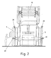
- Figure 2 is a front view of one end of the connection device.
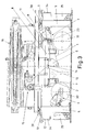
- Figure 3 is a side view of the device connection.
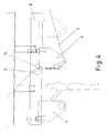
- Figure 4 is a schematic enlarged detail view of the position of the heads of the connection device at the time of the preparation of the new band which will remain in waiting.
- Figure 5 is a schematic enlarged detail view of the position of the heads of the connection device when they are close together and ready for the union of the bands.
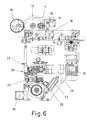
- Figure 6 is an enlarged side view of one of the heads of the connecting device.
- Figure 7 is a side view of the two heads of the connection device when separated.
- Figure 8 is a side view of the two heads of the connection device when they are brought together the other .
- Figure 9 is an exploded perspective view of the entire vertical guidance system of one of the reel holders of the connection device.
- Figure 10 is an exploded perspective view of the axis with the arm guides of one of the spool holders.
- Figure 11 is an exploded perspective view of the gripping mechanism of the spool mandrel which is on the arms of the spools of the connection device.
- FIG. 12 is a perspective view of one of the arms of the spool holder of the connection device with a view exploded expulsion mechanism which detaches the mandrel from the coils.
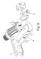
- FIG. 13 is a perspective view of one of the arms of the spool holder of the connection device with a view burst of the braking mechanism which controls the rotation of coils.
- Figure 14 is a perspective view of the structure of mounting of one of the movable elements above spool holders of the connection device.
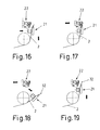
- Figures 15 to 22 are detailed views of the positions successive connection tools during the sequence gluing the final end of the first strip at the start news.
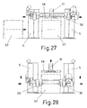
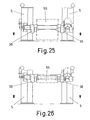
- Figures 23 to 28 show the successive positions the reel loading and replacement sequence on one of the spool holders of the connection device.
- the object of the invention consists of a device for connection which allows to join thin strips (1) and (2) and thus ensuring continuous feeding in the processes where it applies.
- connection device includes two reel holders (3) and (4) which can move vertically and are mounted on load-bearing structures (5) located at the ends of the entire connection device.
- reel holders (3) and (4) are other horizontal structures (9) and (10) along which moving hanging elements (11) and (12) having the form hooks.
- Each of the two heads (6) and (7) is equipped with a motor (17) which allows it to move independently on the structure (8) (cf. fig. 6); these heads (6) and (7) are also equipped with various means (19) which ensure their immobility (6) and (7) when they are close together each other in a central position.
- These heads (6) and (7) also include groups (20) allowing to join the bands (1) and (2) which must be connected.
- These groups (20) are identical for both heads (6) and (7) and each of them comprises two sets independent (21) and (22) of which the first (21) can switch one cylinder (23) while the other can be pushed forward by means of another cylinder (24).
- the tiltable assembly (21) has a fixed front element and an element which is pushed towards it by a cylinder (25) while in the pusher assembly (22) is housed, in a front groove, a retractable knife that can move longitudinally.
- the reel holders (3) and (4) are mounted on guides (26) by means of a carriage (27) which moves by sliding along these guides (26) (cf. fig. 9); the movement of the carriage (27) is caused by a mechanism transmission included in the guides (26) and actuated by motors (28) as can be seen in Figures 2 and 3. In this way each of the reel holders (3) and (4) can be move independently either vertically or along load-bearing structures (5).
- the assembly (21) is then tilted upwards and, simultaneously, the movable element of this assembly (21) so that the strip (2) is pinched between this mobile element and the fixed element opposite it (cf. Fig. 16).
- the assembly (22) of this group (20) then moves towards the front holding the end of the strip (2) captive in the pinching against the fixed element of the assembly (21) as the shows figure (17); the knife of the assembly (22) cuts then the end of the strip (2) along a straight line perfect.
- the assembly (21) is then tilted again towards the top (see fig. 19) and the assembly (22) moves a new times forward until pressing against the fixed element of the assembly (21) the strip (2) while, simultaneously, the entire head (7) moves towards the head (6) to position itself against the latter (cf. fig. 20).
- the strip (2) is glued to the strip (1) by the adhesive strip (32) and the knife of the assembly (22) of the group (20) of the head (6) cuts the strip (1) so that its edge corresponds to the free edge of the strip (2) which ensures perfect continuity between the bands (1) and (2) which are connected end to end by the adhesive strip (32).
- the belt (1) must stop for a moment in the connection area; it is for this reason that the speed of the group motor (15) which governs the supply is variable so that by lowering it to 100 - 150 meters per second the normal feed speed of 650 meters per second when the supply coil (29) is almost empty and the strip (1) separates from it, a total stop of the band (1) occurs (see fig. 21) during which the band necessary for the continuation of the process is extracted from the store (16).
- the roller mobile (14) comes close enough to the fixed roller (13) (cf. Fig. 21) to compress and brake the strip (1).
- the mandrel is removed from the empty spool (29) automatically thanks to the hook-shaped element (11) the structure (9) which is located above; this element (11) is moves on the structure (9) until it hooks the empty reel core (29); he then extracts this mandrel from the reel holder (3) and takes it to the fixed element (34) which has a ramp at the bottom which forces the mandrel to fall from the element (11) to be collected in the container (35) which is located below.
- the operation is identical when the coil (30) which is on the spool holder (4) on the other side, except that the mandrel is removed by the element (12).
- Each of the reel holders (3) and (4) comprises two arms (36) parallel and face to face that can be seen on the figures (12) and (13) and which are fixed by means of a coupling (37) with sliding mounting on an axis (38) provided with guides (39), this arrangement being presented in FIG. 10; these two arms (36) can move along the axis (38) and so get closer or separate from each other under the action motors (40) shown in Figure 2.
- Each arm (36) includes a cone (41) which fits into the corresponding end of the spool of the tape reels (1 or 2) ; this cone (41) in turn includes the mechanism described Figure 11 which includes a cylinder (42) having a rod (43) which penetrates axially into the cone (41) and enters contact with elements (44) which can extend radially through the windows (45) of the cone (41) and carry pads (46); the elements (44) slide on the rod (43) thanks to the guides inclined (47) so that when the rod advances, the elements 44 exit through the windows (45) of the cone (41) and retract when the rod moves back.
- this cone (41) in turn includes the mechanism described Figure 11 which includes a cylinder (42) having a rod (43) which penetrates axially into the cone (41) and enters contact with elements (44) which can extend radially through the windows (45) of the cone (41) and carry pads (46); the elements (44) slide on the rod (43) thanks to the guides inclined (47) so that when the rod advances, the elements 44 exit through the windows (45) of the cone
- a pusher device (50) which acts through cylinders (51) as can be seen on Figure 12; this pusher device (50) pushes the casing (49) forwards to force the spool core to come out of the cone (41) during the removal operation; the housing (49) is returned to the rear position by the proper push said of the mandrel when the arms (36) approach during of the assembly operation.
- each arm (36) includes a braking mechanism (52) which acts on the rotating part of the cone (41) and thanks to which it is possible to control the speed of rotation of the coils installed on the reel holders so as to cancel the inertia and adapt this rotational speed at the unwinding speed of the bandaged.
- a braking mechanism (52) which acts on the rotating part of the cone (41) and thanks to which it is possible to control the speed of rotation of the coils installed on the reel holders so as to cancel the inertia and adapt this rotational speed at the unwinding speed of the bandaged.
- Figure (14) shows in detail the structure (9) of mounting of the hook-shaped element (11) of one of the parts the connection device; you can see the cart (53) on which is mounted the element (11) and the motor (54) which controls its movement. It is obvious that the structure (10) on the other side, on which the element (12) is mounted is identical but in reverse position.
- Coil loading and replacement process on the reel holders (3) and (4) of the connection device is also automatic as shown by the sequence of Figures 23 to 28; to install a coil (55) on a coil holder, the whole of the latter moves on the structures corresponding load-bearing structures (5) to the upper position (see fig. 23), thus allowing the coil (55) to be brought below.
- the spool pin then rises enough for the coil (55) can rotate freely on itself as the shows figure 25; the coil (55) is therefore ready for supply the connection device.
Landscapes
- Replacement Of Web Rolls (AREA)
- Winding, Rewinding, Material Storage Devices (AREA)
Abstract
Description
Claims (9)
- Dispositif de raccordement des bandes minces de bobines d'alimentation du type de ceux qui comprennent deux porte-bobines (3) et (4), l'un supportant la bobine d'alimentation (29) et l'autre la bobine (30) qui la remplacera lorsqu'elle se videra étant ainsi assurée la continuité de l'alimentation ; ce type inclut aussi deux têtes (6) et (7) par où passent les bandes (1) et (2) de chacune des deux bobines ; ces têtes (6) et (7) sont munies de moyens assurant automatiquement l'union des deux bandes (1) et (2) ; ce dispositif se caractérise en ce que les porte-bobines (3) et (4) sont montés sur des structures (5) permettant leur déplacement vertical et qui se trouvent à chaque extrémité du dispositif de raccordement alors que les têtes (6) et (7) sont montées sur une structure horizontale (8) qui se trouve au-dessus de la zone intermédiaire et le long de laquelle elles peuvent se déplacer pour se rapprocher ou se séparer en allant au-dessus des porte-bobines (3) et (4) ; il se caractérise aussi par les structures horizontales (9) et (10) le long desquelles peuvent se déplacer des éléments suspendus (11) et (12) en forme de crochet.
- Dispositif de raccordement des bandes minces de bobines d'alimentation conformément à la première revendication caractérisé en ce que les têtes (6) et (7) peuvent se déplacer sur la structure (8) grâce à un moteur et comprennent des moyens (18) et (19) qui peuvent les bloquer temporairement sur ladite structure.
- Dispositif de raccordement des bandes minces de bobines d'alimentation conformément à la première revendication caractérisé en ce que les têtes (6) et (7) incluent des groupes (20) de collage des bandes (1) et (2) ; chacun de ces groupes (20) inclut à son tour un ensemble (21) basculable et des éléments qui peuvent se rapprocher ou s'écarter les uns des autres et un ensemble (22) qui peut se déplacer vers l'avant ou l'arrière et comporte des outils de coupe qui se trouvent sur sa face frontale.
- Dispositif de raccordement des bandes minces de bobines d'alimentation conformément à la première revendication caractérisé en ce que les porte-bobines (3) et (4) sont montés sur des guides verticaux (26) et peuvent se déplacer individuellement grâce aux mécanismes d'actionnement qui sont inclus dans ces guides.
- Dispositif de raccordement des bandes minces de bobines d'alimentation conformément à la première revendication caractérisé en ce que les porte-bobines (3) et (4) comprennent deux bras (36) parallèles et opposés, montés sur un axe (38) et qui peuvent se déplacer pour se rapprocher ou s'écarter l'un de l'autre ; ces bras (36) incorporent des cônes qui permettent de saisir les bobines à supporter ; ces cônes (41) sont associés à un cylindre (42) à l'intérieur et selon l'axe duquel une tige (43) peut se déplacer et, grâce à des guides inclinés (47), agir sur des éléments (44) qui peuvent sortir ou s'escamoter radialement du cylindre.
- Dispositif de raccordement des bandes minces de bobines d'alimentation conformément à la cinquième revendication caractérisé en ce que le cylindre (42) des cônes (41) comprend un carter (49) mobile selon son axe sur lequel agit un dispositif pousseur (50) monté sur le bras (36) et comprenant des cylindres pousseurs (51).
- Dispositif de raccordement des bandes minces des bobines d'alimentation conformément à la cinquième revendication caractérisé en ce que chaque bras (36) incorpore un mécanisme de freinage (52) qui agit sur l'ensemble tournant du cône (41) pour contrôler la vitesse de rotation des bobines et la tension de la bande de papier.
- Dispositif de raccordement des bandes minces de bobines d'alimentation conformément à la première revendication caractérisé en ce que les structures (9) et (10) sur lesquelles se déplacent les éléments suspendus en forme de crochet (11) et (12) , comportent à leur extrémité un élément fixe (34) en forme de rampe qui se trouve à la hauteur du crochet de l'élément mobile (11) ou (12) et grâce auquel le mandrin se détache du porte-bobine et peut être déposé dans un conteneur (35).
- Dispositif de raccordement des bandes minces de bobines d'alimentation conformément à la première revendication caractérisé en ce que, au-dessus de la position centrale dans laquelle les têtes (6) et (7) sont rapprochées l'une de l'autre , se trouvent deux rouleaux parallèles (13) et (14) qui laissent entre eux un espace par où passe la bande qui alimente le groupe moteur (15) ; un de ces rouleaux (13) dont la position est fixe tourne librement sur son axe alors que le second (14), qui ne tourne pas, peut se déplacer pour se rapprocher ou s'éloigner du premier de façon à presser contre lui la bande d'alimentation.
Applications Claiming Priority (2)
| Application Number | Priority Date | Filing Date | Title |
|---|---|---|---|
| ES200002233 | 2000-09-12 | ||
| ES200002233A ES2183689B1 (es) | 2000-09-12 | 2000-09-12 | Empalmador automatico de bandas laminares procedentes de bobinas de alimentacion. |
Publications (2)
| Publication Number | Publication Date |
|---|---|
| EP1193200A1 true EP1193200A1 (fr) | 2002-04-03 |
| EP1193200B1 EP1193200B1 (fr) | 2004-11-24 |
Family
ID=8494916
Family Applications (1)
| Application Number | Title | Priority Date | Filing Date |
|---|---|---|---|
| EP01402345A Expired - Lifetime EP1193200B1 (fr) | 2000-09-12 | 2001-09-12 | Dispositif automatique de raccordement des bandes minces des bobines d'alimentation |
Country Status (4)
| Country | Link |
|---|---|
| EP (1) | EP1193200B1 (fr) |
| AT (1) | ATE283229T1 (fr) |
| DE (1) | DE60107357T2 (fr) |
| ES (1) | ES2183689B1 (fr) |
Cited By (2)
| Publication number | Priority date | Publication date | Assignee | Title |
|---|---|---|---|---|
| WO2002090228A1 (fr) * | 2001-05-04 | 2002-11-14 | Koenig & Bauer Aktiengesellschaft | Changeur de rouleaux |
| EP2112106A1 (fr) * | 2008-04-24 | 2009-10-28 | MONOMATIC (Société par Actions Simplifiée) | Procédé et dispositif de coupe et de collage bout à bout pour machine à dérouler |
Families Citing this family (1)
| Publication number | Priority date | Publication date | Assignee | Title |
|---|---|---|---|---|
| ES2270674B1 (es) * | 2004-11-04 | 2007-12-01 | Manuel Torres Martinez | Instalacion de desbobinado de papel de tisu con portabobinas basculantes. |
Citations (9)
| Publication number | Priority date | Publication date | Assignee | Title |
|---|---|---|---|---|
| US3381912A (en) * | 1965-11-26 | 1968-05-07 | William F. Huck | Core lockup and sidelay control device for splicing rollstands |
| US3841944A (en) * | 1973-06-26 | 1974-10-15 | Harris Intertype Corp | Web splicing apparatus |
| US4450039A (en) * | 1982-08-23 | 1984-05-22 | Harris Graphics Corporation | Web splicing apparatus |
| US4481053A (en) * | 1981-09-30 | 1984-11-06 | Rengo Co., Ltd. | Method and apparatus for splicing web |
| EP0188795A2 (fr) * | 1985-01-25 | 1986-07-30 | Sms Schloemann-Siemag Aktiengesellschaft | Bobine pour enrouler et/ou dérouler un feuillard |
| FR2618769A1 (fr) * | 1987-07-29 | 1989-02-03 | Monomatic Sa | Machine a derouler des bandes comportant des tours porte-bobines |
| DE4215739A1 (de) * | 1992-05-13 | 1993-11-18 | Kleinewefers Gmbh | Verfahren und Vorrichtung zum Beschicken und Entnehmen von mit einer Materialbahn bewickelten Rollen in einer Maschine zum Verarbeiten der Materialbahn, insbesondere einer Druckmaschine |
| EP0570871A2 (fr) * | 1988-06-18 | 1993-11-24 | Focke & Co. (GmbH & Co.) | Dispositif pour transporter une matière d'emballage dans une machine d'emballage |
| US5762283A (en) * | 1994-01-28 | 1998-06-09 | Stork Contiweb B.V. | Method for preparing the start of a material web of a stock roll in a roll exchanger, roll exchanger and web-takeup device |
Family Cites Families (2)
| Publication number | Priority date | Publication date | Assignee | Title |
|---|---|---|---|---|
| ES411539A1 (es) * | 1973-03-12 | 1976-01-01 | Torres Martinez Gonzalez Telle | Perfeccionamientos en la construccion de maquinas portado- ras de bobinas de papel. |
| US5674049A (en) * | 1994-06-17 | 1997-10-07 | Automatic Handling, Inc. | Roll handling apparatus |
-
2000
- 2000-09-12 ES ES200002233A patent/ES2183689B1/es not_active Expired - Fee Related
-
2001
- 2001-09-12 DE DE60107357T patent/DE60107357T2/de not_active Expired - Lifetime
- 2001-09-12 EP EP01402345A patent/EP1193200B1/fr not_active Expired - Lifetime
- 2001-09-12 AT AT01402345T patent/ATE283229T1/de not_active IP Right Cessation
Patent Citations (9)
| Publication number | Priority date | Publication date | Assignee | Title |
|---|---|---|---|---|
| US3381912A (en) * | 1965-11-26 | 1968-05-07 | William F. Huck | Core lockup and sidelay control device for splicing rollstands |
| US3841944A (en) * | 1973-06-26 | 1974-10-15 | Harris Intertype Corp | Web splicing apparatus |
| US4481053A (en) * | 1981-09-30 | 1984-11-06 | Rengo Co., Ltd. | Method and apparatus for splicing web |
| US4450039A (en) * | 1982-08-23 | 1984-05-22 | Harris Graphics Corporation | Web splicing apparatus |
| EP0188795A2 (fr) * | 1985-01-25 | 1986-07-30 | Sms Schloemann-Siemag Aktiengesellschaft | Bobine pour enrouler et/ou dérouler un feuillard |
| FR2618769A1 (fr) * | 1987-07-29 | 1989-02-03 | Monomatic Sa | Machine a derouler des bandes comportant des tours porte-bobines |
| EP0570871A2 (fr) * | 1988-06-18 | 1993-11-24 | Focke & Co. (GmbH & Co.) | Dispositif pour transporter une matière d'emballage dans une machine d'emballage |
| DE4215739A1 (de) * | 1992-05-13 | 1993-11-18 | Kleinewefers Gmbh | Verfahren und Vorrichtung zum Beschicken und Entnehmen von mit einer Materialbahn bewickelten Rollen in einer Maschine zum Verarbeiten der Materialbahn, insbesondere einer Druckmaschine |
| US5762283A (en) * | 1994-01-28 | 1998-06-09 | Stork Contiweb B.V. | Method for preparing the start of a material web of a stock roll in a roll exchanger, roll exchanger and web-takeup device |
Cited By (5)
| Publication number | Priority date | Publication date | Assignee | Title |
|---|---|---|---|---|
| WO2002090228A1 (fr) * | 2001-05-04 | 2002-11-14 | Koenig & Bauer Aktiengesellschaft | Changeur de rouleaux |
| EP1477443A1 (fr) * | 2001-05-04 | 2004-11-17 | Koenig & Bauer Aktiengesellschaft | Changeur de rouleaux |
| EP2112106A1 (fr) * | 2008-04-24 | 2009-10-28 | MONOMATIC (Société par Actions Simplifiée) | Procédé et dispositif de coupe et de collage bout à bout pour machine à dérouler |
| FR2930534A1 (fr) * | 2008-04-24 | 2009-10-30 | Monimatic Soc Par Actions Simp | Procede et dispositif de coupe et de collage bout a bout pour machine a derouler |
| US8628038B2 (en) | 2008-04-24 | 2014-01-14 | Monomatic | Method and device for cutting and adhesion for an unrolling machine |
Also Published As
| Publication number | Publication date |
|---|---|
| DE60107357T2 (de) | 2006-03-02 |
| DE60107357D1 (de) | 2004-12-30 |
| ES2183689B1 (es) | 2004-02-01 |
| ES2183689A1 (es) | 2003-03-16 |
| ATE283229T1 (de) | 2004-12-15 |
| EP1193200B1 (fr) | 2004-11-24 |
Similar Documents
| Publication | Publication Date | Title |
|---|---|---|
| EP3248920B1 (fr) | Procédé de coupe et de raccordement de deux bandes bout à bout et à l arrêt dans une machine à dérouler, dispositif de coupe et de raccordement et machine équipée d'un tel dispositif permettant la mise en oeuvre dudit procédé | |
| BE1008166A5 (fr) | Bobineuse de bande a tubulure d'injection d'air. | |
| FR2623176A1 (fr) | Appareillage et procede pour traiter la partie d'extremite d'une feuille de papier en rouleau disposee en un emplacement de raccordement | |
| FR2616751A1 (fr) | Machine de sanglage de paquet | |
| EP2112106B1 (fr) | Procédé et dispositif de coupe et de collage bout à bout pour machine à dérouler | |
| FR2484979A1 (fr) | Procede et appareil d'assemblage de matiere en feuille, notamment pour alimenter en continu des imprimantes rapides | |
| FR2538361A1 (fr) | Bobinoir continu pour nappes larges | |
| EP0037343B1 (fr) | Procédé de réalisation d'une liasse apte à la formation d'au moins un classeur à soufflet, et machine pour la mise en oeuvre d'un tel procédé | |
| FR2765191A1 (fr) | Procede et machine de collage automatique d'un film plastique thermoretractable sur le fond d'une caisse ouverte | |
| EP1193200B1 (fr) | Dispositif automatique de raccordement des bandes minces des bobines d'alimentation | |
| FR2503683A1 (fr) | Dispositif de devidage automatique d'une bande d'etoffe provenant d'un rouleau monte sur un support multiple | |
| EP0795504B1 (fr) | Machine à dérouler des bobines en continu comportant au moins un moyen de déroulage de deux bobines jumelées ou coaxiales simultanément | |
| EP0921074B1 (fr) | Procédé et installation pour rassembler des articles alignés au moyen de bandes adhésives | |
| EP0057144A2 (fr) | Machine à emballer des objets de forme sensiblement cylindrique dans des feuilles découpées selon un contour fermé dans des bandes d'un matériau souple d'emballage | |
| EP0337039A1 (fr) | Machine pour la manutention d'articles plats, notamment sacs ou sachets, à la sortie d'une machine de fabrication | |
| EP0206952B1 (fr) | Appareil simplifié de distribution et de coupe simultanées de bandes de matériaux enroulés, avec changement automatique du rouleau en service | |
| FR2515484A1 (fr) | Procede et appareil a enrouler des plaques de pate | |
| EP1315663B1 (fr) | Installation et procede de conditionnement d'une feuille de materiau de moulage | |
| BE889349A (fr) | Procede et appareil d'assemblage de matiere en feuille, notamment pour alimenter en continu des imprimantes rapides | |
| FR2639611A1 (fr) | Dispositif de pose de coiffe sur une charge emballee par banderolage | |
| JPH0597124A (ja) | 製袋充填包装機 | |
| FR2685167A1 (fr) | Procede et dispositif pour charger en garniture et rouler des rouleaux de printemps. | |
| FR2497781A1 (fr) | Procede pour changer les bobines et les mandrins des machines d'enroulement sans axe | |
| FR2613340A1 (fr) | Dispositif de manutention et de montage sur une machine, de bobines de materiaux en bandes | |
| EP0948452B1 (fr) | Procede de formation et de transport de cartouches de cahiers imprimes ainsi que son dispostif de mise en oeuvre |
Legal Events
| Date | Code | Title | Description |
|---|---|---|---|
| PUAI | Public reference made under article 153(3) epc to a published international application that has entered the european phase |
Free format text: ORIGINAL CODE: 0009012 |
|
| AK | Designated contracting states |
Kind code of ref document: A1 Designated state(s): AT BE CH CY DE DK ES FI FR GB GR IE IT LI LU MC NL PT SE TR |
|
| AX | Request for extension of the european patent |
Free format text: AL;LT;LV;MK;RO;SI |
|
| 17P | Request for examination filed |
Effective date: 20020903 |
|
| AKX | Designation fees paid |
Free format text: AT BE CH CY DE DK ES FI FR GB GR IE IT LI LU MC NL PT SE TR |
|
| 17Q | First examination report despatched |
Effective date: 20030414 |
|
| GRAP | Despatch of communication of intention to grant a patent |
Free format text: ORIGINAL CODE: EPIDOSNIGR1 |
|
| RAP1 | Party data changed (applicant data changed or rights of an application transferred) |
Owner name: TORRES MARTINEZ, MANUEL |
|
| RIN1 | Information on inventor provided before grant (corrected) |
Inventor name: TORRES MARTINEZ, MANUEL |
|
| GRAS | Grant fee paid |
Free format text: ORIGINAL CODE: EPIDOSNIGR3 |
|
| GRAA | (expected) grant |
Free format text: ORIGINAL CODE: 0009210 |
|
| AK | Designated contracting states |
Kind code of ref document: B1 Designated state(s): AT BE CH CY DE DK ES FI FR GB GR IE IT LI LU MC NL PT SE TR |
|
| PG25 | Lapsed in a contracting state [announced via postgrant information from national office to epo] |
Ref country code: GB Free format text: LAPSE BECAUSE OF FAILURE TO SUBMIT A TRANSLATION OF THE DESCRIPTION OR TO PAY THE FEE WITHIN THE PRESCRIBED TIME-LIMIT Effective date: 20041124 Ref country code: AT Free format text: LAPSE BECAUSE OF FAILURE TO SUBMIT A TRANSLATION OF THE DESCRIPTION OR TO PAY THE FEE WITHIN THE PRESCRIBED TIME-LIMIT Effective date: 20041124 Ref country code: IE Free format text: LAPSE BECAUSE OF FAILURE TO SUBMIT A TRANSLATION OF THE DESCRIPTION OR TO PAY THE FEE WITHIN THE PRESCRIBED TIME-LIMIT Effective date: 20041124 Ref country code: FI Free format text: LAPSE BECAUSE OF FAILURE TO SUBMIT A TRANSLATION OF THE DESCRIPTION OR TO PAY THE FEE WITHIN THE PRESCRIBED TIME-LIMIT Effective date: 20041124 Ref country code: TR Free format text: LAPSE BECAUSE OF FAILURE TO SUBMIT A TRANSLATION OF THE DESCRIPTION OR TO PAY THE FEE WITHIN THE PRESCRIBED TIME-LIMIT Effective date: 20041124 Ref country code: NL Free format text: LAPSE BECAUSE OF FAILURE TO SUBMIT A TRANSLATION OF THE DESCRIPTION OR TO PAY THE FEE WITHIN THE PRESCRIBED TIME-LIMIT Effective date: 20041124 |
|
| REG | Reference to a national code |
Ref country code: GB Ref legal event code: FG4D Free format text: NOT ENGLISH |
|
| REG | Reference to a national code |
Ref country code: CH Ref legal event code: EP |
|
| REF | Corresponds to: |
Ref document number: 60107357 Country of ref document: DE Date of ref document: 20041230 Kind code of ref document: P |
|
| REG | Reference to a national code |
Ref country code: IE Ref legal event code: FG4D Free format text: FRENCH |
|
| PG25 | Lapsed in a contracting state [announced via postgrant information from national office to epo] |
Ref country code: SE Free format text: LAPSE BECAUSE OF FAILURE TO SUBMIT A TRANSLATION OF THE DESCRIPTION OR TO PAY THE FEE WITHIN THE PRESCRIBED TIME-LIMIT Effective date: 20050224 Ref country code: DK Free format text: LAPSE BECAUSE OF FAILURE TO SUBMIT A TRANSLATION OF THE DESCRIPTION OR TO PAY THE FEE WITHIN THE PRESCRIBED TIME-LIMIT Effective date: 20050224 Ref country code: GR Free format text: LAPSE BECAUSE OF FAILURE TO SUBMIT A TRANSLATION OF THE DESCRIPTION OR TO PAY THE FEE WITHIN THE PRESCRIBED TIME-LIMIT Effective date: 20050224 |
|
| PG25 | Lapsed in a contracting state [announced via postgrant information from national office to epo] |
Ref country code: ES Free format text: LAPSE BECAUSE OF FAILURE TO SUBMIT A TRANSLATION OF THE DESCRIPTION OR TO PAY THE FEE WITHIN THE PRESCRIBED TIME-LIMIT Effective date: 20050306 |
|
| NLV1 | Nl: lapsed or annulled due to failure to fulfill the requirements of art. 29p and 29m of the patents act | ||
| GBV | Gb: ep patent (uk) treated as always having been void in accordance with gb section 77(7)/1977 [no translation filed] |
Effective date: 20041124 |
|
| REG | Reference to a national code |
Ref country code: IE Ref legal event code: FD4D |
|
| PG25 | Lapsed in a contracting state [announced via postgrant information from national office to epo] |
Ref country code: CY Free format text: LAPSE BECAUSE OF FAILURE TO SUBMIT A TRANSLATION OF THE DESCRIPTION OR TO PAY THE FEE WITHIN THE PRESCRIBED TIME-LIMIT Effective date: 20050912 |
|
| PG25 | Lapsed in a contracting state [announced via postgrant information from national office to epo] |
Ref country code: MC Free format text: LAPSE BECAUSE OF NON-PAYMENT OF DUE FEES Effective date: 20050930 Ref country code: CH Free format text: LAPSE BECAUSE OF NON-PAYMENT OF DUE FEES Effective date: 20050930 Ref country code: BE Free format text: LAPSE BECAUSE OF NON-PAYMENT OF DUE FEES Effective date: 20050930 Ref country code: LI Free format text: LAPSE BECAUSE OF NON-PAYMENT OF DUE FEES Effective date: 20050930 Ref country code: LU Free format text: LAPSE BECAUSE OF NON-PAYMENT OF DUE FEES Effective date: 20050930 |
|
| PLBE | No opposition filed within time limit |
Free format text: ORIGINAL CODE: 0009261 |
|
| STAA | Information on the status of an ep patent application or granted ep patent |
Free format text: STATUS: NO OPPOSITION FILED WITHIN TIME LIMIT |
|
| 26N | No opposition filed |
Effective date: 20050825 |
|
| REG | Reference to a national code |
Ref country code: CH Ref legal event code: PL |
|
| BERE | Be: lapsed |
Owner name: *TORRES MARTINEZ MANUEL Effective date: 20050930 |
|
| PG25 | Lapsed in a contracting state [announced via postgrant information from national office to epo] |
Ref country code: PT Free format text: LAPSE BECAUSE OF NON-PAYMENT OF DUE FEES Effective date: 20050424 |
|
| PGFP | Annual fee paid to national office [announced via postgrant information from national office to epo] |
Ref country code: DE Payment date: 20120920 Year of fee payment: 12 Ref country code: FR Payment date: 20120927 Year of fee payment: 12 Ref country code: IT Payment date: 20120920 Year of fee payment: 12 |
|
| REG | Reference to a national code |
Ref country code: DE Ref legal event code: R119 Ref document number: 60107357 Country of ref document: DE Effective date: 20140401 |
|
| REG | Reference to a national code |
Ref country code: FR Ref legal event code: ST Effective date: 20140530 |
|
| PG25 | Lapsed in a contracting state [announced via postgrant information from national office to epo] |
Ref country code: IT Free format text: LAPSE BECAUSE OF NON-PAYMENT OF DUE FEES Effective date: 20130912 Ref country code: DE Free format text: LAPSE BECAUSE OF NON-PAYMENT OF DUE FEES Effective date: 20140401 Ref country code: FR Free format text: LAPSE BECAUSE OF NON-PAYMENT OF DUE FEES Effective date: 20130930 |