EP1193366A2 - Procédé et dispositif de prévision des paramètres de forage utilisant un réseau neuronal - Google Patents
Procédé et dispositif de prévision des paramètres de forage utilisant un réseau neuronal Download PDFInfo
- Publication number
- EP1193366A2 EP1193366A2 EP01308364A EP01308364A EP1193366A2 EP 1193366 A2 EP1193366 A2 EP 1193366A2 EP 01308364 A EP01308364 A EP 01308364A EP 01308364 A EP01308364 A EP 01308364A EP 1193366 A2 EP1193366 A2 EP 1193366A2
- Authority
- EP
- European Patent Office
- Prior art keywords
- sensors
- drilling
- bha
- parameters
- neural network
- Prior art date
- Legal status (The legal status is an assumption and is not a legal conclusion. Google has not performed a legal analysis and makes no representation as to the accuracy of the status listed.)
- Withdrawn
Links
- 238000005553 drilling Methods 0.000 title claims abstract description 178
- 238000013528 artificial neural network Methods 0.000 title claims abstract description 66
- 238000000034 method Methods 0.000 title claims description 51
- 230000000694 effects Effects 0.000 claims abstract description 9
- 239000012530 fluid Substances 0.000 claims description 35
- 230000004064 dysfunction Effects 0.000 claims description 28
- 230000015572 biosynthetic process Effects 0.000 claims description 26
- 238000005259 measurement Methods 0.000 claims description 20
- 230000008569 process Effects 0.000 claims description 12
- 230000008859 change Effects 0.000 claims description 9
- 238000011156 evaluation Methods 0.000 claims description 8
- 239000000126 substance Substances 0.000 claims description 8
- 238000012545 processing Methods 0.000 claims description 5
- 230000004044 response Effects 0.000 claims description 4
- 230000000704 physical effect Effects 0.000 claims 3
- 238000012937 correction Methods 0.000 abstract description 4
- 238000005755 formation reaction Methods 0.000 description 23
- 230000006399 behavior Effects 0.000 description 19
- 230000006870 function Effects 0.000 description 11
- 238000012549 training Methods 0.000 description 11
- 210000002569 neuron Anatomy 0.000 description 9
- 230000009471 action Effects 0.000 description 8
- 230000005251 gamma ray Effects 0.000 description 7
- 239000013598 vector Substances 0.000 description 7
- 238000010586 diagram Methods 0.000 description 6
- 238000012360 testing method Methods 0.000 description 6
- 230000004913 activation Effects 0.000 description 5
- 230000035515 penetration Effects 0.000 description 5
- 238000013459 approach Methods 0.000 description 4
- 238000011161 development Methods 0.000 description 4
- 238000012986 modification Methods 0.000 description 4
- 230000004048 modification Effects 0.000 description 4
- 238000005457 optimization Methods 0.000 description 4
- 230000000712 assembly Effects 0.000 description 3
- 238000000429 assembly Methods 0.000 description 3
- 238000005520 cutting process Methods 0.000 description 3
- 230000036541 health Effects 0.000 description 3
- 230000008439 repair process Effects 0.000 description 3
- 239000011435 rock Substances 0.000 description 3
- 238000005452 bending Methods 0.000 description 2
- 239000003086 colorant Substances 0.000 description 2
- 238000006073 displacement reaction Methods 0.000 description 2
- 230000003993 interaction Effects 0.000 description 2
- VNWKTOKETHGBQD-UHFFFAOYSA-N methane Chemical compound C VNWKTOKETHGBQD-UHFFFAOYSA-N 0.000 description 2
- 239000000203 mixture Substances 0.000 description 2
- 230000035699 permeability Effects 0.000 description 2
- 230000035939 shock Effects 0.000 description 2
- 239000003381 stabilizer Substances 0.000 description 2
- 230000001133 acceleration Effects 0.000 description 1
- 238000013473 artificial intelligence Methods 0.000 description 1
- 230000015556 catabolic process Effects 0.000 description 1
- 238000004883 computer application Methods 0.000 description 1
- 230000003247 decreasing effect Effects 0.000 description 1
- 238000006731 degradation reaction Methods 0.000 description 1
- 230000001627 detrimental effect Effects 0.000 description 1
- 238000005516 engineering process Methods 0.000 description 1
- 238000004880 explosion Methods 0.000 description 1
- 238000012625 in-situ measurement Methods 0.000 description 1
- 238000002347 injection Methods 0.000 description 1
- 239000007924 injection Substances 0.000 description 1
- 238000013507 mapping Methods 0.000 description 1
- 239000011159 matrix material Substances 0.000 description 1
- 238000012544 monitoring process Methods 0.000 description 1
- 238000003062 neural network model Methods 0.000 description 1
- 230000000737 periodic effect Effects 0.000 description 1
- 230000002093 peripheral effect Effects 0.000 description 1
- 238000007781 pre-processing Methods 0.000 description 1
- 230000002028 premature Effects 0.000 description 1
- 238000004088 simulation Methods 0.000 description 1
- 230000006641 stabilisation Effects 0.000 description 1
- 238000011105 stabilization Methods 0.000 description 1
- 230000000087 stabilizing effect Effects 0.000 description 1
- 230000003068 static effect Effects 0.000 description 1
- 239000013589 supplement Substances 0.000 description 1
- 238000012546 transfer Methods 0.000 description 1
- 230000000007 visual effect Effects 0.000 description 1
- XLYOFNOQVPJJNP-UHFFFAOYSA-N water Substances O XLYOFNOQVPJJNP-UHFFFAOYSA-N 0.000 description 1
Images



Classifications
-
- E—FIXED CONSTRUCTIONS
- E21—EARTH OR ROCK DRILLING; MINING
- E21B—EARTH OR ROCK DRILLING; OBTAINING OIL, GAS, WATER, SOLUBLE OR MELTABLE MATERIALS OR A SLURRY OF MINERALS FROM WELLS
- E21B44/00—Automatic control systems specially adapted for drilling operations, i.e. self-operating systems which function to carry out or modify a drilling operation without intervention of a human operator, e.g. computer-controlled drilling systems; Systems specially adapted for monitoring a plurality of drilling variables or conditions
- E21B44/005—Below-ground automatic control systems
-
- E—FIXED CONSTRUCTIONS
- E21—EARTH OR ROCK DRILLING; MINING
- E21B—EARTH OR ROCK DRILLING; OBTAINING OIL, GAS, WATER, SOLUBLE OR MELTABLE MATERIALS OR A SLURRY OF MINERALS FROM WELLS
- E21B2200/00—Special features related to earth drilling for obtaining oil, gas or water
- E21B2200/22—Fuzzy logic, artificial intelligence, neural networks or the like
Definitions
- This invention relates generally to systems for drilling oilfield wellbores and more particularly to the use of a neural network to model dynamic behavior of a non-linear multi-input drilling system.
- Oilfield wellbores are formed by rotating a drill bit carried at an end of an assembly commonly referred to as the bottom hole assembly or "BHA.”
- BHA bottom hole assembly
- the BHA is conveyed into the wellbore by a drill pipe or coiled-tubing.
- the rotation of the drill bit is effected by rotating the drill pipe and/or by a mud motor depending upon the tubing used.
- BHA is used to mean a bottom hole assembly with or without the drill bit.
- Prior art bottom hole assemblies generally include one or more formation evaluation sensors, such as sensors for measuring the resistivity, porosity and density of the formation.
- Such bottom hole assemblies also include devices to determine the BHA inclination and azimuth, pressure sensors, temperature sensors, gamma ray devices, and devices that aid in orienting the drill bit a particular direction and to change the drilling direction.
- Acoustic and resistivity devices have been proposed for determining bed boundaries around and in some cases in front of the drill bit.
- the operating or useful life of the drill bit, mud motor, bearing assembly, and other elements of the BHA depends upon the manner in which such devices are operated and the downhole conditions. This includes rock type, drilling conditions such as pressure, temperature, differential pressure across the mud motor, rotational speed, torque, vibration, drilling fluid flow rate, force on the drill bit or the weight-on-bit ("WOB”), type of the drilling fluid used and the condition of the radial and axial bearings.
- drilling conditions such as pressure, temperature, differential pressure across the mud motor, rotational speed, torque, vibration, drilling fluid flow rate, force on the drill bit or the weight-on-bit (“WOB”), type of the drilling fluid used and the condition of the radial and axial bearings.
- WOB weight-on-bit
- Physical and chemical properties of the drilling fluid near the drill bit can be significantly different from those at the surface. Currently, such properties are usually measured at the surface, which are then used to estimate the properties downhole. Fluid proerties, such as the viscosity, density, clarity, pH level, temperature and pressure profile can significantly affect the drilling efficiency. Downhole measured drilling fluid properties can provide useful information about the actual drilling conditions near the drill bit.
- MWD downhole vibration Measurement-While-Drilling
- a multi-sensor downhole MWD tool acquires and processes dynamic measurement, and generates diagnostic parameters, which quantify the vibration related drilled dysfunction. These diagnostics are then immediately transmitted to the surface via MWD telemetry.
- the transmitted information may be presented to the driller in a very simple form, (for example, as green-yellow-red traffic lights or color bars) using a display on the rig floor. Recommended corrective actions are presented alongside the transmitted diagnostics. Based on this information, and using his own experience, the driller can then modify the relevant control parameters (such as hook load, drill string RPM and mud flow rate) to avoid or resolve a drilling problem.
- the driller After modifying the control parameters, and after the next portion of downhole data is received at the surface, the driller observes the results of the corrective actions using the rig floor display. If necessary, the driller might again modify the surface controls. This process may tentatively continue until the desired drilling mode is achieved.
- Drilling dynamic simulators have been developed based on a pseudo-statistical approach.
- a system identification technique was used to implement this concept. This approach requires the acquisition of downhole and surface drilling dynamics data, along with values of the surface control parameters, over significant intervals of time. This information is then used to create a model that, to some degree, simulates the behavior of the real drilling system.
- This approach represented a significant step forward in predictive drilling dynamics modeling, it achieved only limited success, as it was appropriate only for the identification of linear systems.
- the behavior of a drilling system can be significantly non-linear. Therefore other methods of modeling the dynamic behavior of the drilling system to achieve the necessary degree of predictive accuracy are desirable.
- Real-time monitoring of BHA and drill bit dynamic behavior is a critical factor in improving drilling efficiency. It allows the driller to avoid detrimental drillstring vibrations and maintain optimum drilling conditions through periodic adjustments to various surface control parameters (such as hook load, RPM, flow rate and mud properties).
- surface control parameters such as hook load, RPM, flow rate and mud properties.
- selection of the correct control parameters is not a trivial task. A few iterations in parameter modification may be required before the desired effect is achieved and, even then, further modification may be necessary. For this reason, the development of efficient methods to predict the dynamic behavior of the BHA and methods to select the appropriate control parameters is important for improving drilling efficiency.
- the present invention addresses the above noted problems and provides a drilling apparatus that utilizes a Neural Network (NN) to monitor physical parameters relating to various elements in the drilling apparatus BHA including drill bit wear, temperature, mud motor rpm, torque, differential pressure across the mud motor, stator temperature, bearing assembly temperature, radial and axial displacement, oil level in the case of sealed-bearing-type bearing assemblies, and weight-on-bit (WOB).
- NN Neural Network
- the present invention provides an apparatus and method for automated drilling operations using predictive control.
- the apparatus includes a drill bit disposed on a distal end of a drillstring.
- a plurality of sensors are disposed in the drillstring for making measurements during the drilling of the wellbore relating to a parameter of interest.
- a processor is associated with the sensors to process the measurements for creating answers indicative of the measured parameter of interest, and a downhole analyzer including a neural network is operatively associated with the sensors and the processor for predicting behavior of the drillstring.
- Sensors in the plurality of sensors are selected from drill bit sensors, sensors which provide parameters for a mud motor, BHA condition sensors, BHA position and direction sensors, borehole condition sensors, an rpm sensor, a weight on bit sensor, formation evaluation sensors, seismic sensors, sensors for of a fluid in the wellbore, and sensors that measure chemical properties of the wellbore fluid.
- sensors, the analyzer neural network and processor cooperate to develop recommendations for future drilling parameter settings based in part on the measured parameters and in part on one or more what-if scenarios.
- a method includes drilling a wellbore using a drill bit disposed on a distal end of a drillstring, making measurements during the drilling of the wellbore relating to a parameter of interest using a plurality of sensors disposed in the drillstring, and processing the measurements with a processor. Behavior of the drillstring is then predicted using a downhole analyzer that includes a neural network operatively associated with the sensors and the processor.
- the method includes predicting future behavior based on measured parameters and one or more what-if scenarios.
- the predicted behavior is then used to develop recommendations for future drilling operation parameters.
- the recommendations may be implemented by operation interaction with an interface panel, or the recommendations may be implemented autonomously within the drilling tool.
- the system of the present invention achieves drilling at enhanced drilling rates and with extended component life.
- the system utilizes a BHA having a plurality of sensors for measuring parameters of interest relating to the drilling operation.
- the measured parameters are analyzed using a neural network for predicting future behavior of the drilling system.
- Recommendations for changing one or more drilling parameters are provided via an interface panel and the driller may effect changes using the recommendations or the driller may allow the system to autonomously effect the changes.
- the present invention provides a drilling system for drilling oilfield boreholes or wellbores.
- An important feature of this invention is the use of neural network algorithms and an integrated bottom hole assembly ("BHA") (also referred to herein as the drilling assembly) for use in drilling wellbores.
- BHA bottom hole assembly
- a suitable tool which may be adapted for use in the present invention, is described in U.S. Patent No. 6,233,524 issued on May 15, 2001 and having a common assignee with the present invention, the entire contents of which are incorporated herein by reference.
- Another suitable tool having an integrated BHA, which may be adapted for use in the present invention is described in U.S. Patent No. 6,206,108 issued on March 27, 2001 and having a common assignee with the present invention, the entire contents of which are incorporated herein by reference.
- Neural Network methodology is a modeling technique. In the present invention, this methodology is used to develop a real world on-line advisor for the driller in a closed loop drilling control system. The method provides the driller with a quantitative recommendation on how to modify key drilling control parameters. The following section examines certain theoretical aspects of the application of Neural Networks to predictive control of drilling dynamics.
- Neural Networks demonstrate many desirable properties required in situations with complex, nonlinear and uncertain control parameters. Some of these properties which make Neural Networks suitable for intelligent control applications, include learning by experience ("human-like” learning behavior); ability to generalize (map similar inputs to similar outputs); parallel distributed process for fast processing of large scale dynamic systems; robustness in the presence of noise; and multivariable capabilities.
- the basic processing element of NN is often called a neuron.
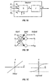
- Each neuron has multiple inputs and a single output as shown in Fig. 1A.
- Some activation functions are presented in Fig. 1C. These functions, as shown, may be linear or sigmoid.
- a layer is not constrained to having the number of its inputs equal to the number of its neurons.
- a network can have several layers. Each layer has a weight matrix W, a bias vector b and an output vector a. The output from each intermediate layer is the input to the following layer.
- the layers in a multi-layer network play different roles. A layer that produces the network output is called an output layer. All other layers are called hidden layers.
- the network shown in Fig. 4, for example, has one output layer and two hidden layers.
- Training procedures may be applied once topology and activation functions are defined.
- supervised learning a set of input data and correct output data (targets) are used to train the network.
- the network using the set of training input, produces its own output. This output is compared with the targets and the differences are used to modify the weights and biases.
- Methods of deriving the changes that might be made in a network, or a procedure for modifying the weights and biases of a network, are called learning rules.
- test set i.e. a set of inputs and targets that were not used in training the network, is used to verify the quality of the obtained NN.
- the test set is used to verify how well the NN can generalize.
- Generalization is an attribute of a network whose output for a new input vector tends to be close to the output generated for similar input vectors in its training set.
- a BHA may include a number of sensors, downhole controllable devices, processing circuits and a neural network algorithm.
- the BHA carries the drill bit and is conveyed into the wellbore by a drill pipe or a coiled-tubing.
- the BHA utilizing the NN and/or information provided from the surface processes sensor measurements, tests and calibrates the BHA components, computes parameters of interest that relate to the condition or health of the BHA components, computes formation parameters, borehole parameters, parameters relating to the drilling fluid, bed boundary information, and in response thereto determines the desired drilling parameters.
- the BHA might also take actions downhole by automatically controlling or adjusting downhole controllable devices to optimize the drilling effectiveness.
- the BHA includes sensors for determining parameters relating to the physical condition or health of the various components of the BHA, such as the drill bit wear, differential pressure across the mud motor, degradation of the mud motor stator, oil leaks in the bearing assembly, pressure and temperature profiles of the BHA and the drilling fluid, vibration, axial and radial displacement of the bearing assembly, whirl, torque and other physical parameters.
- Such parameters are generally referred to herein as the "BHA parameters” or "BHA health parameters.”
- Formation evaluation sensors included in the BHA provide characteristics of the formations surrounding the BHA. Such parameters include the formation resistivity, dielectric constant, formation porosity, formation density, formation permeability, formation acoustic velocity, rock composition, lithological characteristics of the formation and other formation related parameters. Such parameters are generally referred to herein as the "formation evaluation parameters.” Any other sensor suitable for drilling operations is considered within the scope of the present invention.
- the fluid parameters sensors include sensors for determining the temperature and pressure profiles of the wellbore fluid, sensors for determining the viscosity, compressibility, density, chemical composition (gas, water, oil and methane contents, etc.).
- the BHA also contains sensors which determine the position, inclination and direction of the drill bit (collectively referred to herein as the "position” or “directional” parameters); sensors for determining the borehole condition, such as the borehole size, roughness and cracks (collectively referred to as the "borehole parameters”); sensors for determining the locations of the bed boundaries around and ahead of the BHA; and sensors for determining other geophysical parameters (collectively referred to as the “geophysical parameters”).
- the BHA also measures “drilling parameters” or “operations parameters,” which include the drilling fluid flow rate, drill bit rotary speed, torque, and weight-on-bit or the thrust force on the bit (“WOB").
- the BHA contains steering devices that can be activated downhole to alter the drilling direction.
- the BHA also may contain a thruster for applying mechanical force to the drill bit for drilling horizontal wellbores and a jet intensifier for aiding the drill bit in cutting rocks.
- the BHA preferably includes redundant sensors and devices which are activated when their corresponding primary sensors or devices becomes inoperative.
- the neural network algorithms are stored in the BHA memory.
- the NN dynamic model is updated during the drilling operations based on information obtained during such drilling operations. Such updated models are then utilized to further drill the borehole.
- the BHA contains a processor that processes the measurements from the various sensors, communicates with surface computers, and utilizing the NN determines which devices or sensors to operate at any given time. It also computes the optimum combination of the drilling parameters, the desired drilling path or direction, the remaining operating life of certain components of the BHA, the physical and chemical condition of the drilling fluid downhole, and the formation parameters.
- the downhole processor computes the required answers and, due to the limited telemetry capability, transmits to the surface only selected information. The information that is needed for later use is stored in the BHA memory.
- the BHA takes the actions that can be taken downhole. It alters the drilling direction by appropriately operating the direction control devices, adjusts fluid flow through the mud motor to operate it at the determined rotational speed and sends signals to the surface computer, which adjusts the drilling parameters. Additionally, the downhole processor and the surface computer cooperate with each other to manipulate the various types of data utilizing the NN, take actions to achieve in a closed-loop manner more effective drilling of the wellbore, and providing information that is useful for drilling other wellbores.
- Dysfunctions relating to the BHA, the current operating parameters and other downhole-computed operating parameters are provided to the drilling operator, preferably in the form of a display on a screen.
- the system may be programmed to automatically adjust one or more of the drilling parameters to the desired or computed parameters for continued operations.
- the system may also be programmed so that the operator can override the automatic adjustments and manually adjust the drilling parameters within predefined limits for such parameters.
- the system is preferably programmed to provide visual and/or audio alarms and/or to shut down the drilling operation if certain predefined conditions exist during the drilling operations.
- the preferred embodiments of the integrated BHA of the present invention and the operation of the drilling system utilizing such a BHA are described below.
- FIG. 2 shows a schematic diagram of a drilling system 10 having a bottom hole assembly (BHA) or drilling assembly 90 shown conveyed in a borehole 26.
- the drilling system 10 includes a conventional derrick 11 erected on a floor 12 which supports a rotary table 14 that is rotated by a prime mover such as an electric motor (not shown) at a desired rotational speed.
- the drill string 20 includes a tubing (drill pipe or coiled-tubing) 22 extending downward from the surface into the borehole 26.
- a tubing injector 14a is used to inject the BHA into the wellbore when a coiled-tubing is used as the conveying member 22.
- a drill bit 50 attached to the drill string 20 end, disintegrates the geological formations when it is rotated to drill the borehole 26.
- the drill string 20 is coupled to a drawworks 30 via a kelly joint 21, swivel 28 and line 29 through a pulley 27.
- Drawworks 30 is operated to control the weight on bit (“WOB”), which is an important parameter that affects the rate of penetration (“ROP").
- WOB weight on bit
- ROP rate of penetration
- a suitable drilling fluid 31 from a mud pit (source) 32 is circulated under pressure through the drill string 20 by a mud pump 34.
- the drilling fluid passes from the mud pump 34 into the drill string 20 via a desurger 36 and a fluid line 38.
- the drilling fluid 31 discharges at the borehole bottom 51 through openings in the drill bit 50.
- the drilling fluid 31 circulates uphole through the annular space 27 between the drill string 20 and the borehole 26 and returns to the mud pit 32 via a return line 35 and drill cuttings screen 85 that removes drill cuttings 86 from the returning drilling fluid 31b .
- a sensor S1 in line 38 provides information about the fluid flow rate.
- a surface torque sensor S2 and a sensor S3 associated with the drill string 20 respectively provide information about the torque and the rotational speed of the drill string 20 .
- Tubing injection speed is determined from the sensor S5 , while the sensor S6 provides the hook load of the drill string 20.
- the drill bit 50 is rotated by only rotating the drill pipe 22.
- a downhole motor 55 (mud motor) is disposed in the drilling assembly 90 to rotate the drill bit 50 and the drill pipe 22 is rotated usually to supplement the rotational power, if required, and to effect changes in the drilling direction.
- the ROP for a given BHA largely depends upon the WOB or the thrust force on the drill bit 50 and its rotational speed.
- the mud motor 55 is coupled to the drill bit 50 via a drive shaft (not shown) disposed in a bearing assembly 57.
- the mud motor 55 rotates the drill bit 50 when the drilling fluid 31 passes through the mud motor 55 under pressure.
- the bearing assembly 57 supports the radial and axial forces of the drill bit 50, the downthrust of the mud motor 55 and the reactive upward loading from the applied weight on bit.
- a lower stabilizer 58a coupled to the bearing assembly 57 acts as a centralizer for the lowermost portion of the drill string 20.
- a surface control unit or processor 40 receives signals from the downhole sensors and devices via a sensor 43 placed in the fluid line 38 and signals from sensors S1-S6 and other sensors used in the system 10 and processes such signals according to programmed instructions provided to the surface control unit 40.
- the surface control unit 40 displays desired drilling parameters and other information on a display/monitor 42 that is utilized by an operator to control the drilling operations.
- the surface control unit 40 contains a computer, memory for storing data, recorder for recording data and other peripherals.
- the BHA 90 preferably contains a downhole-dynamic-measurement device or "DDM" 59 that contains sensors which make measurements relating to the BHA parameters.
- DDM downhole-dynamic-measurement device
- Such parameters include bit bounce, stick-slip of the BHA, backward rotation, torque, shocks, BHA whirl, BHA buckling, borehole and annulus pressure anomalies and excessive acceleration or stress, and may include other parameters such as BHA and drill bit side forces, and drill motor and drill bit conditions and efficiencies.
- the DDM 59 sensor signals are processed to determine the relative value or severity of each such parameter as a parameter of interest, which are utilized by the BHA and/or the surface computer 40.
- the DDM sensors may be placed in a subassembly or placed individually at any suitable location in the BHA 90.
- Drill bit 50 may contain sensors 51a for determining the drill bit condition and wear.
- the BHA also contains formation evaluation sensors or devices for determining resistivity, density and porosity of the formations surrounding the BHA.
- a gamma ray device for measuring the gamma ray intensity and other nuclear an non-nuclear devices used as measurement-while-drilling devices are suitably included in the BHA 90.
- FIG. 1 shows a resistivity measuring device 64 coupled above a lower kick-off subassembly 62. It provides signals from which resistivity of the formation near or in front of the drill bit 50 is determined.
- An inclinometer 74 and a gamma ray device 76 are suitably placed along the resistivity measuring device 64 for respectively determining the inclination of the portion of the drill string near the drill bit 50 and the formation gamma ray intensity. Any suitable inclinometer and gamma ray device, however, may be utilized for the purposes of this invention.
- position sensors such as accelerometers, magnetometers or a gyroscopic devices may be disposed in the BHA to determine the drill string azimuth, true coordinates and direction in the wellbore 26. Such devices are known in the art and therefore are not described in detail herein.
- the mud motor 55 transfers power to the drill bit 50 via one or more hollow shafts that run through the resistivity measuring device 64.
- the hollow shaft enables the drilling fluid to pass from the mud motor 55 to the drill bit 50.
- the mud motor 55 may be coupled below resistivity measuring device 64 or at any other suitable place.
- the above described resistivity device, gamma ray device and the inclinometer are preferably placed in a common housing that may be coupled to the motor.
- the devices for measuring formation porosity, permeability and density are preferably placed above the mud motor 55. Such devices are known in the art and are thus not described in any detail.
- a large number of the current drilling systems especially for drilling highly deviated and horizontal wellbores, utilize coiled-tubing for conveying the drilling assembly downhole.
- a thruster 71 is deployed in the drill string 90 to provide the required force on the drill bit.
- the term weight on bit is used to denote the force on the bit applied to the drill bit during the drilling operation, whether applied by adjusting the weight of the drill string or by thrusters.
- the tubing is not rotated by a rotary table, instead it is injected into the wellbore by a suitable injector 14a while the downhole motor 55 rotates the drill bit 50.
- a number of sensors are also placed in the various individual devices in the drilling assembly. For example, a variety of sensors are placed in the mud motor power section, bearing assembly, drill shaft, tubing and drill bit to determine the condition of such elements during drilling and to determine the borehole parameters.
- the bottom hole assembly 90 also contains devices which may be activated downhole as a function of the downhole computed parameters of interest alone or in combination with surface transmitted signals to adjust the drilling direction without retrieving the drill string from the borehole, as is commonly done in the prior art. This is achieved in the present invention by utilizing downhole adjustable devices, such as the stabilizers and kick-off assembly, which are well known.
- the description thus far has related to specific examples of the sensors and their placement in the drillstring and BHA, and certain preferred modes of operation of the drilling system.
- This system results in forming wellbores at enhanced drilling rates (rate of penetration) with increased life of drilling components such as the BHA assembly.
- a wellbore can be drilled in a shorter time period by drilling certain portions of the wellbore at relatively slower ROP's because drilling at such ROP's prevents excessive BHA failures, such as motor wear, drill bit wear, sensor failures, thereby allowing greater drilling time between retrievals of the BHA from the wellbore for repairs or replacements.
- the overall configuration of the integrated BHA of the present invention and the operation of the drilling system containing such a BHA is described below.
- Fig. 3 illustrates the application of neural network methodology according to the present invention to simulate and control the dynamic behavior of a drilling system or plant 300.
- the plant 300 is a combination of drilling components such as the rig 302, plant characteristics 304 , media description 306 , and a downhole analyzer 308 . All surface and downhole equipment are represented as the rig 302 , and the method includes consideration of parameters, which influence the performance of the rig 302 .
- Control parameters 310 include all the parameters the driller can control interactively to affect rig output 312 .
- Plant characteristics 304 are the parameters related directly to the drilling equipment. These are predefined and their values are preferably not dynamically modified. Plant characteristics 304 include geometrical and mechanical parameters of the BHA, characteristics of the drill bit and downhole motor (if used), and other technical parameters of the drilling rig and its components. Media description 306 are those parameters which clearly affect rig performance but whose values are either unknown or only known to a certain degree while drilling. Media parameters include formation lithology, mechanical properties of the formation, wellbore geometry and well profile.
- Rig output 312 defines those parameters to be controlled. Examples include rate of penetration (ROP), drillstring and BHA vibration (for example, the lateral, torsional and axial components of vibration), downhole WOB, downhole RPM. ROP is the measurement of on-bottom drilling progress. Downhole vibrations are one of the main causes of drilling problems. Weight-on bit and rotating speed must be controlled due to the technical specifications and limitations of the drilling equipment.
- ROP rate of penetration
- BHA vibration for example, the lateral, torsional and axial components of vibration
- WOB downhole WOB
- RPM downhole RPM
- ROP is the measurement of on-bottom drilling progress.
- Downhole vibrations are one of the main causes of drilling problems. Weight-on bit and rotating speed must be controlled due to the technical specifications and limitations of the drilling equipment.
- a downhole analyzer 308 is used to process sensor output data to determine characteristics such as downhole vibration measurements in a timely manner.
- the downhole analyzer 308 both identifies each of a variety of drilling phenomena and quantifies a severity for each phenomenon. This allows for significantly reducing the volume of data sent to the surface, and provides the driller with condensed information about the most critical downhole dynamic dysfunctions (for example, bit bounce, BHA whirl, bending, and stick-slip).
- the outputs 314 of the analyzer 308 are conveyed to a database 316 and to the driller at the surface.
- a Multilayer Feedforward Neural Network is used, because the MFNN has several desirable properties.
- the MFNN possesses two layers, where a hidden layer is sigmoid and an output layer is linear (see Fig. 1C ), and can be trained to approximately any function (with a finite number of discontinuities) for a given well.
- the MFNN is a static mapping model, and theoretically it is not feasible to control or identify the dynamic system. However, it can be extended to the dynamic domain 400 as shown in see Fig. 4. In this case a time series of past real plant input u and output values y m are used as inputs to the MFNN with the help of tapped delay lines (TDL) 402.
- TDL tapped delay lines
- inputs and targets are normalized to the range [-1,1]. It is known that NN training can be carried out more efficiently if certain preprocessing steps such as normalizing are performed with the network inputs and targets.
- Preferred parameters used in building the NN model included hook load (converted to calculated WOB), RPM and flow rate (measured at the surface) and the levels of severity of dynamic dysfunctions, which are recorded downhole.
- the NN model uses data values at the current step - WOB(k), RPM(k), Flow Rate(k), and Dysfunction(k) ⁇ along with the new key control parameters: WOB(k+1), RPM(k+1), and Flow Rate(k+1).
- an alternative apparatus and method of use according to the present invention increases drilling efficiency using drilling dynamics criteria and an optimizer.
- predictive control is introduced.
- the output is split from the plant into two categories y p and y m .
- ROP can be considered as the main parameter y p of the optimization subject to constraints 502 on the dynamic dysfunctions.
- the method of the present invention is used to maximize a cost function F subject to G(dysfunctions) ⁇ 0 using the formula: where F is the cost function, N 1 is the minimum output prediction horizon, N 2 is the maximum output prediction horizon, and G represents the constraints 502.
- Fig. 5 shows the predictive control flow 500.
- Constraints 502 are entered into an optimizer 504.
- the optimizer 504 has an output 512 that feeds into a NN model 506 and into a plant 508.
- the NN 506 and plant 508 are substantially similar to those like items described above and shown in Figs. 3 and 4 .
- An output 510 of the NN model is coupled to the optimizer 504 as an input in a feedback relationship.
- An iterative feedback process is used to provide predictive control of the plant 508 for stabilizing both linear and non-linear systems.
- the general predictive control method includes predicting the plant output over a range of future time events, choosing a set of future controls ⁇ u ⁇ 512, which optimize the future plant performance y p , and using the first element of ⁇ u ⁇ as a current input and iteratively repeating the process.
- a stand-alone computer application is utilized to build and train a NN model, which simulates the behavior of a system represented by a particular data set.
- the application is used to run various "what if' scenarios in manual mode to predict the response of the system to changes in the basic control parameters.
- the application may be used to automatically modify (in automated control mode) values of the control parameters to efficiently bring the system to the optimum drilling mode, in terms of maximizing ROP while minimizing drilling dysfunctions under the given parameter constraints.
- Another aspect of the present invention is the use of a NN simulator as a closed-loop drilling control using drilling dynamics measurements. This method generates quantitative advice for the driller on how to change the surface controls when downhole drilling dysfunctions are detected and communicated to the surface using an MWD tool.
- a preferred embodiment of the present invention includes a user interface 600 that is simple and intuitive for the end used.
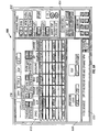
- An example of such an interface is shown in Figs. 6A and 6B .
- the display formats shown are exemplary, and any desired display format may be utilized for the purpose displaying dysfunctions and any other desired information.
- the downhole computed parameters of interest for which the severity level is to be displayed contain multiple levels using digital indicators 612 .
- FIG. 6A shows such parameters as being the drag, bit bounce, stick slip, torque shocks, BHA whirl, buckling and lateral vibration, each such parameter having eight levels marked 1-8. It should be noted that the present system is neither limited to nor requires using the above-noted parameters or any specific number of levels.
- the downhole computed parameters RPM, WOB, FLOW (drilling fluid flow rate) mud density and viscosity are shown displayed under the header "CONTROL PANEL" in block 602.
- the relative condition of the MWD, mud motor and the drill bit on a scale of 0-100%, 100% being the condition when such element is new, is displayed under the header "CONDITION” in block 604.
- Certain surface measured parameters, such as the WOB, torque on bit (TOB), drill bit depth and the drilling rate or the rate of penetration are displayed in block 606.
- Additional parameters of interest such as the surface drilling fluid pressure, pressure loss due to friction are shown displayed in block 608.
- a recommended corrective action developed by the neural network is displayed in block 610.
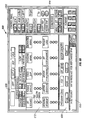
- FIG. 6B shows an alternative display format for use in the present system.
- the difference between this display and the display shown in FIG. 6A is that downhole computed parameter of interest that relates to the dysfunction contains three colors, green to indicate that the parameter is within a desired range, yellow to indicate that the dysfunction is present but is not severe, much like a warning signal, and red to indicate that the dysfunction is severe and should be corrected.
- any other suitable display format may be devised for use in the present invention.
- Figs. 6A-B show an operating screen 600 designed in the form of a front panel of an electronic device with relatively few controls and digital indicators. Interaction with the device is achieved using, for example, a mouse, a keyboard or a touch-sensitive screen. These devices are well known and thus not shown separately.
- Sliding bars are used for setting the values of different parameters at the control panel 602 and for providing information about their valid ranges.
- the sliding bars also allow the user to visually estimate the relative position of a selected value within the permissible range of a parameter.
- the digital indicators 612 relating to the dynamic dysfunctions also serve as indicators of severity levels. They change their colors (using "green-yellow-red" pattern) as the lever of severity changes.
- the user has to specify the current state of the plant by setting the values of the control parameters (controls) and the observed plant output (response). Once the system state is specified, the simulator can make an estimate of the plant output for any new control settings entered by the user.
- 3-D plots may be used as an output for any of the outputs from the plant as a function of any two control parameters.
- the plots representing dynamic dysfunctions show the value of the dysfunction colored according to severity. Color may be used in an ROP plot to represent the combined severity of all dynamic dysfunctions at each point.
- the user may also decide whether to enter new control settings manually or to engage an automated optimization module (see 504 in Fig. 5 ).
- This module simply plays different "what if” scenarios showing the development of the plant over one minute intervals each comprising three time steps. The time interval may be adjusted as any particular application might require.
- the optimization module 504 automatically selects new controls to maximize ROP while keeping the dynamic dysfunctions in acceptable limits or "green" zones.
- Time domain charts showing the evolution of the selected parameters over time may be used to help the user understand how an observed dynamic problem developed.
- the present methods allow for correction and plant stabilization in approximately 15 to 20 time steps, that is 5-6 minutes with each time step equal to 20 seconds. Reducing the dynamic dysfunctions in this manner can increase the ROP significantly.
- the NN simulator might "recommend” (1) increasing RPM while decreasing WOB and (2) bringing the values of the control parameters to new levels different from the original state.
- the method and apparatus of the present invention uses the power of Neural Networks (NN) to model dynamic behavior of a non-linear, multi-input/output drilling system.
- NN Neural Networks
- Such a model along with a controller, provides the driller with a quantified recommendation on the appropriate correction action(s) to provide improved efficiency in the drilling operations.
- the NN model is developed using drilling dynamics data from a field test.
- This field test involves various drilling scenarios in different lithologic units.
- the training and fine-tuning of the basic model utilizes both surface and downhole dynamics data recorded in real-time while drilling. Measurement of the dynamic state of the BHA is achieved using data from downhole vibration sensors. This information, which represents the effects of modifying surface control parameters, is recorded in the memory of the downhole tool. Representative portions of this test data set, along with the corresponding set of input-output control parameters, are used in developing and training the model.
- the present invention provides simulation and prediction of the dynamic behavior of a complex multi-parameter drilling system.
- the present invention provides an alternative to traditional analytic or direct numerical modeling and its utilization is extended beyond drilling, dynamics to the field of drilling control and optimization.
Landscapes
- Life Sciences & Earth Sciences (AREA)
- Engineering & Computer Science (AREA)
- Geology (AREA)
- Mining & Mineral Resources (AREA)
- Physics & Mathematics (AREA)
- Environmental & Geological Engineering (AREA)
- Fluid Mechanics (AREA)
- General Life Sciences & Earth Sciences (AREA)
- Geochemistry & Mineralogy (AREA)
- Earth Drilling (AREA)
- Feedback Control In General (AREA)
Applications Claiming Priority (2)
| Application Number | Priority Date | Filing Date | Title |
|---|---|---|---|
| US23658100P | 2000-09-29 | 2000-09-29 | |
| US236581P | 2000-09-29 |
Publications (2)
| Publication Number | Publication Date |
|---|---|
| EP1193366A2 true EP1193366A2 (fr) | 2002-04-03 |
| EP1193366A3 EP1193366A3 (fr) | 2002-10-09 |
Family
ID=22890093
Family Applications (1)
| Application Number | Title | Priority Date | Filing Date |
|---|---|---|---|
| EP01308364A Withdrawn EP1193366A3 (fr) | 2000-09-29 | 2001-10-01 | Procédé et dispositif de prévision des paramètres de forage utilisant un réseau neuronal |
Country Status (5)
| Country | Link |
|---|---|
| US (1) | US6732052B2 (fr) |
| EP (1) | EP1193366A3 (fr) |
| CA (1) | CA2357921C (fr) |
| GB (1) | GB2371625B (fr) |
| NO (1) | NO325151B1 (fr) |
Cited By (20)
| Publication number | Priority date | Publication date | Assignee | Title |
|---|---|---|---|---|
| CN100440090C (zh) * | 2007-02-07 | 2008-12-03 | 浙江大学 | 一种传感器测量网络的设计方法 |
| WO2009135157A3 (fr) * | 2008-05-02 | 2010-02-18 | Baker Hughes Incorporated | Système de commande de forage adaptatif |
| US7931096B2 (en) | 2005-08-30 | 2011-04-26 | Sandvik Mining And Construction Oy | Adaptive user interface for rock drilling rig |
| CN102168547A (zh) * | 2011-03-15 | 2011-08-31 | 中国石油大学(华东) | 一种基于小波神经网络的深水防喷器组故障诊断系统 |
| US8286726B2 (en) | 2005-08-30 | 2012-10-16 | Sandvik Mining And Construction Oy | User interface for rock drilling rig |
| WO2012109663A3 (fr) * | 2011-02-11 | 2013-03-14 | Schlumberger Canada Limited | Système et appareil pour la modélisation du comportement d'un ensemble de forage |
| EP2816194A1 (fr) * | 2013-06-19 | 2014-12-24 | Siemens Aktiengesellschaft | Procédé destiné à l'exécution d'un processus de forage profond |
| WO2015057099A1 (fr) * | 2013-10-18 | 2015-04-23 | Baker Hughes Incorporated | Prédiction d'aptitude au forage basée sur émissions électromagnétiques durant forage |
| NO337219B1 (no) * | 2002-05-21 | 2016-02-15 | Tde Thonhauser Data Eng Gmbh | Automatisert fremgangsmåte og system for å bestemme tilstanden til brønnoperasjoner |
| EP2954160A4 (fr) * | 2013-02-05 | 2016-02-17 | Services Petroliers Schlumberger | Système et méthode de gestion de processus de forage |
| WO2016069318A1 (fr) * | 2014-10-27 | 2016-05-06 | Board Of Regents, The University Of Texas System | Diagnostic de vibrations de forage adaptatif |
| EP3055501A4 (fr) * | 2013-10-10 | 2017-07-19 | Baker Hughes Incorporated | Gestion de durée de vie d'outils et de composants de fond de trou |
| US9995129B2 (en) | 2013-10-21 | 2018-06-12 | Halliburton Energy Services, Inc. | Drilling automation using stochastic optimal control |
| WO2019014362A3 (fr) * | 2017-07-11 | 2019-02-21 | Hrl Laboratories, Llc | Système et procédé d'estimation de forage de fond de trou à l'aide de graphiques temporels pour opération de forage autonome |
| US10385675B2 (en) | 2013-09-17 | 2019-08-20 | Halliburton Energy Services, Inc. | Estimation and calibration of downhole buckling conditions |
| WO2020046366A1 (fr) * | 2018-08-31 | 2020-03-05 | Landmark Graphics Corporation | Prédiction de type de réparation de trépan à l'aide de l'apprentissage machine |
| US10781683B2 (en) | 2015-03-06 | 2020-09-22 | Halliburton Energy Services, Inc. | Optimizing sensor selection and operation for well monitoring and control |
| NO345487B1 (en) * | 2015-05-12 | 2021-03-01 | Halliburton Energy Services Inc | Enhancing oilfield operations with cognitive computing |
| WO2023027757A1 (fr) * | 2021-08-26 | 2023-03-02 | Halliburton Energy Services, Inc. | Optimisation d'opérations de puits de forage pour un impact de durabilité |
| WO2023067391A1 (fr) * | 2021-10-22 | 2023-04-27 | Exebenus AS | Système et procédé de prédiction et d'optimisation de paramètres de forage |
Families Citing this family (174)
| Publication number | Priority date | Publication date | Assignee | Title |
|---|---|---|---|---|
| US6612382B2 (en) * | 1996-03-25 | 2003-09-02 | Halliburton Energy Services, Inc. | Iterative drilling simulation process for enhanced economic decision making |
| US7032689B2 (en) | 1996-03-25 | 2006-04-25 | Halliburton Energy Services, Inc. | Method and system for predicting performance of a drilling system of a given formation |
| US5794720A (en) * | 1996-03-25 | 1998-08-18 | Dresser Industries, Inc. | Method of assaying downhole occurrences and conditions |
| US6826486B1 (en) * | 2000-02-11 | 2004-11-30 | Schlumberger Technology Corporation | Methods and apparatus for predicting pore and fracture pressures of a subsurface formation |
| US8401831B2 (en) | 2000-03-13 | 2013-03-19 | Smith International, Inc. | Methods for designing secondary cutting structures for a bottom hole assembly |
| US7251590B2 (en) * | 2000-03-13 | 2007-07-31 | Smith International, Inc. | Dynamic vibrational control |
| US9482055B2 (en) | 2000-10-11 | 2016-11-01 | Smith International, Inc. | Methods for modeling, designing, and optimizing the performance of drilling tool assemblies |
| US7284623B2 (en) * | 2001-08-01 | 2007-10-23 | Smith International, Inc. | Method of drilling a bore hole |
| US6820702B2 (en) | 2002-08-27 | 2004-11-23 | Noble Drilling Services Inc. | Automated method and system for recognizing well control events |
| US8463441B2 (en) | 2002-12-09 | 2013-06-11 | Hudson Technologies, Inc. | Method and apparatus for optimizing refrigeration systems |
| US6662110B1 (en) * | 2003-01-14 | 2003-12-09 | Schlumberger Technology Corporation | Drilling rig closed loop controls |
| WO2004065749A2 (fr) * | 2003-01-17 | 2004-08-05 | Halliburton Energy Services, Inc. | Systeme dynamique integre de forage, et son mode de fonctionnement |
| FR2850129B1 (fr) * | 2003-01-22 | 2007-01-12 | Installation de commande pour des outils de fond de puits automatises. | |
| WO2004090285A1 (fr) * | 2003-03-31 | 2004-10-21 | Baker Hughes Incorporated | Optimisation de forage en temps reel basee sur des mesures dynamiques mwd |
| DE10324045B3 (de) * | 2003-05-27 | 2004-10-14 | Siemens Ag | Verfahren sowie Computerprogramm mit Programmcode-Mitteln und Computerprogramm-Produkt zur Ermittlung eines zukünftigen Systemverhaltens eines dynamischen Systems |
| US7139218B2 (en) * | 2003-08-13 | 2006-11-21 | Intelliserv, Inc. | Distributed downhole drilling network |
| US7054750B2 (en) * | 2004-03-04 | 2006-05-30 | Halliburton Energy Services, Inc. | Method and system to model, measure, recalibrate, and optimize control of the drilling of a borehole |
| GB2413403B (en) * | 2004-04-19 | 2008-01-09 | Halliburton Energy Serv Inc | Field synthesis system and method for optimizing drilling operations |
| US7337660B2 (en) * | 2004-05-12 | 2008-03-04 | Halliburton Energy Services, Inc. | Method and system for reservoir characterization in connection with drilling operations |
| US20060020390A1 (en) * | 2004-07-22 | 2006-01-26 | Miller Robert G | Method and system for determining change in geologic formations being drilled |
| US7680559B2 (en) * | 2005-02-08 | 2010-03-16 | Lam Research Corporation | Wafer movement control macros |
| US8344905B2 (en) | 2005-03-31 | 2013-01-01 | Intelliserv, Llc | Method and conduit for transmitting signals |
| US8827006B2 (en) * | 2005-05-12 | 2014-09-09 | Schlumberger Technology Corporation | Apparatus and method for measuring while drilling |
| JP2009503306A (ja) * | 2005-08-04 | 2009-01-29 | シュルンベルジェ ホールディングス リミテッド | 坑井遠隔計測システム用インターフェイス及びインターフェイス方法 |
| US9109439B2 (en) * | 2005-09-16 | 2015-08-18 | Intelliserv, Llc | Wellbore telemetry system and method |
| AU2006327196B2 (en) * | 2005-11-18 | 2011-05-12 | Exxonmobil Upstream Research Company | Method of drilling and producing hydrocarbons from subsurface formations |
| US7444861B2 (en) * | 2005-11-22 | 2008-11-04 | Halliburton Energy Services, Inc. | Real time management system for slickline/wireline |
| MX2007001832A (es) * | 2006-02-16 | 2008-11-18 | Intelliserv Inc | Descubrimiento de nodos en red de testigo lógica segmentada físicamente. |
| US20070278009A1 (en) * | 2006-06-06 | 2007-12-06 | Maximo Hernandez | Method and Apparatus for Sensing Downhole Characteristics |
| US7540337B2 (en) * | 2006-07-03 | 2009-06-02 | Mcloughlin Stephen John | Adaptive apparatus, system and method for communicating with a downhole device |
| US7857047B2 (en) * | 2006-11-02 | 2010-12-28 | Exxonmobil Upstream Research Company | Method of drilling and producing hydrocarbons from subsurface formations |
| US8672055B2 (en) * | 2006-12-07 | 2014-03-18 | Canrig Drilling Technology Ltd. | Automated directional drilling apparatus and methods |
| US7921937B2 (en) * | 2007-01-08 | 2011-04-12 | Baker Hughes Incorporated | Drilling components and systems to dynamically control drilling dysfunctions and methods of drilling a well with same |
| EP2108166B1 (fr) | 2007-02-02 | 2013-06-19 | ExxonMobil Upstream Research Company | Modélisation et conception d'un système de forage de puits qui amortit les vibrations |
| US8285531B2 (en) * | 2007-04-19 | 2012-10-09 | Smith International, Inc. | Neural net for use in drilling simulation |
| US20080314641A1 (en) * | 2007-06-20 | 2008-12-25 | Mcclard Kevin | Directional Drilling System and Software Method |
| US7957946B2 (en) * | 2007-06-29 | 2011-06-07 | Schlumberger Technology Corporation | Method of automatically controlling the trajectory of a drilled well |
| EP2198113B1 (fr) * | 2007-09-04 | 2017-08-16 | Stephen John Mcloughlin | Ensemble de fond de trou |
| US9109410B2 (en) * | 2007-09-04 | 2015-08-18 | George Swietlik | Method system and apparatus for reducing shock and drilling harmonic variation |
| US8121971B2 (en) * | 2007-10-30 | 2012-02-21 | Bp Corporation North America Inc. | Intelligent drilling advisor |
| WO2009058635A2 (fr) * | 2007-10-30 | 2009-05-07 | Bp Corporation North America Inc. | Système d'aide à la décision de forage intelligent |
| US8417495B2 (en) * | 2007-11-07 | 2013-04-09 | Baker Hughes Incorporated | Method of training neural network models and using same for drilling wellbores |
| GB2454701B (en) * | 2007-11-15 | 2012-02-29 | Schlumberger Holdings | Methods of drilling with a downhole drilling machine |
| WO2009075667A2 (fr) * | 2007-11-30 | 2009-06-18 | Halliburton Energy Services | Procédé et système pour prédire des performances d'un système de forage ayant de multiples structures de coupe |
| US8457897B2 (en) * | 2007-12-07 | 2013-06-04 | Exxonmobil Upstream Research Company | Methods and systems to estimate wellbore events |
| US8751164B2 (en) * | 2007-12-21 | 2014-06-10 | Schlumberger Technology Corporation | Production by actual loss allocation |
| EP2090742A1 (fr) | 2008-02-14 | 2009-08-19 | ExxonMobil Upstream Research Company | Procédés et systèmes pour évaluer les évènements d'un puits de forage |
| AU2009222010B2 (en) * | 2008-03-03 | 2015-06-25 | Intelliserv International Holding, Ltd | Monitoring downhole conditions with drill string distributed measurement system |
| EA018946B1 (ru) * | 2008-06-17 | 2013-11-29 | Эксонмобил Апстрим Рисерч Компани | Способы и системы для ослабления колебаний при бурении |
| US8413744B2 (en) * | 2008-07-31 | 2013-04-09 | Baker Hughes Incorporated | System and method for controlling the integrity of a drilling system |
| US20100042327A1 (en) * | 2008-08-13 | 2010-02-18 | Baker Hughes Incorporated | Bottom hole assembly configuration management |
| AU2009300240B2 (en) * | 2008-10-03 | 2013-02-21 | Halliburton Energy Services, Inc. | Method and system for predicting performance of a drilling system |
| WO2010059295A1 (fr) | 2008-11-21 | 2010-05-27 | Exxonmobil Upstream Research Company | Procédés et systèmes de modélisation, conception et conduite d'opérations de forage qui prennent en compte les vibrations |
| GB2466812B (en) | 2009-01-08 | 2011-10-19 | Schlumberger Holdings | Drillstring dynamics |
| US7823656B1 (en) | 2009-01-23 | 2010-11-02 | Nch Corporation | Method for monitoring drilling mud properties |
| NO338750B1 (no) | 2009-03-02 | 2016-10-17 | Drilltronics Rig Systems As | Fremgangsmåte og system for automatisert styring av boreprosess |
| WO2010101548A1 (fr) * | 2009-03-05 | 2010-09-10 | Halliburton Energy Services, Inc. | Analyse et commande du mouvement d'un train de tiges |
| EP3524944B1 (fr) | 2009-05-27 | 2022-07-20 | Halliburton Energy Services Inc. | Procédé d'analyse frequentielle en temps reel des modes de vibration dans un train de tiges de forage |
| CA2767370A1 (fr) * | 2009-08-07 | 2011-02-10 | Exxonmobil Upstream Research Company | Systemes et procedes d?assistance au forage utilisant des fonctions objectives |
| WO2011017626A1 (fr) | 2009-08-07 | 2011-02-10 | Exxonmobil Upstream Research Company | Procédés pour estimer une amplitude de vibration de forage de fond de trou à partir d'une mesure de surface |
| CA2767689C (fr) | 2009-08-07 | 2018-01-02 | Exxonmobil Upstream Research Company | Systeme et procedes d'assistance au forage bases sur au moins deux parametres de forage maitrisables |
| MY158575A (en) * | 2009-08-07 | 2016-10-14 | Exxonmobil Upstream Res Co | Methods to estimate downhole drilling vibration indices from surface measurement |
| US8676721B2 (en) * | 2009-09-18 | 2014-03-18 | Apo Offshore, Inc. | Method, system and apparatus for intelligent management of oil and gas platform surface equipment |
| US8453764B2 (en) * | 2010-02-01 | 2013-06-04 | Aps Technology, Inc. | System and method for monitoring and controlling underground drilling |
| US8473435B2 (en) * | 2010-03-09 | 2013-06-25 | Schlumberger Technology Corporation | Use of general bayesian networks in oilfield operations |
| US8799198B2 (en) * | 2010-03-26 | 2014-08-05 | Smith International, Inc. | Borehole drilling optimization with multiple cutting structures |
| CA2813729A1 (fr) * | 2010-11-17 | 2012-05-24 | Halliburton Energy Services, Inc. | Appareil et procede pour forer un puits |
| US9521418B2 (en) | 2011-07-22 | 2016-12-13 | Qualcomm Incorporated | Slice header three-dimensional video extension for slice header prediction |
| US11496760B2 (en) | 2011-07-22 | 2022-11-08 | Qualcomm Incorporated | Slice header prediction for depth maps in three-dimensional video codecs |
| US8688382B2 (en) * | 2011-07-25 | 2014-04-01 | Baker Hughes Incorporated | Detection of downhole vibrations using surface data from drilling rigs |
| US9288505B2 (en) * | 2011-08-11 | 2016-03-15 | Qualcomm Incorporated | Three-dimensional video with asymmetric spatial resolution |
| US9285794B2 (en) | 2011-09-07 | 2016-03-15 | Exxonmobil Upstream Research Company | Drilling advisory systems and methods with decision trees for learning and application modes |
| US9243489B2 (en) | 2011-11-11 | 2016-01-26 | Intelliserv, Llc | System and method for steering a relief well |
| US9485503B2 (en) | 2011-11-18 | 2016-11-01 | Qualcomm Incorporated | Inside view motion prediction among texture and depth view components |
| US9593567B2 (en) | 2011-12-01 | 2017-03-14 | National Oilwell Varco, L.P. | Automated drilling system |
| US9157309B1 (en) | 2011-12-22 | 2015-10-13 | Hunt Advanced Drilling Technologies, LLC | System and method for remotely controlled surface steerable drilling |
| US11085283B2 (en) | 2011-12-22 | 2021-08-10 | Motive Drilling Technologies, Inc. | System and method for surface steerable drilling using tactical tracking |
| US9404356B2 (en) | 2011-12-22 | 2016-08-02 | Motive Drilling Technologies, Inc. | System and method for remotely controlled surface steerable drilling |
| US8210283B1 (en) | 2011-12-22 | 2012-07-03 | Hunt Energy Enterprises, L.L.C. | System and method for surface steerable drilling |
| US9297205B2 (en) | 2011-12-22 | 2016-03-29 | Hunt Advanced Drilling Technologies, LLC | System and method for controlling a drilling path based on drift estimates |
| US8596385B2 (en) | 2011-12-22 | 2013-12-03 | Hunt Advanced Drilling Technologies, L.L.C. | System and method for determining incremental progression between survey points while drilling |
| US9512706B2 (en) | 2012-03-02 | 2016-12-06 | Schlumberger Technology Corporation | Agent registration in dynamic phase machine automation system |
| US9706185B2 (en) | 2012-04-16 | 2017-07-11 | Canrig Drilling Technology Ltd. | Device control employing three-dimensional imaging |
| US9057258B2 (en) | 2012-05-09 | 2015-06-16 | Hunt Advanced Drilling Technologies, LLC | System and method for using controlled vibrations for borehole communications |
| US8517093B1 (en) | 2012-05-09 | 2013-08-27 | Hunt Advanced Drilling Technologies, L.L.C. | System and method for drilling hammer communication, formation evaluation and drilling optimization |
| US9982532B2 (en) | 2012-05-09 | 2018-05-29 | Hunt Energy Enterprises, L.L.C. | System and method for controlling linear movement using a tapered MR valve |
| US9117169B2 (en) * | 2012-05-24 | 2015-08-25 | Halliburton Energy Services, Inc. | Methods and apparatuses for modeling shale characteristics in wellbore servicing fluids using an artificial neural network |
| US9157313B2 (en) | 2012-06-01 | 2015-10-13 | Intelliserv, Llc | Systems and methods for detecting drillstring loads |
| US9494033B2 (en) | 2012-06-22 | 2016-11-15 | Intelliserv, Llc | Apparatus and method for kick detection using acoustic sensors |
| US9482084B2 (en) | 2012-09-06 | 2016-11-01 | Exxonmobil Upstream Research Company | Drilling advisory systems and methods to filter data |
| US9309747B2 (en) * | 2012-09-14 | 2016-04-12 | Baker Hughes Incorporated | System and method for generating profile-based alerts/alarms |
| CA3064241C (fr) * | 2012-10-31 | 2022-12-13 | Resource Energy Solutions Inc. | Procedes et systemes pour operations de forage ameliorees utilisant des donnees de forage historiques et en temps reel |
| US9022140B2 (en) | 2012-10-31 | 2015-05-05 | Resource Energy Solutions Inc. | Methods and systems for improved drilling operations using real-time and historical drilling data |
| CA2911270A1 (fr) * | 2013-05-08 | 2014-11-13 | Technological Resources Pty Ltd | Procede et systeme pour commander une operation de forage |
| US8818729B1 (en) | 2013-06-24 | 2014-08-26 | Hunt Advanced Drilling Technologies, LLC | System and method for formation detection and evaluation |
| US10920576B2 (en) | 2013-06-24 | 2021-02-16 | Motive Drilling Technologies, Inc. | System and method for determining BHA position during lateral drilling |
| US8996396B2 (en) | 2013-06-26 | 2015-03-31 | Hunt Advanced Drilling Technologies, LLC | System and method for defining a drilling path based on cost |
| USD843381S1 (en) | 2013-07-15 | 2019-03-19 | Aps Technology, Inc. | Display screen or portion thereof with a graphical user interface for analyzing and presenting drilling data |
| US9435187B2 (en) | 2013-09-20 | 2016-09-06 | Baker Hughes Incorporated | Method to predict, illustrate, and select drilling parameters to avoid severe lateral vibrations |
| US10472944B2 (en) | 2013-09-25 | 2019-11-12 | Aps Technology, Inc. | Drilling system and associated system and method for monitoring, controlling, and predicting vibration in an underground drilling operation |
| US9645575B2 (en) | 2013-11-27 | 2017-05-09 | Adept Ai Systems Inc. | Method and apparatus for artificially intelligent model-based control of dynamic processes using probabilistic agents |
| MX362604B (es) | 2013-12-06 | 2019-01-28 | Halliburton Energy Services Inc | Control de un arreglo de fondo de pozo en un pozo. |
| MX381393B (es) * | 2013-12-06 | 2025-03-12 | Halliburton Energy Services Inc | Control de operaciones de pozos. |
| CN105874159B (zh) | 2013-12-06 | 2019-12-31 | 哈利伯顿能源服务公司 | 控制井下钻井设备的计算机实现方法和井筒系统 |
| US9784099B2 (en) * | 2013-12-18 | 2017-10-10 | Baker Hughes Incorporated | Probabilistic determination of health prognostics for selection and management of tools in a downhole environment |
| US10400572B2 (en) | 2013-12-30 | 2019-09-03 | Halliburton Energy Services, Inc. | Apparatus and methods using drillability exponents |
| US20150218888A1 (en) * | 2014-02-04 | 2015-08-06 | Chevron U.S.A. Inc. | Well construction geosteering apparatus, system, and process |
| US9828845B2 (en) | 2014-06-02 | 2017-11-28 | Baker Hughes, A Ge Company, Llc | Automated drilling optimization |
| US9428961B2 (en) | 2014-06-25 | 2016-08-30 | Motive Drilling Technologies, Inc. | Surface steerable drilling system for use with rotary steerable system |
| US11106185B2 (en) | 2014-06-25 | 2021-08-31 | Motive Drilling Technologies, Inc. | System and method for surface steerable drilling to provide formation mechanical analysis |
| US10221671B1 (en) * | 2014-07-25 | 2019-03-05 | U.S. Department Of Energy | MSE based drilling optimization using neural network simulaton |
| WO2016043723A1 (fr) * | 2014-09-16 | 2016-03-24 | Halliburton Energy Services, Inc. | Classification et analyse de bruit de forage |
| US9890633B2 (en) | 2014-10-20 | 2018-02-13 | Hunt Energy Enterprises, Llc | System and method for dual telemetry acoustic noise reduction |
| US11713671B2 (en) | 2014-10-28 | 2023-08-01 | Halliburton Energy Services, Inc. | Downhole state-machine-based monitoring of vibration |
| US9784880B2 (en) | 2014-11-20 | 2017-10-10 | Schlumberger Technology Corporation | Compensated deep propagation measurements with differential rotation |
| US11125070B2 (en) * | 2015-05-08 | 2021-09-21 | Schlumberger Technology Corporation | Real time drilling monitoring |
| CN107709702B (zh) * | 2015-05-13 | 2021-09-03 | 科诺科菲利浦公司 | 用于功率损失故障表征的方法、系统和装置 |
| WO2016183205A1 (fr) * | 2015-05-13 | 2016-11-17 | Conocophillips Company | Caractérisation de dysfonctionnement à perte de puissance |
| EP3294990B1 (fr) * | 2015-05-13 | 2025-06-25 | ConocoPhillips Company | Grand moteur d'analyse de données de forage |
| US10410298B1 (en) | 2015-06-08 | 2019-09-10 | DataInfoCom USA, Inc. | Systems and methods for analyzing resource production |
| US10352099B2 (en) | 2015-09-02 | 2019-07-16 | Exxonmobil Upstream Research Company | Methods for drilling a wellbore within a subsurface region and drilling assemblies that include and/or utilize the methods |
| GB2559282B (en) * | 2015-10-30 | 2021-07-21 | Halliburton Energy Services Inc | Enhancing drilling operations with cognitive computing |
| US20170122092A1 (en) | 2015-11-04 | 2017-05-04 | Schlumberger Technology Corporation | Characterizing responses in a drilling system |
| US10495778B2 (en) | 2015-11-19 | 2019-12-03 | Halliburton Energy Services, Inc. | System and methods for cross-tool optical fluid model validation and real-time application |
| US11933158B2 (en) | 2016-09-02 | 2024-03-19 | Motive Drilling Technologies, Inc. | System and method for mag ranging drilling control |
| US11422999B2 (en) | 2017-07-17 | 2022-08-23 | Schlumberger Technology Corporation | System and method for using data with operation context |
| US10968730B2 (en) | 2017-07-25 | 2021-04-06 | Exxonmobil Upstream Research Company | Method of optimizing drilling ramp-up |
| EP3665355B1 (fr) | 2017-08-10 | 2026-01-21 | Motive Drilling Technologies, Inc. | Appareil et procédés de forage par glissière automatique |
| US10830033B2 (en) | 2017-08-10 | 2020-11-10 | Motive Drilling Technologies, Inc. | Apparatus and methods for uninterrupted drilling |
| CA3069128C (fr) | 2017-08-14 | 2022-01-25 | Exxonmobil Upstream Research Company | Procedes de forage d'un puits de forage dans une region souterraine et systemes de commande de forage qui mettent en oeuvre les procedes |
| US11319793B2 (en) * | 2017-08-21 | 2022-05-03 | Landmark Graphics Corporation | Neural network models for real-time optimization of drilling parameters during drilling operations |
| US10866962B2 (en) | 2017-09-28 | 2020-12-15 | DatalnfoCom USA, Inc. | Database management system for merging data into a database |
| US11131181B2 (en) | 2017-10-09 | 2021-09-28 | Exxonmobil Upstream Research Company | Controller with automatic tuning and method |
| US12055028B2 (en) | 2018-01-19 | 2024-08-06 | Motive Drilling Technologies, Inc. | System and method for well drilling control based on borehole cleaning |
| US11613983B2 (en) | 2018-01-19 | 2023-03-28 | Motive Drilling Technologies, Inc. | System and method for analysis and control of drilling mud and additives |
| US11346215B2 (en) * | 2018-01-23 | 2022-05-31 | Baker Hughes Holdings Llc | Methods of evaluating drilling performance, methods of improving drilling performance, and related systems for drilling using such methods |
| GB2582096B (en) | 2018-01-29 | 2022-04-27 | Landmark Graphics Corp | Controlling range constraints for real-time drilling |
| WO2019183412A1 (fr) | 2018-03-21 | 2019-09-26 | Massachusetts Institute Of Technology | Systèmes et procédés pour détecter une conversion sismique-électromagnétique |
| US10563500B2 (en) * | 2018-04-06 | 2020-02-18 | Baker Hughes, A Ge Company, Llc | Performing an action at a wellbore operation based on anonymized data |
| US10577924B2 (en) * | 2018-04-06 | 2020-03-03 | Baker Hughes, A Ge Company, Llc | Performing an action at a wellbore operation based on anonymized data |
| GB2585581B (en) * | 2018-05-09 | 2022-06-01 | Landmark Graphics Corp | Learning based Bayesian optimization for optimizing controllable drilling parameters |
| WO2019217653A1 (fr) | 2018-05-09 | 2019-11-14 | Massachusetts Institute Of Technology | Systèmes et procédés de déconvolution aveugle focalisée |
| CN108825202A (zh) * | 2018-07-23 | 2018-11-16 | 中国石油集团渤海钻探工程有限公司 | 一种底部钻具动力学参数信号处理电路及处理方法 |
| NO20201431A1 (en) * | 2018-08-02 | 2020-12-22 | Landmark Graphics Corp | Operating wellbore equipment using a distributed decision framework |
| GB2590238B (en) | 2018-08-30 | 2022-06-29 | Landmark Graphics Corp | Automated rate of penetration optimization for drilling |
| US11100595B2 (en) * | 2018-10-03 | 2021-08-24 | Schweitzer Engineering Laboratories, Inc. | Electric power system pricing with energy packets |
| CN111119835A (zh) * | 2018-11-01 | 2020-05-08 | 中国石油化工股份有限公司 | 一种随钻工况识别方法及系统 |
| US10890060B2 (en) | 2018-12-07 | 2021-01-12 | Schlumberger Technology Corporation | Zone management system and equipment interlocks |
| US10907466B2 (en) | 2018-12-07 | 2021-02-02 | Schlumberger Technology Corporation | Zone management system and equipment interlocks |
| US20200182038A1 (en) * | 2018-12-10 | 2020-06-11 | National Oilwell Varco, L.P. | High-speed analytics and virtualization engine |
| US10808517B2 (en) | 2018-12-17 | 2020-10-20 | Baker Hughes Holdings Llc | Earth-boring systems and methods for controlling earth-boring systems |
| WO2020159525A1 (fr) * | 2019-01-31 | 2020-08-06 | Landmark Graphics Corporation | Systèmes de pompe et procédés pour améliorer des prédictions de charge de pompe |
| US11466556B2 (en) | 2019-05-17 | 2022-10-11 | Helmerich & Payne, Inc. | Stall detection and recovery for mud motors |
| US11674384B2 (en) * | 2019-05-20 | 2023-06-13 | Schlumberger Technology Corporation | Controller optimization via reinforcement learning on asset avatar |
| EP3980817A1 (fr) | 2019-06-06 | 2022-04-13 | Massachusetts Institute Of Technology | Estimation séquentielle pendant le forage |
| US12008440B2 (en) | 2019-09-04 | 2024-06-11 | Halliburton Energy Services, Inc. | Dynamic drilling dysfunction codex |
| US10920703B1 (en) | 2019-10-14 | 2021-02-16 | Schweitzer Engineering Laboratories, Inc. | Systems, methods and apparatuses for wet stack residue mitigation |
| MX2022006898A (es) | 2019-12-05 | 2022-09-19 | Geoquest Systems Bv | Sistema y método para predecir el atascamiento-deslizamiento. |
| US11409592B2 (en) | 2020-02-13 | 2022-08-09 | Baker Hughes Oilfield Operations Llc | Methods of predicting electronic component failures in an earth-boring tool and related systems and apparatus |
| US11131184B1 (en) | 2020-04-29 | 2021-09-28 | Saudi Arabian Oil Company | Method and system for determining a drilling hazard condition using well logs |
| WO2021243021A1 (fr) * | 2020-05-27 | 2021-12-02 | Erdos Miller, Inc. | Procédé et appareil pour couper des objets dans un puits sous-marin et sceller le puits de production dudit puits |
| RU2735794C1 (ru) * | 2020-06-23 | 2020-11-09 | Федеральное государственное автономное образовательное учреждение высшего образования "Южно-Уральский государственный университет (национальный исследовательский университет)" ФГАОУ ВО "ЮУрГУ (НИУ)" | Способ прогнозирования прихватов бурильных труб |
| US11391144B2 (en) | 2020-06-26 | 2022-07-19 | Landmark Graphics Corporation | Autonomous wellbore drilling with satisficing drilling parameters |
| US11879321B2 (en) * | 2020-08-24 | 2024-01-23 | Helmerich & Payne Technologies, Llc | Methods and systems for drilling |
| US11702923B2 (en) * | 2020-08-24 | 2023-07-18 | Helmerich & Payne Technologies, Llc | Methods and systems for drilling |
| US11867008B2 (en) * | 2020-11-05 | 2024-01-09 | Saudi Arabian Oil Company | System and methods for the measurement of drilling mud flow in real-time |
| CN112502613B (zh) | 2020-11-27 | 2022-01-07 | 中国科学院地质与地球物理研究所 | 一种钻井方法及装置 |
| US12297732B2 (en) * | 2021-06-15 | 2025-05-13 | Schlumberger Technology Corporation | Drilling control |
| US11885212B2 (en) | 2021-07-16 | 2024-01-30 | Helmerich & Payne Technologies, Llc | Apparatus and methods for controlling drilling |
| US11965407B2 (en) | 2021-12-06 | 2024-04-23 | Saudi Arabian Oil Company | Methods and systems for wellbore path planning |
| US11867055B2 (en) | 2021-12-08 | 2024-01-09 | Saudi Arabian Oil Company | Method and system for construction of artificial intelligence model using on-cutter sensing data for predicting well bit performance |
| US12378878B2 (en) * | 2022-03-30 | 2025-08-05 | Saudi Arabian Oil Company | Method and system for managing drilling parameters based on downhole vibrations and artificial intelligence |
| US20250239055A1 (en) * | 2023-04-13 | 2025-07-24 | Aramco Innovations LLC | Systems and methods for preparing a lithologically balanced training set |
| US12503937B1 (en) * | 2024-08-23 | 2025-12-23 | ADS Services, LLC | Autonomous drilling system with integrated AI |
Citations (2)
| Publication number | Priority date | Publication date | Assignee | Title |
|---|---|---|---|---|
| US6206108B1 (en) | 1995-01-12 | 2001-03-27 | Baker Hughes Incorporated | Drilling system with integrated bottom hole assembly |
| US6233524B1 (en) | 1995-10-23 | 2001-05-15 | Baker Hughes Incorporated | Closed loop drilling system |
Family Cites Families (16)
| Publication number | Priority date | Publication date | Assignee | Title |
|---|---|---|---|---|
| US4739841A (en) | 1986-08-15 | 1988-04-26 | Anadrill Incorporated | Methods and apparatus for controlled directional drilling of boreholes |
| JPH06203005A (ja) | 1992-10-27 | 1994-07-22 | Eastman Kodak Co | 高速区分化ニューラルネットワーク及びその構築方法 |
| JP3213897B2 (ja) | 1993-06-07 | 2001-10-02 | 清水建設株式会社 | 掘削機の自動偏位修正方法及び装置並びに掘削機の掘削速度制御方法 |
| US5812068A (en) * | 1994-12-12 | 1998-09-22 | Baker Hughes Incorporated | Drilling system with downhole apparatus for determining parameters of interest and for adjusting drilling direction in response thereto |
| US6012015A (en) * | 1995-02-09 | 2000-01-04 | Baker Hughes Incorporated | Control model for production wells |
| GB9603982D0 (en) | 1996-02-26 | 1996-04-24 | Univ Aberdeen | Moling apparatus and a ground sensing system therefor |
| GB9614761D0 (en) * | 1996-07-13 | 1996-09-04 | Schlumberger Ltd | Downhole tool and method |
| US5947213A (en) | 1996-12-02 | 1999-09-07 | Intelligent Inspection Corporation | Downhole tools using artificial intelligence based control |
| US6002985A (en) * | 1997-05-06 | 1999-12-14 | Halliburton Energy Services, Inc. | Method of controlling development of an oil or gas reservoir |
| US6044325A (en) | 1998-03-17 | 2000-03-28 | Western Atlas International, Inc. | Conductivity anisotropy estimation method for inversion processing of measurements made by a transverse electromagnetic induction logging instrument |
| DE19941197C2 (de) | 1998-09-23 | 2003-12-04 | Fraunhofer Ges Forschung | Steuerung für ein Horizontalbohrgerät |
| US6276465B1 (en) | 1999-02-24 | 2001-08-21 | Baker Hughes Incorporated | Method and apparatus for determining potential for drill bit performance |
| US6490527B1 (en) | 1999-07-13 | 2002-12-03 | The United States Of America As Represented By The Department Of Health And Human Services | Method for characterization of rock strata in drilling operations |
| EP1126129A1 (fr) | 2000-02-18 | 2001-08-22 | Brownline B.V. | Système de guidage pour forage horizontal et dirigé |
| US6424919B1 (en) * | 2000-06-26 | 2002-07-23 | Smith International, Inc. | Method for determining preferred drill bit design parameters and drilling parameters using a trained artificial neural network, and methods for training the artificial neural network |
| US6722450B2 (en) | 2000-11-07 | 2004-04-20 | Halliburton Energy Svcs. Inc. | Adaptive filter prediction method and system for detecting drill bit failure and signaling surface operator |
-
2001
- 2001-09-28 US US09/965,958 patent/US6732052B2/en not_active Expired - Lifetime
- 2001-09-28 NO NO20014722A patent/NO325151B1/no not_active IP Right Cessation
- 2001-09-28 GB GB0123432A patent/GB2371625B/en not_active Expired - Lifetime
- 2001-09-28 CA CA002357921A patent/CA2357921C/fr not_active Expired - Lifetime
- 2001-10-01 EP EP01308364A patent/EP1193366A3/fr not_active Withdrawn
Patent Citations (2)
| Publication number | Priority date | Publication date | Assignee | Title |
|---|---|---|---|---|
| US6206108B1 (en) | 1995-01-12 | 2001-03-27 | Baker Hughes Incorporated | Drilling system with integrated bottom hole assembly |
| US6233524B1 (en) | 1995-10-23 | 2001-05-15 | Baker Hughes Incorporated | Closed loop drilling system |
Cited By (35)
| Publication number | Priority date | Publication date | Assignee | Title |
|---|---|---|---|---|
| NO337219B1 (no) * | 2002-05-21 | 2016-02-15 | Tde Thonhauser Data Eng Gmbh | Automatisert fremgangsmåte og system for å bestemme tilstanden til brønnoperasjoner |
| US7931096B2 (en) | 2005-08-30 | 2011-04-26 | Sandvik Mining And Construction Oy | Adaptive user interface for rock drilling rig |
| US8286726B2 (en) | 2005-08-30 | 2012-10-16 | Sandvik Mining And Construction Oy | User interface for rock drilling rig |
| CN100440090C (zh) * | 2007-02-07 | 2008-12-03 | 浙江大学 | 一种传感器测量网络的设计方法 |
| WO2009135157A3 (fr) * | 2008-05-02 | 2010-02-18 | Baker Hughes Incorporated | Système de commande de forage adaptatif |
| NO20101565A (no) * | 2008-05-02 | 2010-11-24 | Baker Hughes Holdings Llc | Adaptivt borestyringssystem |
| GB2472715A (en) * | 2008-05-02 | 2011-02-16 | Baker Hughes Inc | Adaptive drilling control system |
| GB2472715B (en) * | 2008-05-02 | 2012-12-26 | Baker Hughes Inc | Adaptive drilling control system |
| NO347231B1 (no) * | 2008-05-02 | 2023-07-17 | Baker Hughes Holdings Llc | Adaptivt borestyringssystem |
| WO2012109663A3 (fr) * | 2011-02-11 | 2013-03-14 | Schlumberger Canada Limited | Système et appareil pour la modélisation du comportement d'un ensemble de forage |
| US8775145B2 (en) | 2011-02-11 | 2014-07-08 | Schlumberger Technology Corporation | System and apparatus for modeling the behavior of a drilling assembly |
| CN102168547A (zh) * | 2011-03-15 | 2011-08-31 | 中国石油大学(华东) | 一种基于小波神经网络的深水防喷器组故障诊断系统 |
| US10400573B2 (en) | 2013-02-05 | 2019-09-03 | Schlumberger Technology Corporation | System and method for controlling drilling process |
| EP2954160A4 (fr) * | 2013-02-05 | 2016-02-17 | Services Petroliers Schlumberger | Système et méthode de gestion de processus de forage |
| EP2816194A1 (fr) * | 2013-06-19 | 2014-12-24 | Siemens Aktiengesellschaft | Procédé destiné à l'exécution d'un processus de forage profond |
| US10385675B2 (en) | 2013-09-17 | 2019-08-20 | Halliburton Energy Services, Inc. | Estimation and calibration of downhole buckling conditions |
| US10876926B2 (en) | 2013-10-10 | 2020-12-29 | Baker Hughes Holdings Llc | Life-time management of downhole tools and components |
| EP3055501A4 (fr) * | 2013-10-10 | 2017-07-19 | Baker Hughes Incorporated | Gestion de durée de vie d'outils et de composants de fond de trou |
| US9857271B2 (en) | 2013-10-10 | 2018-01-02 | Baker Hughes, A Ge Company, Llc | Life-time management of downhole tools and components |
| RU2657277C2 (ru) * | 2013-10-18 | 2018-06-09 | Бейкер Хьюз Инкорпорейтед | Прогнозирование буримости исходя из электромагнитного излучения, испускаемого в ходе буровых работ |
| CN106164708A (zh) * | 2013-10-18 | 2016-11-23 | 贝克休斯公司 | 基于钻探期间的电磁发射预测可钻性 |
| US10344533B2 (en) | 2013-10-18 | 2019-07-09 | Baker Hughes, A Ge Company, Llc | Predicting drillability based on electromagnetic emissions during drilling |
| CN106164708B (zh) * | 2013-10-18 | 2019-07-23 | 贝克休斯公司 | 基于钻探期间的电磁发射预测可钻性 |
| WO2015057099A1 (fr) * | 2013-10-18 | 2015-04-23 | Baker Hughes Incorporated | Prédiction d'aptitude au forage basée sur émissions électromagnétiques durant forage |
| US9995129B2 (en) | 2013-10-21 | 2018-06-12 | Halliburton Energy Services, Inc. | Drilling automation using stochastic optimal control |
| WO2016069318A1 (fr) * | 2014-10-27 | 2016-05-06 | Board Of Regents, The University Of Texas System | Diagnostic de vibrations de forage adaptatif |
| US10781683B2 (en) | 2015-03-06 | 2020-09-22 | Halliburton Energy Services, Inc. | Optimizing sensor selection and operation for well monitoring and control |
| NO345487B1 (en) * | 2015-05-12 | 2021-03-01 | Halliburton Energy Services Inc | Enhancing oilfield operations with cognitive computing |
| US11168558B2 (en) | 2015-05-12 | 2021-11-09 | Halliburton Energy Services, Inc. | Enhancing oilfield operations with cognitive computing |
| WO2019014362A3 (fr) * | 2017-07-11 | 2019-02-21 | Hrl Laboratories, Llc | Système et procédé d'estimation de forage de fond de trou à l'aide de graphiques temporels pour opération de forage autonome |
| US11676000B2 (en) | 2018-08-31 | 2023-06-13 | Halliburton Energy Services, Inc. | Drill bit repair type prediction using machine learning |
| WO2020046366A1 (fr) * | 2018-08-31 | 2020-03-05 | Landmark Graphics Corporation | Prédiction de type de réparation de trépan à l'aide de l'apprentissage machine |
| WO2023027757A1 (fr) * | 2021-08-26 | 2023-03-02 | Halliburton Energy Services, Inc. | Optimisation d'opérations de puits de forage pour un impact de durabilité |
| US11797165B2 (en) | 2021-08-26 | 2023-10-24 | Envana Software Solutions, Llc | Optimizing wellbore operations for sustainability impact |
| WO2023067391A1 (fr) * | 2021-10-22 | 2023-04-27 | Exebenus AS | Système et procédé de prédiction et d'optimisation de paramètres de forage |
Also Published As
| Publication number | Publication date |
|---|---|
| GB2371625A8 (en) | 2004-02-24 |
| GB2371625B (en) | 2003-09-10 |
| EP1193366A3 (fr) | 2002-10-09 |
| CA2357921A1 (fr) | 2002-03-29 |
| NO20014722D0 (no) | 2001-09-28 |
| NO20014722L (no) | 2002-04-02 |
| US6732052B2 (en) | 2004-05-04 |
| GB0123432D0 (en) | 2001-11-21 |
| GB2371625A (en) | 2002-07-31 |
| NO325151B1 (no) | 2008-02-11 |
| US20020120401A1 (en) | 2002-08-29 |
| CA2357921C (fr) | 2007-02-06 |
Similar Documents
| Publication | Publication Date | Title |
|---|---|---|
| CA2357921C (fr) | Methode et appareil utilisant les reseaux neuronaux pour la commande predictive en dynamique de forage | |
| US6233524B1 (en) | Closed loop drilling system | |
| US8417495B2 (en) | Method of training neural network models and using same for drilling wellbores | |
| US6206108B1 (en) | Drilling system with integrated bottom hole assembly | |
| US5842149A (en) | Closed loop drilling system | |
| US8818779B2 (en) | System and methods for real-time wellbore stability service | |
| US7142986B2 (en) | System for optimizing drilling in real time | |
| NO20190967A1 (en) | Tool-Specific Steering Optimization to Hit a Target | |
| WO1998017894A9 (fr) | Dispositif de forage a ensemble fond de puits integre | |
| WO1998017894A2 (fr) | Dispositif de forage a ensemble fond de puits integre | |
| NO348457B1 (en) | Statistical approach to incorporate uncertainties of parameters in simulation results and stability analysis for earth drilling | |
| Aldred et al. | Drilling automation | |
| CN109072672A (zh) | 定向钻井控制系统和方法 | |
| WO2016179766A1 (fr) | Surveillance de forage en temps réel | |
| EP4264012B1 (fr) | Réglages dynamiques de limites de paramètres de forage | |
| US20250277436A1 (en) | Drilling Optimization Method | |
| US20100038137A1 (en) | Apparatus and Method for Generating Sector Residence Time Images of Downhole Tools | |
| US11280190B2 (en) | Estimation of a downhole fluid property distribution | |
| CA2269498C (fr) | Dispositif de forage a ensemble fond de puits integre | |
| US20240418071A1 (en) | Rop optimization |
Legal Events
| Date | Code | Title | Description |
|---|---|---|---|
| PUAI | Public reference made under article 153(3) epc to a published international application that has entered the european phase |
Free format text: ORIGINAL CODE: 0009012 |
|
| AK | Designated contracting states |
Kind code of ref document: A2 Designated state(s): AT BE CH CY DE DK ES FI FR GB GR IE IT LI LU MC NL PT SE TR |
|
| AX | Request for extension of the european patent |
Free format text: AL;LT;LV;MK;RO;SI |
|
| PUAL | Search report despatched |
Free format text: ORIGINAL CODE: 0009013 |
|
| AK | Designated contracting states |
Kind code of ref document: A3 Designated state(s): AT BE CH CY DE DK ES FI FR GB GR IE IT LI LU MC NL PT SE TR |
|
| AX | Request for extension of the european patent |
Free format text: AL;LT;LV;MK;RO;SI |
|
| 17P | Request for examination filed |
Effective date: 20030404 |
|
| AKX | Designation fees paid |
Designated state(s): DE FR IT NL |
|
| RIN1 | Information on inventor provided before grant (corrected) |
Inventor name: KRUEGER, VOLKER Inventor name: DASHEVSKIY, DMITRIY Inventor name: MACDONALD, ROBERT P. Inventor name: DUBINSKY, VLADIMIR Inventor name: MACPHERSON, JOHN D. |
|
| RAP1 | Party data changed (applicant data changed or rights of an application transferred) |
Owner name: BACKER HUGUES INCORPORATED |
|
| RAP1 | Party data changed (applicant data changed or rights of an application transferred) |
Owner name: BAKER HUGHES INCORPORATED |
|
| 17Q | First examination report despatched |
Effective date: 20051026 |
|
| STAA | Information on the status of an ep patent application or granted ep patent |
Free format text: STATUS: THE APPLICATION IS DEEMED TO BE WITHDRAWN |
|
| 18D | Application deemed to be withdrawn |
Effective date: 20071026 |