EP1195533B1 - Boulon de serrage - Google Patents
Boulon de serrage Download PDFInfo
- Publication number
- EP1195533B1 EP1195533B1 EP99924022A EP99924022A EP1195533B1 EP 1195533 B1 EP1195533 B1 EP 1195533B1 EP 99924022 A EP99924022 A EP 99924022A EP 99924022 A EP99924022 A EP 99924022A EP 1195533 B1 EP1195533 B1 EP 1195533B1
- Authority
- EP
- European Patent Office
- Prior art keywords
- shaft
- fastening
- bolt
- nut
- hydraulic pressure
- Prior art date
- Legal status (The legal status is an assumption and is not a legal conclusion. Google has not performed a legal analysis and makes no representation as to the accuracy of the status listed.)
- Expired - Lifetime
Links
Images



Classifications
-
- B—PERFORMING OPERATIONS; TRANSPORTING
- B23—MACHINE TOOLS; METAL-WORKING NOT OTHERWISE PROVIDED FOR
- B23P—METAL-WORKING NOT OTHERWISE PROVIDED FOR; COMBINED OPERATIONS; UNIVERSAL MACHINE TOOLS
- B23P19/00—Machines for simply fitting together or separating metal parts or objects, or metal and non-metal parts, whether or not involving some deformation; Tools or devices therefor so far as not provided for in other classes
- B23P19/04—Machines for simply fitting together or separating metal parts or objects, or metal and non-metal parts, whether or not involving some deformation; Tools or devices therefor so far as not provided for in other classes for assembling or disassembling parts
- B23P19/06—Screw or nut setting or loosening machines
- B23P19/067—Bolt tensioners
-
- F—MECHANICAL ENGINEERING; LIGHTING; HEATING; WEAPONS; BLASTING
- F16—ENGINEERING ELEMENTS AND UNITS; GENERAL MEASURES FOR PRODUCING AND MAINTAINING EFFECTIVE FUNCTIONING OF MACHINES OR INSTALLATIONS; THERMAL INSULATION IN GENERAL
- F16B—DEVICES FOR FASTENING OR SECURING CONSTRUCTIONAL ELEMENTS OR MACHINE PARTS TOGETHER, e.g. NAILS, BOLTS, CIRCLIPS, CLAMPS, CLIPS OR WEDGES; JOINTS OR JOINTING
- F16B31/00—Screwed connections specially modified in view of tensile load; Break-bolts
- F16B31/04—Screwed connections specially modified in view of tensile load; Break-bolts for maintaining a tensile load
- F16B31/043—Prestressed connections tensioned by means of liquid, grease, rubber, explosive charge, or the like
-
- F—MECHANICAL ENGINEERING; LIGHTING; HEATING; WEAPONS; BLASTING
- F16—ENGINEERING ELEMENTS AND UNITS; GENERAL MEASURES FOR PRODUCING AND MAINTAINING EFFECTIVE FUNCTIONING OF MACHINES OR INSTALLATIONS; THERMAL INSULATION IN GENERAL
- F16B—DEVICES FOR FASTENING OR SECURING CONSTRUCTIONAL ELEMENTS OR MACHINE PARTS TOGETHER, e.g. NAILS, BOLTS, CIRCLIPS, CLAMPS, CLIPS OR WEDGES; JOINTS OR JOINTING
- F16B39/00—Locking of screws, bolts or nuts
- F16B39/02—Locking of screws, bolts or nuts in which the locking takes place after screwing down
- F16B39/10—Locking of screws, bolts or nuts in which the locking takes place after screwing down by a plate, spring, wire or ring immovable with regard to the bolt or object and mainly perpendicular to the axis of the bolt
-
- F—MECHANICAL ENGINEERING; LIGHTING; HEATING; WEAPONS; BLASTING
- F16—ENGINEERING ELEMENTS AND UNITS; GENERAL MEASURES FOR PRODUCING AND MAINTAINING EFFECTIVE FUNCTIONING OF MACHINES OR INSTALLATIONS; THERMAL INSULATION IN GENERAL
- F16B—DEVICES FOR FASTENING OR SECURING CONSTRUCTIONAL ELEMENTS OR MACHINE PARTS TOGETHER, e.g. NAILS, BOLTS, CIRCLIPS, CLAMPS, CLIPS OR WEDGES; JOINTS OR JOINTING
- F16B2200/00—Constructional details of connections not covered for in other groups of this subclass
- F16B2200/89—Use of a hydraulic action
Definitions
- the present invention relates to a fastening bolt used in combination with a nut for fastening objects such as flanges.
- the bolt has a head portion formed as a larger outer diameter portion at one end of the shaft, and an outer thread formed on the circumference of the shaft for engaging with inner thread of the nut.
- the objects are fastened between the head portion and the nut, and the fastening force between them is adjusted by tightening the nut, and the fastening length is adjusted by using washer or spacer.
- a bottom portion of a reduction furnace separable, because interior of the bottom portion is covered with a firebrick lining which needs periodical repair.
- This separable construction of the furnace makes the plant more cost effective than to install two furnaces so that one furnace can be repaired while the other furnace is in operation.
- the smelting furnace in the commercial plant has a large volume, and a large number of fastening bolts are needed for connecting the bottom portion to the furnace body with flanges. Air tightness is required at the flange connecting portion because the smelting reduction furnace is operated under high internal pressure of several kgf/cm 2 G, and quick replacement of the bottom portion is also required to prevent drop of plant operating efficiency.
- conventional bolts and nuts are used for fastening flanges, a large number of bolts and nuts should be fastened uniformly to keep air tightness, and unfastened for releasing flanges.
- FIG 11 shows a prior art of a bolt disclosed in Japanese Utility Model Laid-Open No. Sho 63-157407, which is fastened utilizing hydraulic pressure.
- a guide base 1a is secured on a rest bar 3 by fastening a clamp 2, and by unfastening the clamp 2 the rest bar 3 is slidable along the rest bar 3 in the direction perpendicular to the surface of the drawing.
- a fastening shaft 4 for creating fastening force is inserted into a piston 5 combined with a cylinder 8.
- a lock nut 7 attached on the end of the shaft 4 is pushed apart by the piston 5 in the axial direction of the shaft 4.
- a reaction force of the piston 5 against the lock nut 7 is applied on the clamp 2 by the cylinder 8.
- FIG. 11 shows the condition when no hydraulic pressure is applied.
- the end surface of the cylinder 8 is fastened by a fastening nut 9 attached on the circumference of the piston 5.
- the piston 5 is moved in the direction away from the head portion of the fastening shaft 4, and a gap G is formed between end surfaces of the cylinder 8 and the fastening nut 9.
- the lock nut 7 is pushed by the piston 5 away from the head portion 4 to extend the shaft 4 in axial direction.
- the fastening nut 9 When the gap G is formed, the fastening nut 9 is rotated to come into contact again with the end surface of the cylinder 8. Relative movement between the piston 5 and the cylinder 8 is then restricted by the fastening nut 9, and the position of the lock nut 7 shown in the lower half of the Figure 11 can be maintained after the hydraulic pressure is released.
- a convex nut 12 and a concave nut 13 are disposed between the clamp 2 and the cylinder 8, and a spacer 14 is disposed between the end surfaces of the piston 5 and the lock nut 7.
- a large number of bolts can be securely fastened utilizing hydraulic pressure.
- Another prior arts of such bolts utilizing hydraulic pressure for fastening are disclosed in Japanese Laid-Open Patent Publication No. Hei 2-262971 and Japanese Laid-Open Patent Publication No. Hei 5-79302.
- the former includes means for creating fastening force in a turn buckle by extending the bolt with hydraulic pressure, and means for locking the fastened condition after the hydraulic pressure is released.
- the latter includes tension nuts connected at both ends of the bolt, and one tension nut is pulled up by a hydraulic cylinder to create prescribed fastening force, and the pulled up condition is retained by fastening a nut.
- US-A-4884934 discloses a fastening bolt according to the preamble of claims 1 and 3 hereinafter.
- fastening bolt with a simple structure with easy fastening and unfastening operation, and with no adjustment of the fastening force being required in respective fastening operation.
- the present invention provides a fastening bolt for fastening an object between a head portion formed on one end of a shaft and a nut attached on a threaded portion formed around the shaft, wherein said fastening bolt includes a hydraulic pressure application means for applying hydraulic pressure to extend the shaft between said head portion and said threaded portion while said object is fastened between said head portion and said nut, and for releasing a fastened condition of said object, characterised in that said head portion is formed in a hammer shape by a removably attached cotter which extends in the direction perpendicular to the axis of said shaft.
- the present invention also provides a fastening bolt for fastening an object between a head portion formed on one end of a shaft and a nut attached on a threaded portion formed around the shaft, wherein said fastening bolt includes a hydraulic pressure application means for applying a hydraulic pressure to extend the shaft between said head portion and said threaded portion while said object is fastened between said head portion and said nut, and for releasing a fastened condition of said object, wherein said hydraulic pressure application means includes a combination of a cylinder and a piston and said cylinder and said piston are moved apart in the axial direction of said shaft when the hydraulic pressure is applied, wherein either one of said cylinder or said piston is connected to said shaft, and the other one of said cylinder or said piston pushes said nut to move apart from said head portion when the hydraulic pressure is applied, characterised in that said head portion has a hammer shape which extends in the direction perpendicular to the axis of the shaft and said hammer shape is formed by a removably attached cotter
- the shaft of the fastening bolt can be extended between the head portion and the nut where the object is fastened by the application of hydraulic pressure, and when the shaft is extended, the nut can be easily rotated for releasing the fastened condition.
- By tightening the nut when the shaft is extended large fastening force is obtained after the hydraulic pressure is released, and the fastening force can also be adjusted easily by the adjustment of the hydraulic pressure.
- the object is fastened between the head portion and the nut attached on the threaded portion, and the shaft is extended between the head portion and the nut by the application of hydraulic pressure by the hydraulic pressure application means, and fastened condition of the object is released to become unfastened condition. In the unfastened condition, the nut can be easily rotated and can also be removed from the shaft.
- This fastening condition corresponds to the condition when the nut is tightened with relatively strong fastening force.
- the force needed to tighten the nut while the shaft is extended by the hydraulic pressure can be set to such a degree that the nut is manually rotatable, and the final of fastening force can be adjusted by the hydraulic pressure.
- the head portion is formed in a hammer shape by a removably attached cotter which extends in the direction perpendicular to the axis of the shaft. Therefore, the fastening bolt can easily be withdrawn from the object by removing the cotter from the head portion. More particularly, when the cotter extending in the direction perpendicular to the axis of the shaft is attached, the head portion is prevented from passing through the bolt hole with a slightly larger inner diameter than the outside diameter of the shaft of the fastening bolt, enabling the object to be fastened. When the cotter is removed from the head portion of the fastening bolt, the shaft of the fastening bolt can easily be withdrawn through the bolt hole formed in the object, and can be easily withdrawn from the bolt hole to release the object.
- a cavity is formed within the shaft to be extended, and the hydraulic pressurizing means is adapted to apply and release hydraulic pressure in the cavity.
- the shaft can be extended by a simple construction because the shaft is extended by the application of hydraulic pressure in the cavity. More particularly, when the cavity formed within the shaft is pressurized by the hydraulic pressurizing means, the shaft is extended by the internal pressure in the cavity, and the shaft returns to its original length when the hydraulic pressure in the cavity is released.
- the means for applying pressure includes a combination of a cylinder and piston, wherein the cylinder and the piston are moved apart in the axial direction of the shaft by the application of the hydraulic pressure, and wherein either one of the cylinder or the piston is connected to the shaft, and the other one of the cylinder or the piston pushes the nut away from the head portion by application of the hydraulic pressure.
- the combination of cylinder and piston is provided for the extension of the shaft, which is profitable for a small diameter shaft in which it is difficult to form a cavity. More particularly, the combination of cylinder and piston is provided in the hydraulic pressurizing means. When the hydraulic pressure is applied, the cylinder and piston are moved apart each other in the axial direction of the shaft of the fastening bolt, and either one of the cylinder or piston is connected to the shaft and the other one of the cylinder or the piston presses the nut away from the head portion, thus, the shaft can be extended by the application of hydraulic pressure to separate apart between the shaft and the nut.
- a collar may extend in the axial direction of the shaft between the fastened object and the nut.
- the shaft can be extended sufficiently by a relatively low pressure because the length of the shaft is increased by the collar. More particularly, the collar extending in the axial direction of the shaft is provided between the fastened object and the nut, increasing the length of the extendable portion of the shaft, within which the hydraulic pressurizing means is easily mounted.
- the object is fastened via spherical washers.
- uniform fastening force is obtained by the spherical washers. More particularly, the object is fastened via spherical washers having centering function to apply uniform fastening force around the axis of the shaft.
- Figure 1 shows a basic structure of a fastening bolt 20 as the first embodiment of the present invention.
- Figure 1 (a) shows the fastened condition
- Figure 1 (b) shows the unfastened condition.
- the fastening bolt 20 is used for fastening objects such as flanges 21, 22.
- a shaft 23 to be inserted through flanges 21, 22 has a bolt head 24 on one end.
- a threaded portion 25 is formed on the circumference toward the other end of the shaft 23, and a cavity 26 is formed within the shaft 23.
- the cavity 26 has an inner thread 27 toward the other end in the axial direction for inserting a plug 28.
- the plug 28 seals the cavity 26.
- the plug 28 has a hydraulic pressure port 29 for supplying pressure hydraulic fluid into the cavity 26.
- hydraulic pressure application means includes the cavity 26, the plug 28 and the fluid port 29.
- Figure 1 (a) shows the fastening condition with no hydraulic pressure applied in the cavity 26, fastening flanges 21, 22 between the bolt head 24 and a nut 30 connected to the threaded portion 25.
- Spherical washers 31, 32 having a centering function are provided between flange 22 and the nut 30 to apply uniform fastening force upon the flange 22.
- Figure 1 (b) shows the extended condition of the shaft 23 with the hydraulic pressure applied in the cavity 26 through the port 29.
- the shaft 23 is extended, and gaps 33, 34 which correspond to the amount of extension, are created between the nut 30 and the bolt head 24.
- the fastening force by the nut 30 disappears, and the nut 30 can be easily be removed by hand from the threaded portion 25.
- the fastening force can be adjusted by the hydraulic pressure in the cavity 26.
- the fastening force can be determined by the sum of the width of the gap 33 between the spherical washers 31, 32 and the nut 30, and the gap 34 between the flange 21 and the bolt head 24. In this case, the fastening force is increased when the sum of the gaps is smaller.
- FIG. 2 shows a fastening bolt 40 as a second embodiment of the present invention.
- the hydraulic pressure application means includes a cavity 46, a plug 48 and a fluid port 49.
- the cavity 46 formed in the shaft 43 in this embodiment is smaller in volume compared to the cavity 26 in the embodiment shown in Figure 1.
- a large quantity of hydraulic fluid always exists in the fastening bolt 20 because of a large volume of the cavity 26.
- the present embodiment has an advantage that the amount of hydraulic fluid can be reduced because of a small volume of the cavity 46.
- a large volume of hydraulic fluid increases the influence of thermal expansion of hydraulic fluid.
- the volume of hydraulic fluid is smaller, the pressure in the cavity 46 drops drastically with the small extension of the shaft 43. Therefore, the influence of the thermal expansion of the hydraulic fluid in the cavity 46 upon the amount of extension can be minimized.
- Figure 3 shows a fastening bolt 50 as a third embodiment of the present invention.
- the length of the shaft 53 as well as the length of the cavity 56 is increased in the axial direction of the shaft.
- the amount of extension of the shaft 53 is increased with respect to the pressure of hydraulic fluid introduced through the port 59 in the plug 58 attached with inner thread 57 at the end of the cavity 56.
- a cylindrical collar 55 is inserted between the spherical washer 32 and the nut 30 for adjusting the fastening length.
- FIG. 4 shows a fastening bolt 60 as a fourth embodiment of the present invention.
- the bolt 61 in this embodiment has no cavity formed in the shaft 63.
- the shaft 63 has a bolt head 24 formed on one end and a threaded portion 65 formed on the circumference toward the other end.
- a protruding portion 66 is provided on the shaft 63 on the position toward the other side from the portion passing through the flanges 21, 22.
- the other end side of the protruding portion 66 of the shaft 63 is inserted in a combination of a cylinder 67 and piston 68.
- the cylinder 67 has a fluid inlet port 69 which communicates with the abutted portion of the cylinder 67 and piston 68.
- the cylinder 67, piston 68 and port 69 form the hydraulic pressure application means in this embodiment.
- a nut 70 is threadably connected to the threaded portion 65.
- Spherical washers 71, 72 and a collar 75 are disposed between the nut 70 and the flange 22.
- the piston 68 is slidable in the cylinder 67 in the axial direction of the bolt 61.
- Figure 4 (a) shows the fastened condition with no hydraulic fluid supplied from the fluid port 69
- Figure 4 (b) shows the unfastened condition with the hydraulic fluid supplied from the fluid port 69 to separate abutted portion of the cylinder 67 and the piston 68 to form a pressurizing space 77.
- the formation of the pressurizing space 77 increases the length of the shaft 63 between the protruding portion 66 and the nut 70, and also increases the length between the bolt head 24 and nut 70, creating gaps between the bolt head 24 and the flange 21 or between the collar 75 and the nut 70.
- the flanges 21, 22 are fastened together between the bolt head 24 and the nut 70 via the spherical washers 71, 72 and the cylindrical collar 75.
- the protruding portion 66 of the bolt 61 can be formed by such as welding a nut. Combination of cylinder 67 and piston 68 is located between the protruding portion 66 and the nut 70.
- shaft 63 of the bolt 61 is extended by the movement of the piston 68 which moves apart from the cylinder 67 to press the nut 70.
- the flanges 21, 22 can be fastened by the contraction of the bolt 61. Sliding portion between the cylinder 67 and the piston 68 is sealed by an O-ring 76 to prevent leakage of hydraulic fluid. After the position of the nut 70 has been set, rotation of the nut 70 is locked. Hydraulic pressure is applied through a flexible hose or the like. The length of the shaft 63 is increased, when the amount of extension of the bolt 61 is not sufficient.
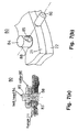
- Figure 5 shows the fastening condition and function of the bolt head 24 shown in the first embodiment.
- Figures 5 and 6 arrangements are not embodiments of the invention and are given for information purposes only.
- Figure 5 (a) shows a side view
- Figure 5 (b) shows a plan view.
- the bolt head 24 has a hammer shape extending in the direction 24a perpendicular to the axis 23a of the shaft 23.
- the flange 21 has a rectangular bolt hole 78 formed to correspond the outer shape of the bolt head 24.
- Figure 6 shows the condition in which the bolt head 24 can pass through the bolt hole 78 by aligning the axis 24a of the bolt head 24 with the axis 78a of the bolt hole 78 formed in the flange 21.
- Figure 6 (a) is a plan view showing that the outer shape the bolt head 24 is accommodated within the rectangular sectional shape of the bolt hole 78, allowing the bolt head 24 shown in the side views in Figure 6 (b) to be withdrawn through the bolt hole 78, to the condition shown in Figure 6 (c).
- the bolt head 24 can be easily withdrawn through the bolt holes 78 formed in flanges 21 and 22, by rotating the bolt head 24 from the direction shown in Figure 5 to the direction shown in Figure 6 during the unfastened condition when the bolt is extended as shown in Figure 1 (b) or Figure 4 (b).
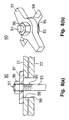
- FIG 7 partially shows a fastening bolt 80 as a fifth embodiment of the present invention.
- the bolt head 84 of the fastening bolt 80 has a cotter hole 85 in which a cotter 86 is removably attached.
- a bolt hole 88 is formed in the fastened object such as flange 21, 22 through which the shaft 83 of the fastening bolt 80 can pass.
- the fastening bolt 80 cannot pass through the bolt hole 88.
- the bolt head 84 can pass through the bolt hole 88. Therefore, the fastening bolt 80 can be removed from the fastened object by removing the cotter 86.
- the removal of the cotter 86 in this embodiment can easily be performed in the same manner during the unfastened condition when the shaft is extended such as shown in Figure 1 (b).
- the side surface of the cotter 86 is pressed strongly against the surface of the flange 21, and the removal of the cotter 86 is difficult.
- FIG 8 partially shows a fastening bolt 90 given for information purposes only.
- a bolt 91 in this embodiment is fastened via a hammer forming elongated spacer 97 by a nut 96 connected to the threaded portion 95 formed toward the end of a shaft 93. Consequently, a bolt with an ordinary head shape can be used as the bolt 91.
- the hammer forming elongated spacer 97 has an elongated shape extending in the direction parallel to the contact surfaces of the flanges 21, 22, and bolt holes 98, 99 formed in the flanges 21, 22 correspond to the shape of the elongated spacer 97.
- the bolt 91 including the elongated spacer 97 and the nut 96 can be removed from the flanges 21, 22 by aligning the direction of bolt holes 98, 99 with the direction of the elongated spacer 97 when the nut 96 is sized to pass through the bolt holes 98, 99.
- the nut 96 is sufficiently loosened at first, the bolt 91 is passed through the bolt holes 98, 99 together with the nut 96 and the elongated spacer 97, and the spacer 97 is rotated in the direction shown in Figure 8. Then, the hydraulic pressure is applied to extend the bolt 91, and the nut 96 is tightened manually while the bolt 91 is extended, until the nut 96, the elongated spacer 97 and the flange 21 come into contact with each other. Then by releasing the hydraulic pressure to zero, the flanges 21, 22 are fastened together by the contraction of the bolt 91.
- applied hydraulic pressure is constant, fastening force of all bolts can be made substantially constant, irrespective of slight roughness that may exist on the surface of the flanges 21, 22.
- Such structure can also be applied on the side of head portion. That is, the hammer shaped head is not formed integrally with the shaft but is formed separately as a spacer, and another nut is disposed on the other side of the fastened object to limit the axial position of the hammer shaped head.
- the axial position of the hammer shaped head can be adjusted easily by another nut connected to the shaft on the outer side of the head portion while the fastening bolt is extended.
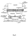
- FIG 9 shows the configuration of a flange fastening equipment using fastening bolts 20 in the embodiment shown in Figure 1.
- a furnace 100 is, for example, a smelting reduction furnace for making molten iron under the smelting reduction process, and the furnace is divided into a furnace bottom 101 and a furnace body 102. Inner surface of the furnace bottom 101 is covered with a firebrick liner which needs repairing due to wearing caused during the operation. For the repairing of the liner, the furnace bottom 101 is separated from the furnace body 102.
- the furnace body 102 and furnace bottom 101 are provided with flanges 21, 22 respectively, and by connecting the flanges 21, 22 with fastening bolts 20 the furnace 100 becomes operable.
- the furnace 100 is supported by a furnace support unit 103, and is also tiltable on the axis of this furnace support unit 103.
- a furnace bottom carrier 104 running on rails 105 moves into the location below the furnace 100 for the replacement of the furnace bottom 101.
- a lifter 106 is mounted on the furnace bottom carrier 104.
- the furnace bottom 101 is held on the lifter 106 which is raised to connect the furnace bottom 101 to the furnace body 102, or lowered to remove the furnace bottom 101 from the furnace body 102.
- the furnace bottom 101 has a bolt support 107 below the flange 22 for supporting the lower end of respective fastening bolt 20. Because lower end of fastening bolt 20 is held by the bolt support 107, a gap is created between the upper surface of the flange 21 and the lower surface of the bolt head of each fastening bolt 20 when it is extended by the hydraulic pressure. In the extended condition, the bolt head of respective fastening bolts 20 is freely rotatable so that the direction of the bolt heads can be changed easily from the fastened condition shown in Figure 5 to the unfastened condition shown in Figure 6.
- Hydraulic liquid pipe 108 is connected to each fastening bolt 20 for supplying and discharging hydraulic liquid.
- a hydraulic unit 110 is connected to the pipe 108 via a pipe connector 109.
- a hydraulic fluid pump and a hydraulic fluid tank are stored in the hydraulic unit 110.
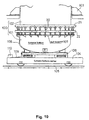
- Figure 10 shows the released condition in which all fastening bolts 20 are withdrawn from the flange 21, and the furnace bottom 101 together with all fastening bolts 20, flange 22 and bolt support 107 are lowered by lowering the lifter 106, after the bolt heads of the fastening bolts 20 are aligned with the orientation of the bolt holes formed in the flange 21.
- the furnace bottom carrier 104 running along the rails 105 carries the furnace bottom 110 away from the location just below the furnace body 102.
- new furnace bottom 101 with firebrick inner lining already repaired at another place is moved into the location just below the furnace body 102 as shown in Figure 10.
- the furnace can continue its operation using another furnace bottom 101 while one furnace bottom 101 is being repaired.
- the new furnace bottom 101 is raised by the lifter 106 from the position shown in Figure 10 and is connected to the furnace body 102.
- the bolt heads of the fastening bolts 20 pass through the bolt holes having specific orientation formed in the upper flange 21.
- the hydraulic fluid is supplied from the hydraulic unit 110 to extend each fastening bolts 20.
- the heads of the fastening bolts 20 are turned 90 degrees as shown in Figure 5 in the direction that the head can not pass through the bolt holes formed in the upper flange 21.
- the hydraulic pressure to the fastening bolts 20 is released and the hydraulic fluid is discharged by actuating the hydraulic unit 110, to bring each fastening bolts 20 into fastened condition.
- the flanges 21 and 22 can be fastened uniformly because the fastening force of the fastening bolts 20 can be adjusted by the gaps formed while the fastening bolts 20 are extended, and all fastening bolts 20 can be fastened simultaneously after the hydraulic pressure is released. It is also possible to divide the fastening bolts 20 into groups so that fastening and unfastening can be performed in groups.
- the fastening surfaces of the flanges 21 and 22 shown in Figures 9 and 10 are disposed horizontally.
- the fastening bolt of the described embodiments is also applicable to horizontal connection of vertical fastening surfaces, or tilted connection of slanted fastening surfaces.
- the fastening bolts are not limited to the fastening of flanges but also applicable for fastening a variety of objects by a combination of bolts and nuts.
- the fastening bolts shown in Figures 9 and 10 are positioned on the lower flange 22 side when flanges are opened. However, the fastening bolts can also be positioned on the upper flange 21 side by reversing position of each bolt.
- the fastening bolts embodying the invention as described above can fasten and unfasten with a simple structure, and the adjustment of the fastening force is not needed for respective fasting operation.
Landscapes
- Engineering & Computer Science (AREA)
- General Engineering & Computer Science (AREA)
- Mechanical Engineering (AREA)
- Clamps And Clips (AREA)
- Connection Of Plates (AREA)
- Hand Tools For Fitting Together And Separating, Or Other Hand Tools (AREA)
- Dowels (AREA)
- Pressure Vessels And Lids Thereof (AREA)
- Gripping Jigs, Holding Jigs, And Positioning Jigs (AREA)
Claims (5)
- Boulon de fixation (20 ; 40 ; 50 ; 60 ; 80) pour fixer un objet (21, 22) entre une partie formant tête (24) définie sur l'une des extrémités d'une tige (23 ; 43 ; 53 ; 63 ; 83) et un écrou (30 ; 70) fixé sur une partie filetée (25 ; 65) formée autour de la tige, ledit boulon de fixation comprenant des moyens d'application de pression hydraulique (26, 28, 29 ; 46, 48, 49 ; 56, 58, 59 ; 67, 68, 69) destinés à appliquer une pression hydraulique pour allonger la tige entre ladite partie formant tête et ladite partie filetée pendant que ledit objet est fixé entre ladite partie formant tête et ledit écrou, et à dégager ledit objet de son état de fixation, caractérisé en ce que ladite partie formant tête se présente sous la forme d'un maillet grâce à une goupille (86) fixée de façon amovible qui s'étend dans la direction perpendiculaire à l'axe de ladite tige.
- Boulon de fixation selon la revendication 1, dans lequel une cavité (26 ; 46 ; 56) est formée à l'intérieur de ladite tige destinée à être allongée, lesdits moyens d'application de pression hydraulique étant adaptés pour appliquer et détendre la pression hydraulique dans ladite cavité.
- Boulon de fixation (60 ; 80) pour fixer un objet (21, 22) entre une partie formant tête (24) définie sur l'une des extrémités d'une tige (63 ; 83) et un écrou (70) fixé sur une partie filetée (65) formée autour de la tige, ledit boulon de fixation comprenant des moyens d'application de pression hydraulique (67, 68, 69) destinés à appliquer une pression hydraulique pour allonger la tige entre ladite partie formant tête et ladite partie filetée pendant que ledit objet est fixé entre ladite partie formant tête et ledit écrou, et à dégager ledit objet de son état de fixation, et lesdits moyens d'application de pression hydraulique comprenant en combinaison un cylindre (67) et un piston (68) qui sont éloignés l'un de l'autre dans la direction axiale de ladite tige lorsque la pression hydraulique est appliquée et dont l'un est relié à ladite tige tandis que l'autre oblige ledit écrou à s'éloigner de ladite partie formant tête lorsque la pression hydraulique est appliquée, caractérisé en ce que ladite partie formant tête se présente sous la forme d'un maillet qui s'étend dans la direction perpendiculaire à l'axe de la tige, ladite forme de maillet étant réalisée grâce à une goupille (86) fixée de façon amovible.
- Boulon de fixation selon l'une des revendications 1 à 3, dans lequel un manchon (55 ; 75) s'étendant dans la direction axiale de ladite tige (53 ; 63) est disposé entre ledit objet (21, 22) et ledit écrou (30 ; 70).
- Boulon de fixation selon l'une des revendications 1 à 4, dans lequel ledit objet (21, 22) est fixé par l'intermédiaire de rondelles sphériques (31, 32 ; 71, 72).
Applications Claiming Priority (1)
| Application Number | Priority Date | Filing Date | Title |
|---|---|---|---|
| PCT/JP1999/003168 WO2000077409A1 (fr) | 1997-12-17 | 1999-06-14 | Boulon de serrage |
Publications (3)
| Publication Number | Publication Date |
|---|---|
| EP1195533A1 EP1195533A1 (fr) | 2002-04-10 |
| EP1195533A4 EP1195533A4 (fr) | 2003-03-19 |
| EP1195533B1 true EP1195533B1 (fr) | 2004-10-06 |
Family
ID=14235954
Family Applications (1)
| Application Number | Title | Priority Date | Filing Date |
|---|---|---|---|
| EP99924022A Expired - Lifetime EP1195533B1 (fr) | 1999-06-14 | 1999-06-14 | Boulon de serrage |
Country Status (6)
| Country | Link |
|---|---|
| EP (1) | EP1195533B1 (fr) |
| AT (1) | ATE278882T1 (fr) |
| AU (1) | AU750927B2 (fr) |
| CA (1) | CA2374859C (fr) |
| DE (1) | DE69920978T2 (fr) |
| WO (1) | WO2000077409A1 (fr) |
Families Citing this family (1)
| Publication number | Priority date | Publication date | Assignee | Title |
|---|---|---|---|---|
| CN114857156B (zh) * | 2022-04-24 | 2024-08-27 | 中国石油化工股份有限公司 | 一种双定位螺纹装配结构及方法 |
Family Cites Families (12)
| Publication number | Priority date | Publication date | Assignee | Title |
|---|---|---|---|---|
| US2934968A (en) * | 1957-12-23 | 1960-05-03 | Moeller & Neumann Gmbh | Hydraulic bolt stressing system |
| DE2161093C2 (de) * | 1971-12-09 | 1981-12-17 | Schmidt, Kranz & Co Gmbh, Zweigniederlassung Maschinenbau, 3421 Zorge | Hydraulisch beaufschlagbare Vorspannvorrichtung für Stehbolzen |
| GB1382191A (en) * | 1972-03-08 | 1975-01-29 | Doncaster Sons Ltd Daniel | Hydraulic jacking devices |
| SE375832B (fr) * | 1973-12-14 | 1975-04-28 | Motala Verkstad Ab | |
| SU524932A2 (ru) * | 1975-06-30 | 1976-08-15 | Болт | |
| SU1082980A1 (ru) * | 1980-03-26 | 1984-03-30 | Ленинградский Филиал Всесоюзного Института По Проектированию Организации Энергетического Строительства "Оргэнергострой" | Способ соединени фланцев вала гидроагрегата |
| GB2153946B (en) * | 1984-01-28 | 1987-10-14 | Hydra Tight Ltd | Hydraulic bolt tensioner |
| JPH0755414B2 (ja) * | 1986-10-01 | 1995-06-14 | 株式会社東芝 | 接合ボルトおよびその締付力の調整方法 |
| JPH03127813U (fr) * | 1990-04-09 | 1991-12-24 | ||
| US5842263A (en) * | 1996-01-11 | 1998-12-01 | Westinghouse Electric Corporation | Method and manufacture of an axial tensioned bolt |
| FR2750720A1 (fr) * | 1996-07-02 | 1998-01-09 | Pignatelli Francois | Collier a clavettes destine en particulier a l'assemblage de tubes d'echafaudages |
| JPH10318240A (ja) * | 1997-05-21 | 1998-12-02 | Komatsu Ltd | 位置決め機構 |
-
1999
- 1999-06-14 AT AT99924022T patent/ATE278882T1/de not_active IP Right Cessation
- 1999-06-14 DE DE69920978T patent/DE69920978T2/de not_active Expired - Fee Related
- 1999-06-14 AU AU40619/99A patent/AU750927B2/en not_active Ceased
- 1999-06-14 EP EP99924022A patent/EP1195533B1/fr not_active Expired - Lifetime
- 1999-06-14 CA CA002374859A patent/CA2374859C/fr not_active Expired - Fee Related
- 1999-06-14 WO PCT/JP1999/003168 patent/WO2000077409A1/fr not_active Ceased
Also Published As
| Publication number | Publication date |
|---|---|
| EP1195533A1 (fr) | 2002-04-10 |
| ATE278882T1 (de) | 2004-10-15 |
| AU750927B2 (en) | 2002-08-01 |
| CA2374859A1 (fr) | 2000-12-21 |
| AU4061999A (en) | 2001-01-02 |
| CA2374859C (fr) | 2006-07-25 |
| DE69920978D1 (de) | 2004-11-11 |
| DE69920978T2 (de) | 2006-02-23 |
| WO2000077409A1 (fr) | 2000-12-21 |
| EP1195533A4 (fr) | 2003-03-19 |
Similar Documents
| Publication | Publication Date | Title |
|---|---|---|
| US6216766B1 (en) | Fluid-tight coupling device for a feeder pipe | |
| CA2393693C (fr) | Dispositif de fermeture de couvercle | |
| CA1151702A (fr) | Raccord de tuyauterie a collier de serrage chaine | |
| AU2019359770B2 (en) | Hydraulic tensioning and release tool for expansion fasteners | |
| US6506007B1 (en) | Fastening bolt | |
| CN110307236A (zh) | 一种防松螺栓装置 | |
| BRPI0708023A2 (pt) | porca hidráulica de corpo único | |
| EP1195533B1 (fr) | Boulon de serrage | |
| CN101317033A (zh) | 夹紧卡箍或管卡箍 | |
| EP3404221B1 (fr) | Appareil de service de turbomachine et procédé associé | |
| CA2955592C (fr) | Assemblage d’essieu amovible | |
| ZA200109485B (en) | Tightening bolt. | |
| WO2003053611A1 (fr) | Moule de coulee en continu, cadre a petit cote de ce moule, et procede de remplacement de ce cadre a petit cote | |
| CA2955578C (fr) | Assemblage d'essieu | |
| CN114483728B (zh) | 一种t-bolt带锁槽卡箍及其制造方法及其应用 | |
| JPH11182759A (ja) | フランジ締結装置 | |
| US20110109024A1 (en) | Apparatus for insertion and extraction of fuel injection lances into and out of the tuyere stock of a furnace blast | |
| CN219603621U (zh) | 一种转炉喷补机工作臂 | |
| KR200257801Y1 (ko) | 슈트 내부 고착광 제거장치 | |
| KR200202475Y1 (ko) | 노즐 전용 예열토치 | |
| KR0118370Y1 (ko) | 체결력 유지장치를 가지는 타이어 가류용 금형 | |
| JPH04185971A (ja) | 流体圧を利用したフランジ部の組立分解装置 | |
| JPH0579302A (ja) | タービン車室の締結方法及び締結補助装置 | |
| CA2530553A1 (fr) | Methode de reparation des dommages causes par des collisions | |
| EP0507128A3 (en) | Compensator locking device |
Legal Events
| Date | Code | Title | Description |
|---|---|---|---|
| PUAI | Public reference made under article 153(3) epc to a published international application that has entered the european phase |
Free format text: ORIGINAL CODE: 0009012 |
|
| 17P | Request for examination filed |
Effective date: 20020108 |
|
| AK | Designated contracting states |
Kind code of ref document: A1 Designated state(s): AT DE NL |
|
| A4 | Supplementary search report drawn up and despatched |
Effective date: 20030130 |
|
| 17Q | First examination report despatched |
Effective date: 20031111 |
|
| GRAP | Despatch of communication of intention to grant a patent |
Free format text: ORIGINAL CODE: EPIDOSNIGR1 |
|
| GRAS | Grant fee paid |
Free format text: ORIGINAL CODE: EPIDOSNIGR3 |
|
| GRAA | (expected) grant |
Free format text: ORIGINAL CODE: 0009210 |
|
| AK | Designated contracting states |
Kind code of ref document: B1 Designated state(s): AT DE NL |
|
| REF | Corresponds to: |
Ref document number: 69920978 Country of ref document: DE Date of ref document: 20041111 Kind code of ref document: P |
|
| PLBE | No opposition filed within time limit |
Free format text: ORIGINAL CODE: 0009261 |
|
| STAA | Information on the status of an ep patent application or granted ep patent |
Free format text: STATUS: NO OPPOSITION FILED WITHIN TIME LIMIT |
|
| 26N | No opposition filed |
Effective date: 20050707 |
|
| PGFP | Annual fee paid to national office [announced via postgrant information from national office to epo] |
Ref country code: NL Payment date: 20060604 Year of fee payment: 8 |
|
| PGFP | Annual fee paid to national office [announced via postgrant information from national office to epo] |
Ref country code: DE Payment date: 20060608 Year of fee payment: 8 |
|
| PGFP | Annual fee paid to national office [announced via postgrant information from national office to epo] |
Ref country code: AT Payment date: 20060613 Year of fee payment: 8 |
|
| PG25 | Lapsed in a contracting state [announced via postgrant information from national office to epo] |
Ref country code: AT Free format text: LAPSE BECAUSE OF NON-PAYMENT OF DUE FEES Effective date: 20070614 |
|
| NLV4 | Nl: lapsed or anulled due to non-payment of the annual fee |
Effective date: 20080101 |
|
| PG25 | Lapsed in a contracting state [announced via postgrant information from national office to epo] |
Ref country code: NL Free format text: LAPSE BECAUSE OF NON-PAYMENT OF DUE FEES Effective date: 20080101 Ref country code: DE Free format text: LAPSE BECAUSE OF NON-PAYMENT OF DUE FEES Effective date: 20080101 |