EP1196094B1 - Pince chirurgicale - Google Patents
Pince chirurgicale Download PDFInfo
- Publication number
- EP1196094B1 EP1196094B1 EP00949232A EP00949232A EP1196094B1 EP 1196094 B1 EP1196094 B1 EP 1196094B1 EP 00949232 A EP00949232 A EP 00949232A EP 00949232 A EP00949232 A EP 00949232A EP 1196094 B1 EP1196094 B1 EP 1196094B1
- Authority
- EP
- European Patent Office
- Prior art keywords
- clamping
- clip according
- clip
- region
- bearing
- Prior art date
- Legal status (The legal status is an assumption and is not a legal conclusion. Google has not performed a legal analysis and makes no representation as to the accuracy of the status listed.)
- Expired - Lifetime
Links
- 230000007704 transition Effects 0.000 description 5
- 230000002349 favourable effect Effects 0.000 description 4
- 230000000694 effects Effects 0.000 description 2
- 238000004519 manufacturing process Methods 0.000 description 2
- 238000013459 approach Methods 0.000 description 1
- 230000005540 biological transmission Effects 0.000 description 1
- 210000004204 blood vessel Anatomy 0.000 description 1
- 238000006073 displacement reaction Methods 0.000 description 1
- 210000000056 organ Anatomy 0.000 description 1
- 230000003716 rejuvenation Effects 0.000 description 1
Images
Classifications
-
- A—HUMAN NECESSITIES
- A61—MEDICAL OR VETERINARY SCIENCE; HYGIENE
- A61B—DIAGNOSIS; SURGERY; IDENTIFICATION
- A61B17/00—Surgical instruments, devices or methods
- A61B17/12—Surgical instruments, devices or methods for ligaturing or otherwise compressing tubular parts of the body, e.g. blood vessels or umbilical cord
- A61B17/122—Clamps or clips, e.g. for the umbilical cord
- A61B17/1227—Spring clips
Definitions
- the invention relates to a surgical clip two pivotable relative to each other about an axis of rotation and essentially in a clamped position
- Clamping arms that are adjacent to one another, each one free and one with a warehouse have provided end, being in the two bearings a common shaft defining the axis of rotation is mounted and with one assigned to the two clamping arms and this in the clamped position under tension holding clamping element, the bearing on the Support shaft and one of the two bearings one of the shaft penetrated bearing ring includes.
- a clip according to Heifetz, for example, is known the two clip halves pivotable relative to each other mounted on a bearing pin defining an axis of rotation are.
- a torsion spring surrounding the pin internally connected to the two clip halves, around this in the clamped position under tension to keep.
- Such clips are used for Clamping of hollow organs used, especially of Blood vessels.
- Such a clip therefore consists of at least four Components, namely the two clip halves, the torsion spring and the bearing pin. It proves to be disadvantageous among other things the assembly, because the bearing pin must also the two clip halves are connected so that they cannot be detached it doesn't accidentally fall out and get lost can go, at the same time the clip in his Components would disintegrate.
- a surgical clip of the type described in the introduction is known from GB 2 161 206 A, in which the two Bores of the clip corresponding to a bearing pin have, so that the two clip halves Support on the bearing pin serving as a shaft.
- Another surgical clip is from DE 89 11 948 U1 known. It includes two relative to each other swiveling clamping arms, which is by means of a coil spring are pressed together, the free ends of the Coil spring are connected to one clip half each.
- the tensioning element therefore exercises in the present invention a multiple function. It is used for storage of the two clamping arms and thus their guidance and Support, the generation of moments to the clip without Effect of additional external forces in its clamped position to hold and also puts the rotary or Swivel axis fixed. Furthermore, the number of components reduced from four to three, because one serves as a wave Bearing pin is now superfluous. It's going on this way the assembly is significantly simplified because the typically very small bearing pin does not have to laboriously connected to the clamp arms. That alone defined arrangement of the clamping element on the two Clamping arms are sufficient to produce the clip.
- the one Clamp arm is supported directly on the bearing ring Shaft off, so that a rotation of the bearing ring around the Shaft as well as an axial displacement of the shaft in Direction of the axis of rotation is possible. It is therefore sufficient the shaft relative to the clamp arm in the direction of the axis of rotation to ensure that the wave is not lost.
- the other camp could also be one of the shaft include penetrated bearing ring, is particularly cheap it but if the other bearing a the shaft in the circumferential direction only partially encompassing bearing shell. This will assemble the two clamp arms particularly easy, because the shaft is through the bearing ring inserted and the bearing shell placed on the shaft or also attached, depending on the size of one of the Bearing shell is defined circumferential angle.
- a counter bearing on one of the two clamping arms is provided on which the other of the two Brackets supported in the direction of the axis of rotation.
- the counter bearing by one arranged on one of the two bearings Projection is formed on which the other camp supported at least on one side in the direction of the axis of rotation. It is therefore only necessary to have one camp to train so that it is directly or indirectly on the projection is present, so that the counter bearing of one Forces exerted by the clamping arm in Can record direction of the axis of rotation.
- a leaf spring would be conceivable as a tensioning element.
- the clamping element is formed by a coil spring. Through the thickness of a wire forming the coil spring the spring forces can be adjusted individually.
- a coil spring is particularly easy to manufacture.
- it can generally be cylindrical Coil spring with external shape is particularly good as Serve shaft for the two bearings.
- the clamping element has two free ends has, which are each supported on a clamping arm. In this way it is ensured that that of the Clamping element generates torque on the clamping arms is transmitted and holds them together so that the The clamping areas of the clamping arms lie against each other.
- the free end of the tensioning element it would be conceivable for the free end of the tensioning element to be unsolvable to connect with one of the two clamp arms. However, it is particularly advantageous if at least angled one of the free ends of the clamping element and is on one of the clamping arms in the area of the Clamping area on a side facing away from the clamping area Side supports. This creates a detachable connection between clamping arm and clamping element, without the function and affect the effect of the clamping element.
- the unwinding of the tensioning element can, for example be provided at right angles or U-shaped.
- the other free end of the clamping element a clamping element abutment arranged on one of the two bearings supported.
- the clamping element abutment becomes the contact surface of the clamping element ends on the clamping arms in the area of the clamping area reduced, causing the number of protruding parts in an application area of the clip is reduced.
- the clamping element abutment is arranged on the bearing ring. Is on the bearing ring the clamping element abutment can be arranged particularly easily, especially without loss of stability for the bearing ring cause. The position of the clamping element abutment can be arranged anywhere over the entire angular range become, which enables diverse configurations.
- tensioning element abutment is particularly advantageous is formed by a recess.
- Recess for example a hole or a notch in or on the bearing ring, a free end of the Clamping element are inserted, for. B. in that it is previously bent.
- each of the two Clamp arms at least one actuator for Has opening the clip.
- the actuator can have a torque on the Clamp arms are transmitted so that the clamping element subjected to an additional tension and the clip is opened, d. H. the one another in the final position adjacent clamping areas move from each other path.
- a defined force for Opening the clip can be set.
- the actuators the bearings are arranged. With such an arrangement in the vicinity of the axis of rotation an increased force must be applied Opening the clip can be done so that an accidental Opening by small forces alone not possible.
- the actuating elements on the bearings the clamping area essentially are arranged diametrically opposite. This way, a clip with a special narrow embodiment are formed. It results an elongated design, for example, if the adjacent clamping areas essentially run straight. It is with one Design also not necessary to open the Clips around this. A force alone on the actuators leads to the opening of the clip.
- the other arm arranged actuator outside one of the Bearing shell limited area of the bearing ring arranged is. In this way, reaching through the actuating element avoided between the bearing shell, so that they are completely closed on one side can, thereby guiding the bearing ring within the Bearing shell is improved.
- the other Clamping arm arranged actuator in one of the bearing shell limited area of the bearing ring is. This can be an additional backup of the the two clamping arms are formed relative to one another, especially when part of the actuator in the direction of the axis of rotation over the bearing shell protrudes.
- the actuators could, for example, by a recess can be formed. Particularly advantageous it is, however, if at least one of the actuating elements formed by an actuating projection becomes. Such a lead can be especially with an application tool particularly easily.
- the actuators Tool holders include a spherical Have surface.
- the application tool can be used with corresponding tool ends to the tool holders be equipped, which are then relative to each other always fully grasp the tool holders can, because of the spherical surface and in particular regardless of a pivoting position of the Clamping arms.
- At least one of the tool holders by one essentially hemispherical recess is formed.
- Recess can be a spherical end particularly well of an application tool. Also enables the spherical surface that the clip needs when needed. can also be pivoted about an axis of rotation can that through the centers of the spherical surfaces defined spherical centers of the spherical ends of the application tool. this makes possible an individual positioning of the clip on special simple way.
- the tool holder particularly easy from one tool end in the form of a hollow spherical shell, however with all the advantages of the spherical design, especially an additional swivel option, independently from an opening angle of the clamping arms.
- the previously described embodiments would basically allow an opening angle between set the clamping arms as large as you want. Especially however, it is advantageous if a limit stop is provided on one of the two clamping arms to limit the opening angle of the clip. To this At the same time, the restoring force of the clamping element limited.
- a possible arrangement would be, for example, the limit stop on one of the two Arrange bearings so that the clamping area Section of the clamping arm with its the clamping area opposite side when opening the clip on the Limit stop can trigger.
- the two Clamping arms in a transition area from the clamping area to cross the camps. In this way it can be determined in what sense of orientation the two camps are relative must be twisted towards each other so that the Clip opens. Furthermore, the clip is additionally through this Interlocking clamp arms against falling apart secured.
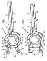
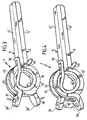
- Figures 1 to 4 are four in total with the reference numerals 1 to 4 provided clips shown each comprise three components, namely a first Clip half 6, a second clip half 8 and one Coil spring 10.
- Clip 1 has two elongated, rectangular clamping arms 12 and 14, which are essentially flat against one another issue.
- the clip half 8 goes in an end region the clamping arm 14 in a substantially circular bearing ring 16, whose axis of symmetry extends transversely to the longitudinal direction of the clamping arm 14.
- the Clamping arm 14 tapers in the area of the transition, so that the bearing ring 16 is somewhat thinner than the clamping arm 14 is wide.
- a second actuation projection crosses 28 the bearing shell 20 by also in an area is arranged on the bearing ring 16, which is is located between the two shell halves 22 and 24.
- the bearing shell 20 extends approximately over an angular range of 200 °
- the actuating projection 26 and the actuating projection 28 are located radially from the axis of symmetry of the clamping ring 16 pointing away and enclose an angle of approximately 40 °.
- the clip 1 is held together by the coil spring 10, whose outer diameter is essentially at the Inner diameter of the bearing ring 16 is adapted.
- Free end 30 of the coil spring 10 is in the screw direction tangential and is finally 90 ° angled into a on the bearing ring 16 to the axis of symmetry open recess 32 inserted.
- the other end the coil spring 10 is initially parallel at right angles angled to the clamping arm 14 and embraced the bearing ring 16 with a bearing on the clamping arm 12 U-shaped bend 34.
- the coil spring 10 In the closed state of clip 1, as shown in FIG. 1 is shown, the coil spring 10 is already under a certain tension, so that the one hand on the bearing ring 16 and on the other hand attacking the clamping arm 12 Coil spring 10, the two clamping arms 12 and 14 presses against each other.
- the coil spring 10 serves on the one hand as a bearing shaft on which the bearing ring 16 and the bearing shell 20 are mounted, wherein they have an axis of rotation defines the axis of symmetry of the bearing ring 16 and the coil spring 10 corresponds.
- Double crossed clip 1 is opened by on the actuating projections 26 and 28 one another opposing force is exerted, so that the actuating projections 26 and 28 to open the clip 1 be moved towards each other.
- the averted Side surfaces of the actuating projections 26 and 28 are with tool holders 36 in the form of hemispherical recesses Mistake.
- a not shown Application tool with spherical tool ends engage in the tool holders 36.
- the spherical design of the tool holder 36 and tool end is in each position of the clip 1 optimal power transmission possible.
- the clip 1 engages in the tool holders 36 Swivel tool ends around an axis, through the centers of the spherical tool ends runs. In this way, the application tool can be used open clip 1 and, if necessary, in Swing open position sideways.
- the clip 2 shown in Figure 2 differs from clip 1 essentially in that only the clamping arms 12 and 14 crossed as already described above are.
- the fastening protrusions 26 'and 28' are not crossed, d.
- the fastening projection 28 ' is on Bearing ring 16 arranged so that it is not between the Shell halves 22 and 24 of the bearing shell 20 protrude, which are only over an angular range of extends about 150 °.
- the fastening projections are 26 'and 28' substantially parallel arranged to each other and in the facing each other Surfaces tool holders 36 'also in the form of hemispherical Recesses arranged.
- the spherical tool ends of the application tool guided into the tool holders 36 'and from each other be swung away.
- the direction of operation with clip 2 is exactly the opposite of that with the clip 1.
- the clip 3 shown in Figure 3 has both uncrossed clamping arms 12 'and 14' as well as uncrossed actuating projections 26 'and 28 'on. Accordingly, the clamp arm 12 'over the two-part, the Shell halves 22 and 24 encompassing and extending over an angular range bearing shell 20 extending from approximately 150 ° with the actuating projection 26 'connected, the clamping arm 14' over the bearing ring 16 with the actuating projection 28 ', the transition from Clamp arm 14 'to the bearing ring 16 not between the shell halves 22 and 24 is provided, as is the case with clips 1 and 2.
- the bearing shaft is formed by the helical spring 10 ', which, however, has modified ends 38 and 40 with respect to the helical spring provided for the clips 1 and 2.
- the helical spring 10 ' is bent on one side, starting from a last helical turn, projecting obliquely in the direction of the clamping arm 12', runs in a short section substantially parallel to the clamping arm 12 ', is then angled at right angles to it and lies on the clamping arm 12' on the latter Clamping arm 14 'on the opposite side.
- the other end of the coil spring 10 ' is guided in an analogous manner from the other side around the bearing ring 16 and ends in a U-shaped end 40, with a web extending transversely to two parallel sections of the end 40 abutting the clamping arm 14'.
- the end 40 encompassing the bearing ring 16 secures the helical spring 10 ′ on the clip half 8 and the end 38 the clip half 6 on the clip half 8.
- the clip 4 shown in FIG. 4 differs from clip 3 in that it has crossed actuation projections 26 and 28, as is also the case with clip 1 are provided, d. H. the actuation projection 28 on the bearing ring 16 so arranged that he protrudes between the shell halves 22 and 24, the extend over an angular range of approximately 200 °.
- 26 and 28 are hemispherically recessed Tool holders 36 'arranged.
- the actuating projections 26 and 28th are pivoted away from each other, for example by that an application tool with spherical tool ends engages in the tool holders 36 'and this panned.
- the tool holders 36 and 36 ' can be like the clip 3 alternatively also in the form of hemispherical projections 37 are formed, which is a correspondingly hemispherical. tool end of the application tool required. In any case, however, would also be a ball head connection between application tool and tool holder realized.
- clips 1 to 4 Due to the elongated design of clips 1 to 4 use through endoscopic approaches is possible. It is important to mention that clips 1 to 4 can be opened do not have to be completely encompassed, it is sufficient only apply the application tool the tool holders 36 and 36 '.
- the clip opens when the Actuating projections 26 and 28 are moved towards each other as is the case with clips 1 and 3 of Is the case with an odd number of crossings the clip opens when the actuating projections 26 and 28 are moved away from each other.
Landscapes
- Health & Medical Sciences (AREA)
- Surgery (AREA)
- Life Sciences & Earth Sciences (AREA)
- Heart & Thoracic Surgery (AREA)
- Molecular Biology (AREA)
- Vascular Medicine (AREA)
- Engineering & Computer Science (AREA)
- Biomedical Technology (AREA)
- Reproductive Health (AREA)
- Medical Informatics (AREA)
- Nuclear Medicine, Radiotherapy & Molecular Imaging (AREA)
- Animal Behavior & Ethology (AREA)
- General Health & Medical Sciences (AREA)
- Public Health (AREA)
- Veterinary Medicine (AREA)
- Clamps And Clips (AREA)
- Surgical Instruments (AREA)
Claims (22)
- Pince chirurgicale (1), avec deux bras de serrage (12, 14) qui peuvent pivoter l'un par rapport à l'autre autour d'un axe de rotation, présentent dans une position de serrage une zone de serrage essentiellement en application mutuelle, et présentent chacun une extrémité libre et une extrémité pourvue d'un palier, un arbre commun définissant l'axe de rotation étant monté dans les deux paliers, et avec un élément tendeur (10) associé aux deux bras de serrage (12, 14) et les maintenant sous précontrainte dans la position de serrage, les paliers s'appuyant contre l'arbre et l'un des deux paliers (16, 20) comprenant une bague de palier (16) traversée par l'arbre (10), caractérisée en ce que l'arbre est formé par l'élément tendeur (10).
- Pince selon la revendication 1, caractérisée en ce que l'autre palier comprend un coussinet (20) qui n'entoure l'arbre (10) que partiellement en direction circonférentielle.
- Pince selon l'une des revendications précédentes, caractérisée en ce qu'un contre-appui (18) est prévu sur l'un des deux bras de serrage (6, 8), contre-appui contre lequel l'autre des deux bras de serrage (6, 8) s'appuie dans la direction de l'axe de rotation.
- Pince selon la revendication 3, caractérisée en ce que le contre-appui est formé par une saillie (18) disposée sur l'un des deux paliers (16, 20), saillie contre laquelle l'autre palier s'appuie au moins d'un côté dans la direction de l'axe de rotation.
- Pince selon l'une des revendications précédentes, caractérisée en ce que l'élément tendeur est formé par un ressort à boudin (10).
- Pince selon l'une des revendications précédentes, caractérisée en ce que l'élément tendeur (10) présente deux extrémités libres (30, 34 ; 38, 40), qui s'appuient respectivement contre un bras de serrage (6, 8).
- Pince selon la revendication 6, caractérisée en ce qu'au moins une des extrémités libres (30, 34 ; 38, 40) de l'élément tendeur (10) est coudée et s'appuie contre un des bras de serrage (6, 8) dans la région de la zone de serrage (12, 14), sur un côté opposé à la zone de serrage (12, 14).
- Pince selon la revendication 6 ou 7, caractérisée en ce qu'une autre extrémité libre (30, 34 ; 38, 40) de l'élément tendeur (10) est coudée et s'appuie contre l'autre bras de serrage (6, 8) dans la région de la zone de serrage (12, 14), sur un côté opposé à la zone de serrage (12, 14).
- Pince selon la revendication 6 ou 7, caractérisée en ce que l'autre extrémité libre (30) de l'élément tendeur (10) s'appuie contre un contre-appui (32) d'élément tendeur disposé sur un des deux paliers (16, 20).
- Pince selon la revendication 9, caractérisée en ce que le contre-appui (32) d'élément tendeur est disposé sur la bague de palier (16).
- Pince selon la revendication 9 ou 10, caractérisée en ce que le contre-appui d'élément tendeur est formé par un évidement (32).
- Pince selon l'une des revendications précédentes, caractérisée en ce que chacun des deux bras de serrage (6, 8) présente au moins un élément d'actionnement (26, 28) pour ouvrir la pince (1 ; ; 2 ; 3 ; 4).
- Pince selon la revendication 12, caractérisée en ce que les éléments d'actionnement (26, 28) sont disposés sur les paliers (16, 20).
- Pince selon la revendication 13, caractérisée en ce que les éléments d'actionnement (26, 28) sont disposés sur les paliers (16, 20) en étant sensiblement diamétralement opposés à la zone de serrage (12, 14).
- Pince selon la revendication 2 et la revendication 13 ou 14, caractérisée en ce qu'un des éléments d'actionnement (26, 28) est disposé dans une région terminale du coussinet (20).
- Pince selon les revendications 2 et 14, caractérisée en ce que l'élément d'actionnement (28) disposé sur l'autre bras de serrage (8) est disposé en dehors d'une région de la bague de palier (16) qui est délimitée par le coussinet (20).
- Pince selon les revendications 2 et 15, caractérisée en ce que l'élément d'actionnement (28) disposé sur l'autre bras de serrage (8) est disposé sur une région de la bague de palier (16) qui est délimitée par le coussinet (20).
- Pince selon l'une des revendications 12 à 17, caractérisée en ce qu'au moins un des éléments d'actionnement est formé par une saillie d'actionnement (26, 28).
- Pince selon l'une des revendications 12 à 18, caractérisée en ce que les éléments d'actionnement (26, 28) comprennent des éléments récepteurs d'outil (36, 37) qui présentent une surface sphérique.
- Pince selon la revendication 19, caractérisée en ce qu'au moins un des éléments récepteurs d'outil est formé par un évidement (36) essentiellement hémisphérique.
- Pince selon la revendication 19 ou 20, caractérisée en ce qu'au moins un des éléments récepteurs d'outil est formé par une saillie (37) essentiellement hémisphérique.
- Pince selon l'une des revendications précédentes, caractérisée en ce que les deux bras de serrage (6, 8) se croisent dans une région de transition entre la zone de serrage (12, 14) et les paliers (16, 20).
Applications Claiming Priority (3)
| Application Number | Priority Date | Filing Date | Title |
|---|---|---|---|
| DE19935418 | 1999-07-28 | ||
| DE19935418A DE19935418C5 (de) | 1999-07-28 | 1999-07-28 | Chirurgischer Clip |
| PCT/EP2000/006126 WO2001008568A1 (fr) | 1999-07-28 | 2000-06-30 | Pince chirurgicale |
Publications (2)
| Publication Number | Publication Date |
|---|---|
| EP1196094A1 EP1196094A1 (fr) | 2002-04-17 |
| EP1196094B1 true EP1196094B1 (fr) | 2003-01-02 |
Family
ID=7916338
Family Applications (1)
| Application Number | Title | Priority Date | Filing Date |
|---|---|---|---|
| EP00949232A Expired - Lifetime EP1196094B1 (fr) | 1999-07-28 | 2000-06-30 | Pince chirurgicale |
Country Status (5)
| Country | Link |
|---|---|
| US (1) | US20020111643A1 (fr) |
| EP (1) | EP1196094B1 (fr) |
| JP (1) | JP3577036B2 (fr) |
| DE (1) | DE19935418C5 (fr) |
| WO (1) | WO2001008568A1 (fr) |
Cited By (3)
| Publication number | Priority date | Publication date | Assignee | Title |
|---|---|---|---|---|
| DE102008031387A1 (de) | 2008-07-02 | 2010-01-07 | Medi-Globe Gmbh | Medizinischer Clip |
| DE102009036365A1 (de) | 2009-08-06 | 2011-02-10 | Norbert Lemke | Chirurgische Klammer sowie Vorrichtung zum intrakorporalen Einbringen der chirurgischen Klammer |
| US11311299B2 (en) | 2017-11-20 | 2022-04-26 | Aesculap Ag | Surgical clip with bracket-free guide system |
Families Citing this family (34)
| Publication number | Priority date | Publication date | Assignee | Title |
|---|---|---|---|---|
| FR2825262B1 (fr) * | 2001-06-01 | 2003-08-29 | Surgical Diffusion | Dispositif atraumatique pour interventions chirurgicales sur des organes du corps humain |
| US7634306B2 (en) * | 2002-02-13 | 2009-12-15 | Kinamed, Inc. | Non-image, computer assisted navigation system for joint replacement surgery with modular implant system |
| ATE463213T1 (de) * | 2002-08-09 | 2010-04-15 | Kinamed Inc | Nicht bildgebende ortungsverfahren für eine hüftoperation |
| US6945956B2 (en) | 2002-12-23 | 2005-09-20 | Medtronic, Inc. | Steerable catheter |
| DE10309491B8 (de) * | 2003-02-26 | 2005-09-08 | Aesculap Ag & Co. Kg | Chirurgischer Clip |
| AU2004220635A1 (en) * | 2003-03-06 | 2004-09-23 | Applied Medical Resources Corporation | Spring clip and method for assembling same |
| US20060265270A1 (en) * | 2005-05-23 | 2006-11-23 | Adam Hyder | Intelligent job matching system and method |
| US20080004637A1 (en) * | 2006-04-29 | 2008-01-03 | Klassen James B | Surgical clip, applicator and applicator methods |
| US20080251402A1 (en) * | 2007-04-12 | 2008-10-16 | Sophia Chiu | Wrench Base Structure |
| JP5401088B2 (ja) * | 2008-12-09 | 2014-01-29 | 株式会社アドバネクス | クリップ |
| DE102009003273B4 (de) * | 2009-05-20 | 2018-12-20 | Lazic Besitz GmbH & Co. KG | Aneurysma-Clip |
| JP3157486U (ja) * | 2009-12-04 | 2010-02-18 | 中村 正一 | 外科手術用クリップ |
| US20110224700A1 (en) * | 2010-03-09 | 2011-09-15 | Teleflex Medical Incorporated | Narrow Profile Surgical Ligation Clip |
| US10136898B2 (en) | 2010-03-09 | 2018-11-27 | Teleflex Medical Incorporated | Narrow profile surgical ligation clip |
| DE102010037468A1 (de) * | 2010-09-10 | 2012-03-15 | Aesculap Ag | Chirurgischer Clip |
| DE102010037949A1 (de) | 2010-10-04 | 2012-04-05 | Aesculap Ag | Chirurgischer Clip |
| EP2755578A2 (fr) | 2011-09-15 | 2014-07-23 | Teleflex Medical Incorporated | Applicateur de clip de ligature chirurgicale manuelle |
| DE102012211379A1 (de) * | 2012-06-29 | 2014-03-27 | Aesculap Ag | Chirurgischer Clip mit Innenfeder |
| US9901351B2 (en) | 2012-11-21 | 2018-02-27 | Atricure, Inc. | Occlusion clip |
| DE102013200127A1 (de) * | 2013-01-08 | 2014-07-10 | Peter Lazic Gmbh | Aneurysma-Clip |
| DE102013102178B4 (de) * | 2013-01-22 | 2016-08-25 | Medxpert Gmbh | Sternum-Osteosynthese-System |
| CN106102598B (zh) | 2013-11-21 | 2022-04-15 | 阿特瑞克尔公司 | 阻断夹 |
| EP2929843B1 (fr) * | 2014-04-10 | 2018-05-30 | Lazic Besitz GmbH & Co. KG | Clip chirurgical comprenant trois bras de serrage |
| US10881415B2 (en) | 2014-04-10 | 2021-01-05 | Peter Lazic Gmbh | Surgical clip with three clamping arms |
| DE102014114946A1 (de) | 2014-10-15 | 2016-04-21 | Aesculap Ag | Chirurgischer Clip nach Art eines Karabiner-Clips |
| HK1225937A1 (zh) | 2014-12-12 | 2017-09-22 | Atricure, Inc. | 封堵夹 |
| EP3461435B1 (fr) | 2017-09-28 | 2019-09-04 | Lazic Besitz GmbH & Co. KG | Pince chirurgicale en matériau plastique renforcé par des fibres en carbone |
| CN108720879A (zh) * | 2018-04-03 | 2018-11-02 | 李钊伦 | 一种腹腔镜下应用的腔静脉临时阻断装置 |
| JP6647648B1 (ja) * | 2019-08-19 | 2020-02-14 | 国立大学法人高知大学 | 開閉クリップ |
| DE102019212415A1 (de) | 2019-08-20 | 2021-02-25 | Conti Temic Microelectronic Gmbh | Verfahren zur Positionserkennung eines Busteilnehmers |
| CN114027920B (zh) * | 2021-12-17 | 2025-01-21 | 重庆医科大学附属口腔医院 | 一种便于取放的显微血管夹组件及其使用方法 |
| EP4445849A1 (fr) | 2023-04-14 | 2024-10-16 | Aesculap AG | Clip médical |
| WO2024229226A1 (fr) * | 2023-05-03 | 2024-11-07 | Edwards Lifesciences Corporation | Pinces avec coupleurs pour fermeture de l'appendice auriculaire gauche |
| EP4704727A1 (fr) * | 2023-05-03 | 2026-03-11 | Edwards Lifesciences Corporation | Systèmes, appareils et procédés pour agrafes pour fermeture d'appendice auriculaire gauche |
Family Cites Families (14)
| Publication number | Priority date | Publication date | Assignee | Title |
|---|---|---|---|---|
| US1589076A (en) * | 1925-04-14 | 1926-06-15 | William J Haskins | Clothespin |
| US3598125A (en) * | 1968-06-07 | 1971-08-10 | James J Cogley | Aneurism clamp |
| US3802437A (en) * | 1971-08-02 | 1974-04-09 | G Kees | Clip for blood vessel |
| DE2232866C3 (de) * | 1972-03-07 | 1980-10-02 | Dynamit Nobel Ag, 5210 Troisdorf | Lösbare Verbindung zwischen Geschoß und Treibladungshülse |
| US3805792A (en) * | 1972-04-24 | 1974-04-23 | J Cogley | Vascular clamp and forceps system |
| US3827438A (en) * | 1972-07-10 | 1974-08-06 | G Kees | Aneurysm clip |
| CH602085A5 (fr) * | 1975-11-04 | 1978-07-31 | Erem Sa | |
| DE2952618C2 (de) * | 1979-12-28 | 1986-01-16 | Springler-Tritt Chirurgische Nadeln Gmbh, 7893 Jestetten | Gefäßklemme für mikrochirurgische Zwecke |
| US4324248A (en) * | 1980-05-30 | 1982-04-13 | Metatech Corporation | Microsurgical clip |
| US4416266A (en) * | 1981-05-15 | 1983-11-22 | The United States Of America As Represented By The Administrator Of The National Aeronautics And Space Administration | Medical clip |
| US4932955A (en) * | 1984-06-29 | 1990-06-12 | Baxter International Inc. | Clip |
| DE8911948U1 (de) * | 1989-10-06 | 1989-12-14 | Zeppelin, Dieter von, Dipl.-Ing., 8023 Pullach | Klemme zum Abklemmen von Blutgefäßen oder Aneurysmen |
| WO1993018711A1 (fr) * | 1992-03-18 | 1993-09-30 | Izi Corporation | Systeme pour le marquage postchirurgical de specimens pathologiques bruts |
| DE29604518U1 (de) * | 1996-03-11 | 1996-05-09 | VON ZEPPELIN Chirurgische Instrumente GmbH, 82049 Pullach | Aneurysmenklemme |
-
1999
- 1999-07-28 DE DE19935418A patent/DE19935418C5/de not_active Expired - Fee Related
-
2000
- 2000-06-30 WO PCT/EP2000/006126 patent/WO2001008568A1/fr not_active Ceased
- 2000-06-30 JP JP2001513309A patent/JP3577036B2/ja not_active Expired - Fee Related
- 2000-06-30 EP EP00949232A patent/EP1196094B1/fr not_active Expired - Lifetime
-
2002
- 2002-01-15 US US10/053,245 patent/US20020111643A1/en not_active Abandoned
Cited By (3)
| Publication number | Priority date | Publication date | Assignee | Title |
|---|---|---|---|---|
| DE102008031387A1 (de) | 2008-07-02 | 2010-01-07 | Medi-Globe Gmbh | Medizinischer Clip |
| DE102009036365A1 (de) | 2009-08-06 | 2011-02-10 | Norbert Lemke | Chirurgische Klammer sowie Vorrichtung zum intrakorporalen Einbringen der chirurgischen Klammer |
| US11311299B2 (en) | 2017-11-20 | 2022-04-26 | Aesculap Ag | Surgical clip with bracket-free guide system |
Also Published As
| Publication number | Publication date |
|---|---|
| DE19935418C2 (de) | 2001-07-12 |
| EP1196094A1 (fr) | 2002-04-17 |
| DE19935418A1 (de) | 2001-02-08 |
| DE19935418C5 (de) | 2013-08-29 |
| US20020111643A1 (en) | 2002-08-15 |
| JP3577036B2 (ja) | 2004-10-13 |
| JP2003505183A (ja) | 2003-02-12 |
| WO2001008568A1 (fr) | 2001-02-08 |
Similar Documents
| Publication | Publication Date | Title |
|---|---|---|
| EP1196094B1 (fr) | Pince chirurgicale | |
| EP2613716B1 (fr) | Clip chirurgical | |
| EP0699419B1 (fr) | Fixateur ostéosynthétique | |
| EP0570675B1 (fr) | Pince pour la préhension et le maintien de tissus | |
| EP1400658A1 (fr) | Turbocompresseur | |
| EP1112034B1 (fr) | Dispositif de serrage pour une tete | |
| DE102021119528A1 (de) | Lagerungsanordnung einer Taumelscheibe in einem Lenkgetriebebauteil und chirurgisches Instrument | |
| WO2019007463A1 (fr) | Articulation | |
| EP1099900A1 (fr) | Support articulé | |
| DE102022105548A1 (de) | Luftleitvorrichtung einer Kraftfahrzeugkarosserie eines Kraftfahrzeugs | |
| DE102008061854A1 (de) | Scharnier | |
| DE69922444T2 (de) | Feder- Verriegelungsvorrichtung | |
| EP0929268B1 (fr) | Appareil dentaire a verin median | |
| DE102005011806B4 (de) | Flexible Auspressvorrichtung für Dämpfungsbuchsen einer Kraftfahrzeugachse | |
| EP2803326A1 (fr) | Arbre tubulaire flexible | |
| DE10291501T5 (de) | Lager für ein mechanisches Wälzübertragungselement | |
| DE10132712B4 (de) | Knochenschraube und Osteosynthesevorrichtung | |
| WO1987007688A1 (fr) | Systeme de fixation | |
| EP1827267A1 (fr) | Dispositif de fixation orthopedique, et systeme de fixation orthopedique | |
| DE29913168U1 (de) | Chirurgischer Clip | |
| EP1431604A1 (fr) | Joint universel avec élément de retenue. | |
| DE202004010423U1 (de) | Flexible Auspressvorrichtung für Dämpfungsbuchsen einer Kraftfahrzeugachse | |
| DE202019100579U1 (de) | Sichteinstellmechanismus | |
| DE10159037B4 (de) | Verstelleinrichtung für Kraftfahrzeugsitze | |
| DE9307622U1 (de) | Instrument für chirurgische Zwecke |
Legal Events
| Date | Code | Title | Description |
|---|---|---|---|
| PUAI | Public reference made under article 153(3) epc to a published international application that has entered the european phase |
Free format text: ORIGINAL CODE: 0009012 |
|
| 17P | Request for examination filed |
Effective date: 20020110 |
|
| AK | Designated contracting states |
Kind code of ref document: A1 Designated state(s): AT BE CH CY DE DK ES FI FR GB GR IE IT LI LU MC NL PT SE |
|
| GRAH | Despatch of communication of intention to grant a patent |
Free format text: ORIGINAL CODE: EPIDOS IGRA |
|
| GRAH | Despatch of communication of intention to grant a patent |
Free format text: ORIGINAL CODE: EPIDOS IGRA |
|
| GRAA | (expected) grant |
Free format text: ORIGINAL CODE: 0009210 |
|
| AK | Designated contracting states |
Kind code of ref document: B1 Designated state(s): FR GB IT |
|
| REG | Reference to a national code |
Ref country code: GB Ref legal event code: FG4D Free format text: 20030102:NOT ENGLISH |
|
| REG | Reference to a national code |
Ref country code: IE Ref legal event code: FG4D Free format text: GERMAN |
|
| GBT | Gb: translation of ep patent filed (gb section 77(6)(a)/1977) |
Effective date: 20030303 |
|
| ET | Fr: translation filed | ||
| REG | Reference to a national code |
Ref country code: IE Ref legal event code: FD4D Ref document number: 1196094E Country of ref document: IE |
|
| PLBE | No opposition filed within time limit |
Free format text: ORIGINAL CODE: 0009261 |
|
| STAA | Information on the status of an ep patent application or granted ep patent |
Free format text: STATUS: NO OPPOSITION FILED WITHIN TIME LIMIT |
|
| 26N | No opposition filed |
Effective date: 20031003 |
|
| PGFP | Annual fee paid to national office [announced via postgrant information from national office to epo] |
Ref country code: IT Payment date: 20140630 Year of fee payment: 15 |
|
| PG25 | Lapsed in a contracting state [announced via postgrant information from national office to epo] |
Ref country code: IT Free format text: LAPSE BECAUSE OF NON-PAYMENT OF DUE FEES Effective date: 20150630 |
|
| REG | Reference to a national code |
Ref country code: FR Ref legal event code: PLFP Year of fee payment: 17 |
|
| PGFP | Annual fee paid to national office [announced via postgrant information from national office to epo] |
Ref country code: FR Payment date: 20160621 Year of fee payment: 17 |
|
| PGFP | Annual fee paid to national office [announced via postgrant information from national office to epo] |
Ref country code: GB Payment date: 20170626 Year of fee payment: 18 |
|
| REG | Reference to a national code |
Ref country code: FR Ref legal event code: ST Effective date: 20180228 |
|
| PG25 | Lapsed in a contracting state [announced via postgrant information from national office to epo] |
Ref country code: FR Free format text: LAPSE BECAUSE OF NON-PAYMENT OF DUE FEES Effective date: 20170630 |
|
| GBPC | Gb: european patent ceased through non-payment of renewal fee |
Effective date: 20180630 |
|
| PG25 | Lapsed in a contracting state [announced via postgrant information from national office to epo] |
Ref country code: GB Free format text: LAPSE BECAUSE OF NON-PAYMENT OF DUE FEES Effective date: 20180630 |