EP1197362B1 - Dispositif de suspension comportant un vérin électrique et un ressort en parallèle - Google Patents
Dispositif de suspension comportant un vérin électrique et un ressort en parallèle Download PDFInfo
- Publication number
- EP1197362B1 EP1197362B1 EP01123564A EP01123564A EP1197362B1 EP 1197362 B1 EP1197362 B1 EP 1197362B1 EP 01123564 A EP01123564 A EP 01123564A EP 01123564 A EP01123564 A EP 01123564A EP 1197362 B1 EP1197362 B1 EP 1197362B1
- Authority
- EP
- European Patent Office
- Prior art keywords
- suspended mass
- vehicle
- suspended
- mass
- spring
- Prior art date
- Legal status (The legal status is an assumption and is not a legal conclusion. Google has not performed a legal analysis and makes no representation as to the accuracy of the status listed.)
- Expired - Lifetime
Links
- 239000000725 suspension Substances 0.000 title claims abstract description 38
- 230000001133 acceleration Effects 0.000 claims abstract description 14
- 238000013016 damping Methods 0.000 claims abstract description 10
- 230000002441 reversible effect Effects 0.000 claims abstract description 3
- 238000012937 correction Methods 0.000 claims description 45
- 238000005096 rolling process Methods 0.000 claims description 5
- 238000012935 Averaging Methods 0.000 claims description 2
- 230000001360 synchronised effect Effects 0.000 claims description 2
- 238000005259 measurement Methods 0.000 claims 1
- 238000006073 displacement reaction Methods 0.000 description 14
- 230000010355 oscillation Effects 0.000 description 7
- 230000000694 effects Effects 0.000 description 6
- 238000006243 chemical reaction Methods 0.000 description 4
- 230000006978 adaptation Effects 0.000 description 3
- 230000002349 favourable effect Effects 0.000 description 3
- 210000000056 organ Anatomy 0.000 description 3
- 239000006096 absorbing agent Substances 0.000 description 2
- 238000009825 accumulation Methods 0.000 description 2
- 238000010276 construction Methods 0.000 description 2
- 238000011161 development Methods 0.000 description 2
- 230000018109 developmental process Effects 0.000 description 2
- 238000010586 diagram Methods 0.000 description 2
- 230000005484 gravity Effects 0.000 description 2
- 230000000670 limiting effect Effects 0.000 description 2
- 238000012423 maintenance Methods 0.000 description 2
- 230000035939 shock Effects 0.000 description 2
- 230000006641 stabilisation Effects 0.000 description 2
- 238000011105 stabilization Methods 0.000 description 2
- 230000003068 static effect Effects 0.000 description 2
- 238000013459 approach Methods 0.000 description 1
- 230000002238 attenuated effect Effects 0.000 description 1
- 230000033228 biological regulation Effects 0.000 description 1
- 230000006835 compression Effects 0.000 description 1
- 238000007906 compression Methods 0.000 description 1
- 230000008094 contradictory effect Effects 0.000 description 1
- 238000011217 control strategy Methods 0.000 description 1
- 230000000593 degrading effect Effects 0.000 description 1
- 238000013461 design Methods 0.000 description 1
- 238000001514 detection method Methods 0.000 description 1
- 230000001627 detrimental effect Effects 0.000 description 1
- 238000002513 implantation Methods 0.000 description 1
- 230000002829 reductive effect Effects 0.000 description 1
- 238000005070 sampling Methods 0.000 description 1
Images




Classifications
-
- B—PERFORMING OPERATIONS; TRANSPORTING
- B60—VEHICLES IN GENERAL
- B60G—VEHICLE SUSPENSION ARRANGEMENTS
- B60G17/00—Resilient suspensions having means for adjusting the spring or vibration-damper characteristics, for regulating the distance between a supporting surface and a sprung part of vehicle or for locking suspension during use to meet varying vehicular or surface conditions, e.g. due to speed or load
- B60G17/02—Spring characteristics, e.g. mechanical springs and mechanical adjusting means
- B60G17/021—Spring characteristics, e.g. mechanical springs and mechanical adjusting means the mechanical spring being a coil spring
-
- B—PERFORMING OPERATIONS; TRANSPORTING
- B60—VEHICLES IN GENERAL
- B60G—VEHICLE SUSPENSION ARRANGEMENTS
- B60G17/00—Resilient suspensions having means for adjusting the spring or vibration-damper characteristics, for regulating the distance between a supporting surface and a sprung part of vehicle or for locking suspension during use to meet varying vehicular or surface conditions, e.g. due to speed or load
- B60G17/015—Resilient suspensions having means for adjusting the spring or vibration-damper characteristics, for regulating the distance between a supporting surface and a sprung part of vehicle or for locking suspension during use to meet varying vehicular or surface conditions, e.g. due to speed or load the regulating means comprising electric or electronic elements
- B60G17/0152—Resilient suspensions having means for adjusting the spring or vibration-damper characteristics, for regulating the distance between a supporting surface and a sprung part of vehicle or for locking suspension during use to meet varying vehicular or surface conditions, e.g. due to speed or load the regulating means comprising electric or electronic elements characterised by the action on a particular type of suspension unit
- B60G17/0157—Resilient suspensions having means for adjusting the spring or vibration-damper characteristics, for regulating the distance between a supporting surface and a sprung part of vehicle or for locking suspension during use to meet varying vehicular or surface conditions, e.g. due to speed or load the regulating means comprising electric or electronic elements characterised by the action on a particular type of suspension unit non-fluid unit, e.g. electric motor
-
- B—PERFORMING OPERATIONS; TRANSPORTING
- B60—VEHICLES IN GENERAL
- B60G—VEHICLE SUSPENSION ARRANGEMENTS
- B60G2202/00—Indexing codes relating to the type of spring, damper or actuator
- B60G2202/10—Type of spring
- B60G2202/12—Wound spring
-
- B—PERFORMING OPERATIONS; TRANSPORTING
- B60—VEHICLES IN GENERAL
- B60G—VEHICLE SUSPENSION ARRANGEMENTS
- B60G2202/00—Indexing codes relating to the type of spring, damper or actuator
- B60G2202/40—Type of actuator
- B60G2202/42—Electric actuator
- B60G2202/422—Linear motor
-
- B—PERFORMING OPERATIONS; TRANSPORTING
- B60—VEHICLES IN GENERAL
- B60G—VEHICLE SUSPENSION ARRANGEMENTS
- B60G2400/00—Indexing codes relating to detected, measured or calculated conditions or factors
- B60G2400/25—Stroke; Height; Displacement
- B60G2400/252—Stroke; Height; Displacement vertical
-
- B—PERFORMING OPERATIONS; TRANSPORTING
- B60—VEHICLES IN GENERAL
- B60G—VEHICLE SUSPENSION ARRANGEMENTS
- B60G2500/00—Indexing codes relating to the regulated action or device
- B60G2500/10—Damping action or damper
-
- B—PERFORMING OPERATIONS; TRANSPORTING
- B60—VEHICLES IN GENERAL
- B60G—VEHICLE SUSPENSION ARRANGEMENTS
- B60G2500/00—Indexing codes relating to the regulated action or device
- B60G2500/30—Height or ground clearance
-
- B—PERFORMING OPERATIONS; TRANSPORTING
- B60—VEHICLES IN GENERAL
- B60G—VEHICLE SUSPENSION ARRANGEMENTS
- B60G2600/00—Indexing codes relating to particular elements, systems or processes used on suspension systems or suspension control systems
- B60G2600/18—Automatic control means
- B60G2600/182—Active control means
Definitions
- the present invention relates to the field of suspensions.
- it relates to the suspension of vehicles, for example passenger cars. More specifically, it relates the means used to allow the travel between two points (a suspended point, for example linked to the body or chassis of a car, i.e. to the suspended mass, and a point unsprung, for example secured to a suspension arm or a wheel carrier, i.e. integral with the unsprung mass) while endeavoring to reduce variations in force developed by the suspension, seen by the suspended point.
- a suspended point for example linked to the body or chassis of a car, i.e. to the suspended mass
- a point unsprung for example secured to a suspension arm or a wheel carrier, i.e. integral with the unsprung mass
- EP 0 878 333 describes a suspension device according to the preamble of the claim 1.
- the suspension of a vehicle has constructive provisions by which the movement of a wheel or wheels of an axle is guided relative to the body (or by relation to the chassis if the vehicle is fitted with one, or between the body and the chassis if necessary), and it includes means controlling the travel of each wheel (a wheel is an organ says “not suspended") in relation to the body (any point on the body is said to be “suspended”), to carry the load while maintaining a certain ground clearance of the vehicle (this is the function spring) and to prevent maintenance of oscillations occurring between suspended and non-suspended points suspended following a disturbance (this is the function of a shock absorber).
- a spring is calculated to support the load of the vehicle while maintaining ground clearance sufficient for the vehicle. Thanks to the damping function, the wheels fitted with pneumatic tires tend to always remain in contact with the road when the suspension is requested by road irregularities. A damper prevents the maintenance of oscillations occurring as a result a disturbance, in particular the oscillations of the wheel itself, that the tire cannot alone mitigate quickly enough.
- This operating mode is useful in particular for absorbing the tire vibrations. It is proposed to detect the occurrence of a resonance of the tire for quickly give to a value sufficiently lower than 1 (for example according to a law of linear variation as a function of the amplitude) in order to dampen the vibrations of the mass not suspended.
- the objective of the invention is to propose another approach, making it much less useful to detection of an unsprung mass resonance, to provide a high level of safety vehicle operation and great comfort.
- the invention provides a suspension device, ensuring the control of the vertical clearance between a suspended mass and an unsprung mass, comprising an elastic connection mounted between the suspended mass and the unsprung mass, said elastic connection comprising a spring and comprising a jack reversible electric, acting in parallel with the spring to control the movements of relative movement between suspended mass and unsprung mass, Z cr being the distance between the suspended mass and the unsprung mass, said device comprising means for controlling the electric jack for, from an observed variation of the distance Z cr between the suspended mass and the unsprung mass, due to a deflection of the elastic connection, that the electric jack develops a force F.
- roller assembly means the totality of the organs which, for a given suspension configuration, usually stored in the unsprung mass.
- the unsprung mass comprises, in addition to all the members rotating around the axis of rotation of the wheel, the wheel holder, the bar, the brake caliper and the electric traction motor (the suspension motor does not not part).
- the invention proposes to develop a force component in the electric actuator which takes into account the unsprung mass, which tends to prevent the accumulation of energy in this one.
- the electric actuator is controlled so as to develop an accompanying component of the spring, creating an oriented force such as the relative displacement between body and wheel, so as to erase the variations in force due to the variations in clearance.
- the role of the electric actuator is to limit as much as possible the variations in force seen by the checkout. If there was no variation in effort, there would be no acceleration, so no cash movement vertically, so the comfort would be very great.
- the electric actuator acts in permanently in spring corrector in order to radically limit variations in force than otherwise the spring would impose on the mass suspended under the action of external disturbances, while preventing an unacceptable accumulation of energy in the unsprung mass.
- Function of this spring corrector consists in modifying the reaction force that would naturally have developed the spring in response to a disturbance, applying a correction strategy aiming to provide the best possible comfort while preserving security.
- FIG. 1 in front view a four-wheeled passenger vehicle, equipped with connections elastics 1 mounted between the wheels 2 and the body 3.
- FIG 2 the four connections elastic 1 mounted between the wheels 2 and the body 3 of the vehicle.
- Each elastic link comprises a vertical slide 7, a helical spring 4 and an electric actuator 5 mounted in parallel.
- the electric actuator 5 comprises a rack 50 secured to the unsprung part of the ground connection.
- An electric motor 52 is fixed by its carcass to the suspended part of the ground connection.
- a pinion 51 is mounted on the rotor of the motor and is meshed on the rack 50.
- patent application EP 0 878 332 For more details on a possible construction including guiding the wheel plane by a vertical slide, consult patent application EP 0 878 332.
- other principles for linking a rolling assembly to a body can be adopted and are compatible with the use of an electric cylinder and a spring mounted in parallel.
- the body 3 shown in solid lines is not rolled. It’s its natural look driving in a straight line.
- the 3 ′ body on the other hand, has slight roll overcompensation and we will come back to this aspect in more detail below.
- an electric motor 52 of the self-controlled synchronous type is used, permanent magnets.
- This type of engine by construction includes position sensors of the rotor used to control it, whatever the application. Used in this application, these sensors actually measure the variation in distance between the wheel 2 and the body 3. The information coming from the sensors internal to the engine reaches a control unit 55 individual wheel, via channels 53.
- the effort F therefore comprises a mass compensation component weighted by the coefficient C a , a damping component weighted by the coefficient C v and a spring support component weighted by the coefficient C p .
- the coefficients can be chosen experimentally according to the starting values which are proposed below.
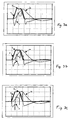
- Figures 3a to 5c show the effect of the different components.
- the road profile is shown, which is equivalent to the variation (on the ordinate) of the ground level as a function of time (on the abscissa) if it is assumed that the vehicle is traveling at constant speed. It is the curve "P".
- the horizontal axis represents a reference determined by the average level of the road.
- the ordinates are the deviations from this average level.
- the road profile therefore comprises a first level without deviation from the average level, followed by a bump with a trapezoidal profile, followed by a second level without deviation from the average level. All the figures relate to the crossing of the same obstacle, namely an elevation of the ground level followed by a return to the initial level (an isolated bump).
- the curve “Z r ” shows the displacement of the wheel (that is to say of the unsprung mass) which results from the crossing of the obstacle for a suspension having the characteristics illustrated respectively by each of the figures.
- the curve “Z c ” illustrates the displacement of the body, that is to say of the suspended mass, which results from the crossing of the obstacle for a suspension having the characteristics illustrated respectively by each of the figures.
- the curve “F” illustrates the evolution of the force in the electric actuator 5 which results from crossing the obstacle for a suspension having the characteristics illustrated respectively by each of the figures.
- FIGS. 3a, 3b and 3c illustrate the effect of the compensation of the unsprung mass by a variation of the coefficient C a , the coefficients C v and C p having constant values.
- the coefficient C a is zero in Figure 3a.
- interesting performance has been observed by compensating up to about 50% of the unsprung mass.
- the intermediate value in Figure 3b corresponds to a compensation of approximately 30% of the unsprung mass.
- the value in Figure 3c corresponds to a compensation of approximately 70% of the unsprung mass.
- the disturbance imposed by the profile of the road and the force reaction F result in a displacement of the unsprung mass illustrated by the curve Z r , and a displacement of the body illustrated by the curve Z c .
- Figures 4a, 4b and 4c illustrate the effect of damping by varying the coefficient C v , the coefficients C a and C p having constant values.
- the coefficient C v is low in Figure 4a, is of intermediate value in Figure 4b, and higher in Figure 4c.
- To choose an initial value of C v we give our the criterion that the amplitude of the second oscillation is attenuated by 90% compared to the amplitude of the first. It can be seen by the curves F that it is established in the electric actuator 5 an effort that is all the greater as the damping is increased.
- Figures 5a, 5b and 5c illustrate the effect of spring compensation by modifying its apparent stiffness as explained in patent application EP 0 878 333, by a variation of the coefficient C p , the coefficients C a and C v having constant values.
- the coefficient C p is zero in Figure 5a.
- the coefficient C p is equal to 1 when the electric actuator operates as a pure profile follower, in the sense given to this expression in the aforementioned patent. This coefficient is not chosen independently of the jurisdiction. The more you choose a stiff spring, the more weight should be given to this component if you want to preserve comfort. Interesting performances have been observed up to about 80% of behavior in pure profile follower.
- the coefficient is 0.4 in Figure 5b and 0.8 in Figure 5c.
- Figures 3b (configurations identical to Figures 4b and 5b) and 5c illustrate good combinations of coefficient values. It is however difficult to propose combinations of universal value. It is advisable to proceed experimentally in order to choose which is best for a given vehicle. But unlike suspensions Conventional, the search for the best solution is done here by simple programming. he is therefore much faster, more efficient and more economical to sweep a large number of combinations of features because there are no mechanical parts to change.
- the control unit 55 receives from the sensors internal to the engine, via the channel 53, information on the instantaneous measured position "Z im " of the electric actuator (see FIG. 6).
- a function block 70 of the unit 55 continuously recalculates the equilibrium position, designated by Z o , in which the force of the spring 4 exactly compensates for the static load of the body.
- the unit 55 continuously calculates the force F to be exerted, according to a predetermined sampling period (for example every milliseconds). During successive calculations, the unit 55 gradually adapts the force of the electric actuator to the deflection deviations having a permanent character, in order to progressively cancel the correction due to these. This is what provides some relaxation.
- a function block 71 calculates the value of F as explained above, taking into account the choices made for the coefficients .
- the suspension device comprises means for evaluating such a stress, not vertical and oriented parallel to the right joining the centers of the contact areas on the ground of the wheels considered, here belonging to an axle since the roll. We oppose this phenomenon by developing in the electric cylinders 5 a correction component + C 1 outside the turn and -C 1 inside the turn. By playing on the amplitude of this correction, one can limit the roll angle, or even over-compensate it as shown by the body 3 'shown in broken lines.
- the roll and pitch are referred to indistinctly below as "attitude variation”.
- a component F 4 for attitude correction is added.
- the steering is programmed so as to create a correction torque of plate which opposes the roll.
- the steering is programmed so as to create an attitude correction torque which controls the pitch.
- the invention applies to a vehicle comprising at least four connections to the ground forming a front axle and a rear axle, the steering being programmed so as to create an attitude correction torque which controls both the roll and pitching.
- the steering of the attitude correction components is centralized because it concerns globally balance of the vehicle. It is provided by a central unit 6.
- the central unit 6 ensures at least a roll correction.
- the central unit 6 can also provide or ensure a pitch correction of the vehicle.
- each of the said links to the ground is likely to receive means for controlling the electric cylinders a force instruction which is the result of a contribution for the correction of the roll and a contribution for the pitch correction.
- the global correction component trim is the algebraic sum of a roll contribution and a contribution relating to the pitch.
- the correction components are of equal absolute value and are oriented in opposite directions one on the other side and on the other side of the vehicle.
- Said roll correction components are absolute value equal and being oriented in opposite directions from each other in each axle (a axle constituting a group of links to the ground), in order to apply to the body 3 a torque antiroll.
- Roll can be partially compensated (lower energy expenditure), or totally (better comfort, better tire performance), or even can be overcompensated as mentioned above, to improve the functioning even more radically of a vehicle like a four-wheel passenger car.
- the higher the compensation important the more you have to be able to develop a significant torque in the 52 motors, and to maintain it the time that the transverse (or longitudinal) stresses last, these being much longer than the stresses coming from the bumpy nature of the road, calling the depreciation component which will be discussed below.
- sensors 61, 62, 63 such as for example accelerometers linked to the body to assess non-vertical stress. It can be transverse acceleration and / or yaw speed (resulting in roll). We can also assess the acceleration longitudinal (resulting in pitch). This or these assessments allow develop one or more correct attitude correction couples.
- sensors making it possible to evaluate parameters indicative of the driving conditions. It is for example a steering wheel angle, pressure sensor brakes, accelerator action, and a vehicle speed sensor. This can allow to anticipate with respect to the moment at which accelerations parallel to the ground appear (transverse, longitudinal acceleration). In this case, we can use steering strategies observing those of the pilot's actions, estimating the likely consequences on the roll (and on the pitch), and the appropriate attitude correction is determined.
- control means can be controlled so that a torque overcompensating for transverse acceleration is accompanied by a slight dive vehicle volunteer.
- This example is cited only to make it clear that there is an infinity active controls possible.
- the invention also makes it possible to control in real time and very easily the distribution between the front axle and the rear axle of said roll correction components.
- an overall anti-roll torque acting on the body, plus the correction share of roll provided by the rear axle is important, the more the vehicle will tend towards a behavior survivor, and vice versa.
- ESP stabilization effect
- a stabilization effect can be obtained by acting dynamically on the distribution of roll correction torque between the front and the rear of the vehicle.
- the invention therefore applies, in a particular embodiment, to a vehicle comprising at least one front axle and one rear axle each having two connections to the ground mounted on either side of the median plane of symmetry of the vehicle, said means of steering steering in real time the distribution between the front axle and the rear axle of said attitude correction components opposing roll.
- the pitch correction of a 4-wheel passenger vehicle body depends on a overall pitch correction torque, and we can distribute on either side of the plane of symmetry of the vehicle, possibly by real-time control, the correction components acting on the pitch.
- the invention therefore applies, in a particular embodiment, to a vehicle comprising at least one front axle and one rear axle each having two connections on the ground mounted on either side of the median plane of symmetry of the vehicle, said means of steering driving in real time the distribution on either side of the median plane of symmetry of the vehicle of said correction components acting on the pitch.
Landscapes
- Engineering & Computer Science (AREA)
- Mechanical Engineering (AREA)
- Vehicle Body Suspensions (AREA)
- Vibration Prevention Devices (AREA)
- Fluid-Damping Devices (AREA)
Description
- la figure 1 montre un véhicule équipé d'une suspension selon l'invention,
- la figure 2 est un schéma d'implantation sur un véhicule des principaux éléments de l'invention,
- les figures 3a, 3b et 3c illustrent, en fonction du temps et en synchronisme, l'évolution du profil de la route, cause de la sollicitation de la suspension, le déplacement de la masse non suspendue qui en résulte, le déplacement de la masse suspendue qui en résulte, et l'évolution de l'effort dans le vérin électrique, pour plusieurs combinaisons des coefficients Ca, Cv et Cp, dans lesquelles on augmente progressivement Ca en passant de la figure 3a à la figure 3c, Cv et Cp étant constants.
- les figures 4a, 4b et 4c illustrent les mêmes évolutions pour d'autres combinaisons des coefficients Ca, Cv et Cp, dans lesquelles on augmente progressivement Cv en passant de la figure 4a à la figure 4c, Ca et Cp étant constants
- les figures Sa, 5b et 5c illustrent les mêmes évolutions pour d'autres combinaisons des coefficients Ca, Cv et Cp, dans lesquelles on augmente progressivement Cp en passant de la figure 5a à la figure 5c, Cv et Ca étant constants
- la figure 6 représente l'invention sous la forme d'un schéma bloc.
Claims (12)
- Dispositif de suspension d'un véhicule, assurant le contrôle du débattement vertical entre une masse suspendue et une masse non suspendue, comportant une liaison élastique (1) montée entre la masse suspendue et la masse non suspendue, ladite liaison élastique (1) comprenant un ressort (4) et comportant un vérin électrique (5) réversible, agissant en parallèle du ressort (4) pour contrôler les mouvements de débattement relatif entre masse suspendue et masse non suspendue, Zcr étant la distance entre un point de la masse suspendue et un point de la masse non suspendue, ledit dispositif comportant des moyens de pilotage du vérin électrique pour, à partir d'une variation observée de la distance Zcr, due à un débattement de la liaison élastique, que le vérin électrique développe un effort F caractérisé en ce que l'effort F est une composante de compensation de masse F1 = Ca.Mr.Acr orientée comme l'accélération Acr du débattement de la masse non suspendue par rapport à la masse suspendue, avec Mr étant la masse non suspendue et Ca un coefficient, ainsi qu'une composante d'amortissement F2 = -Cv.Vcr s'opposant à la vitesse Vcr dudit débattement, Cv étant un coefficient.
- Dispositif selon la revendication 1 dans lequel le vérin électrique est piloté par lesdits moyens de pilotage de façon à ce qu'il développe un effort F ayant en outre une composante d'accompagnement de ressort F3 = Cp.K.Zcr, orientée à l'inverse de la variation de force développée par le ressort et due à la variation de la distance Zcr causée par ledit débattement, K étant la raideur du ressort et Cp un coefficient.
- Dispositif selon l'une des revendications 1 ou 2, dans lequel la valeur des coefficients est adaptée en temps réel en fonction de paramètres indicateurs des conditions de conduite du véhicule.
- Dispositif de suspension selon l'une des revendications 1 à 3 dans lequel l'unité (55) calcule une position d'équilibre Zo pour la distance entre la masse suspendue et la masse non suspendue, dans laquelle l'effort du ressort (4) compense exactement la masse suspendue en moyennant la valeur absolue instantanée Zim de la position relative de la masse non suspendue par rapport à la masse suspendue, et recalcule Zcr = Zim - Zo.
- Dispositif selon l'une des revendications 1 à 4, dans lequel le vérin électrique (5) comporte un moteur électrique (52) de type synchrone auto piloté, à aimants permanents, et dans lequel les moyens de pilotage déterminent la variation de la position relative entre point suspendu et point non suspendu entièrement à partir d'une mesure de la variation de position délivrée par les capteurs intégrés au moteur électrique.
- Dispositif de suspension globale d'un véhicule comportant une masse suspendue et au moins un groupe de deux liaisons au sol comportant un dispositif de suspension selon l'une des revendications 1 à 5, dans lequel les vérins électriques sont pilotés par lesdits moyens de pilotage de façon à ce qu'ils développent un effort F ayant en outre une composante de correction d'assiette F4, ladite composante de correction d'assiette appliquant à ladite caisse un couple de correction d'assiette.
- Dispositif selon la revendication 6 dans lequel les moyens de pilotage comportent des moyens pour évaluer une sollicitation non verticale appliquée à la masse suspendue et susceptible de provoquer une variation d'assiette de la masse suspendue et pour calculer la composante de correction d'assiette.
- Dispositif selon la revendication 7, dans lequel lesdites au moins deux liaisons au sol forment un essieu, lesdites liaisons au sol étant montées de part et d'autre du plan médian de symétrie du véhicule, de sorte que ledit couple de correction d'assiette s'oppose au roulis.
- Dispositif selon la revendication 7, dans lequel lesdites au moins deux liaisons au sol comportent une liaison au sol avant et une liaison au sol arrière, de sorte que ledit couple de correction d'assiette s'oppose au tangage.
- Dispositif selon la revendication 7, pour un véhicule comportant au moins quatre liaisons au sol formant un essieu avant et un essieu arrière, dans lequel ledit couple de correction d'assiette s'oppose à la fois au roulis et au tangage.
- Dispositif selon l'une des revendications 7 à 10, pour un véhicule comportant au moins un essieu avant et un essieu arrière ayant chacun deux liaisons au sol montées de part et d'autre du plan médian de symétrie du véhicule, lesdits moyens de pilotage pilotant en temps réel la répartition entre l'essieu avant et l'essieu arrière desdites composantes de correction d'assiette s'opposant au roulis.
- Dispositif selon l'une des revendications 7 à 11, pour un véhicule comportant au moins un essieu avant et un essieu arrière ayant chacun deux liaisons au sol montées de part et d'autre du plan médian de symétrie du véhicule, lesdits moyens de pilotage pilotant en temps réel la répartition de part et d'autre du plan médian de symétrie du véhicule desdites composantes de correction s'opposant au tangage.
Applications Claiming Priority (2)
| Application Number | Priority Date | Filing Date | Title |
|---|---|---|---|
| FR0013106A FR2814985A1 (fr) | 2000-10-11 | 2000-10-11 | Dispositif de suspension comportant un verin electrique et un ressort en parallele |
| FR0013106 | 2000-10-11 |
Publications (2)
| Publication Number | Publication Date |
|---|---|
| EP1197362A1 EP1197362A1 (fr) | 2002-04-17 |
| EP1197362B1 true EP1197362B1 (fr) | 2004-03-17 |
Family
ID=8855302
Family Applications (1)
| Application Number | Title | Priority Date | Filing Date |
|---|---|---|---|
| EP01123564A Expired - Lifetime EP1197362B1 (fr) | 2000-10-11 | 2001-10-01 | Dispositif de suspension comportant un vérin électrique et un ressort en parallèle |
Country Status (7)
| Country | Link |
|---|---|
| US (1) | US6708094B2 (fr) |
| EP (1) | EP1197362B1 (fr) |
| JP (1) | JP2002192931A (fr) |
| AT (1) | ATE261827T1 (fr) |
| BR (1) | BR0104496A (fr) |
| DE (1) | DE60102335T2 (fr) |
| FR (1) | FR2814985A1 (fr) |
Families Citing this family (29)
| Publication number | Priority date | Publication date | Assignee | Title |
|---|---|---|---|---|
| JP3722127B2 (ja) | 2003-02-05 | 2005-11-30 | 日産自動車株式会社 | 車両用電磁サスペンション装置 |
| JP3722128B2 (ja) * | 2003-02-05 | 2005-11-30 | 日産自動車株式会社 | 車両用電磁サスペンション装置と車両用電磁サスペンション装置のモータ制御方法 |
| US7150340B2 (en) * | 2003-02-21 | 2006-12-19 | Lockheed Martin Corporation | Hub drive and method of using same |
| US20040231904A1 (en) * | 2003-02-21 | 2004-11-25 | Beck Michael S. | System and method for actively controlling traction in an articulated vehicle |
| US8839891B2 (en) * | 2003-02-21 | 2014-09-23 | Lockheed Martin Corporation | Multi-mode skid steering |
| US20050023052A1 (en) * | 2003-02-21 | 2005-02-03 | Beck Michael S. | Vehicle having an articulated suspension and method of using same |
| US7464775B2 (en) * | 2003-02-21 | 2008-12-16 | Lockheed Martin Corporation | Payload module for mobility assist |
| US20040232632A1 (en) * | 2003-02-21 | 2004-11-25 | Beck Michael S. | System and method for dynamically controlling the stability of an articulated vehicle |
| JP2004306733A (ja) * | 2003-04-04 | 2004-11-04 | Hitachi Ltd | 車両用懸架装置、車体姿勢制御方法及びその装置 |
| EP1552970A1 (fr) * | 2004-01-07 | 2005-07-13 | Delphi Technologies, Inc. | Dispositif de suspension à force réglable |
| JP2005262946A (ja) * | 2004-03-17 | 2005-09-29 | Aisin Seiki Co Ltd | スタビライザ制御装置 |
| DE102005060504B3 (de) * | 2005-12-17 | 2007-04-05 | Zf Friedrichshafen Ag | Niveauregulierung |
| JP4525651B2 (ja) * | 2006-09-15 | 2010-08-18 | トヨタ自動車株式会社 | 車両用サスペンションシステム |
| US7740046B2 (en) | 2007-04-27 | 2010-06-22 | Won-Door Corporation | Method, apparatus and system for controlling a movable partition |
| US8087444B2 (en) | 2006-11-03 | 2012-01-03 | Won-Door Corporation | Movable partitions with lateral restraint devices and related methods |
| WO2008058031A2 (fr) * | 2006-11-03 | 2008-05-15 | Won-Door Corporation | Cloisons mobiles à dispositifs de retenue latérale et procédés associés |
| US7926538B2 (en) * | 2007-01-11 | 2011-04-19 | Won-Door Corporation | Lateral restraint for a movable partition, movable partitions incorporating same and related methods |
| JP5171594B2 (ja) * | 2008-12-15 | 2013-03-27 | 日立建機株式会社 | 電動車両及びそのピッチング制御装置 |
| JP5319587B2 (ja) * | 2010-03-25 | 2013-10-16 | ニチユ三菱フォークリフト株式会社 | 産業車両 |
| US9074420B2 (en) | 2011-05-31 | 2015-07-07 | Won-Door Corporation | Methods, apparatuses, and systems for resisting lateral displacement of movable partitions |
| US8960257B2 (en) | 2011-05-31 | 2015-02-24 | Won-Door Corporation | Methods, apparatuses, and systems for controlling lateral displacement of a movable partition |
| WO2013052540A2 (fr) * | 2011-10-04 | 2013-04-11 | Parker-Hannifin Corporation | Procédé et système permettant de commander des actionneurs électriques |
| US9428242B2 (en) | 2014-02-24 | 2016-08-30 | Harley-Davidson Motor Company Group, LLC | Variable ride height systems and methods |
| US9068616B1 (en) | 2014-02-28 | 2015-06-30 | GM Global Technology Operations LLC | Vehicle suspension system |
| CN105644295B (zh) * | 2016-03-07 | 2017-11-17 | 江苏大学 | 一种主动液压互联式馈能悬架 |
| US11511589B2 (en) * | 2018-08-20 | 2022-11-29 | Rassini Suspensiones, S.A. De C.V. | Adjustable suspension mount assembly |
| CN109334374B (zh) * | 2018-10-12 | 2020-11-06 | 汤在英 | 一种电机驱动的变矩悬架 |
| CN111301088B (zh) * | 2019-12-02 | 2023-04-07 | 西安科技大学 | 一种复合阻尼可调式馈能型混合悬架作动器及控制方法 |
| CN110978929A (zh) * | 2019-12-30 | 2020-04-10 | 西安科技大学 | 一种复合式馈能型车辆半主动悬架作动器及其控制方法 |
Family Cites Families (18)
| Publication number | Priority date | Publication date | Assignee | Title |
|---|---|---|---|---|
| DE3821610A1 (de) | 1988-06-27 | 1989-12-28 | Bayerische Motoren Werke Ag | Regelungseinrichtung zur wankstabilisierung eines fahrzeugs |
| FR2635729B1 (fr) | 1988-08-02 | 1993-06-18 | Peugeot | Dispositif de correction d'assiette d'un vehicule automobile |
| US5027048A (en) | 1988-10-05 | 1991-06-25 | Ford Motor Company | Field oriented motor controller for electrically powered active suspension for a vehicle |
| US5060959A (en) | 1988-10-05 | 1991-10-29 | Ford Motor Company | Electrically powered active suspension for a vehicle |
| US4981309A (en) | 1989-08-31 | 1991-01-01 | Bose Corporation | Electromechanical transducing along a path |
| US5071157A (en) | 1989-11-02 | 1991-12-10 | General Motors Corporation | Full vehicle suspension control |
| US5028073A (en) | 1990-01-08 | 1991-07-02 | General Electric Company | Dynamic vehicle suspension system including electronically commutated motor |
| US5091679A (en) | 1990-06-20 | 1992-02-25 | General Motors Corporation | Active vehicle suspension with brushless dynamoelectric actuator |
| US5096219A (en) | 1990-12-17 | 1992-03-17 | General Motors Corporation | Full vehicle suspension control with non-vertical acceleration correction |
| US5475596A (en) | 1991-05-20 | 1995-12-12 | General Motors Corporation | Full car semi-active suspension control based on quarter car control |
| US6032770A (en) | 1993-04-12 | 2000-03-07 | Raytheon Company | Low force actuator for suspension control |
| JPH07149130A (ja) | 1993-11-29 | 1995-06-13 | Toyota Motor Corp | 電気モータ式サスペンション |
| DE19540161B4 (de) | 1994-10-28 | 2009-11-19 | Nissan Motor Co., Ltd., Yokohama-shi | Fahrzeug-Radaufhängungsanordnung |
| DE19502858C1 (de) | 1995-01-30 | 1996-07-11 | Siemens Ag | Verfahren und Schaltungsanordnung zum Kompensieren der Signalfehler eines Giergeschwindigkeitssensors |
| ES2206785T3 (es) | 1997-05-16 | 2004-05-16 | Conception Et Developpement Michelin | Dispositivo de suspension que comprende un corrector de resorte. |
| FR2763284A1 (fr) | 1997-05-16 | 1998-11-20 | Conception & Dev Michelin Sa | Ensemble comportant une roue et une suspension integree a la roue |
| US6425585B1 (en) | 1998-06-25 | 2002-07-30 | Robert Bosch Gmbh | Process and system for stabilizing vehicles against rolling |
| DE10029010B4 (de) | 1999-06-22 | 2008-06-05 | Toyota Jidosha Kabushiki Kaisha, Toyota | Einrichtung zum Steuern von Aufhängungsstoßdämpfern bei Fahrzeugen auf Grundlage eines Scheindämpfungssystems |
-
2000
- 2000-10-11 FR FR0013106A patent/FR2814985A1/fr active Pending
-
2001
- 2001-10-01 DE DE60102335T patent/DE60102335T2/de not_active Expired - Fee Related
- 2001-10-01 EP EP01123564A patent/EP1197362B1/fr not_active Expired - Lifetime
- 2001-10-01 AT AT01123564T patent/ATE261827T1/de not_active IP Right Cessation
- 2001-10-10 BR BR0104496-6A patent/BR0104496A/pt not_active IP Right Cessation
- 2001-10-10 JP JP2001313074A patent/JP2002192931A/ja active Pending
- 2001-10-11 US US09/975,635 patent/US6708094B2/en not_active Expired - Fee Related
Also Published As
| Publication number | Publication date |
|---|---|
| JP2002192931A (ja) | 2002-07-10 |
| FR2814985A1 (fr) | 2002-04-12 |
| DE60102335T2 (de) | 2005-05-04 |
| US6708094B2 (en) | 2004-03-16 |
| ATE261827T1 (de) | 2004-04-15 |
| EP1197362A1 (fr) | 2002-04-17 |
| DE60102335D1 (de) | 2004-04-22 |
| BR0104496A (pt) | 2002-05-28 |
| US20020084599A1 (en) | 2002-07-04 |
Similar Documents
| Publication | Publication Date | Title |
|---|---|---|
| EP1197362B1 (fr) | Dispositif de suspension comportant un vérin électrique et un ressort en parallèle | |
| EP0878333B1 (fr) | Dispositif de suspension comportant un correcteur de ressort | |
| EP1197363B1 (fr) | Dispositif de suspension comportant un correcteur d'assiette | |
| EP1616731B1 (fr) | Véhicule comportant une liaison au sol assurant la suspension individuelle des roues, ainsi qu'un contrôle actif de la hauteur de caisse | |
| EP1145879B1 (fr) | Véhicule comportant une suspension verticale, dans le plan de la roue à une variation de carrossage | |
| EP1276656B1 (fr) | Dispositif de support d'une roue et dispositif de suspension comprenant ledit dispositif de support | |
| EP1765615B1 (fr) | Dispositif de suspension pour vehicule automobile | |
| EP1363795A1 (fr) | Dispositif de suspension d'une roue de vehicule | |
| FR2683187A1 (fr) | Chassis d'un vehicule automobile. | |
| FR2798321A1 (fr) | Dispositif pour controler des amortisseurs de suspension de vehicules a l'aide de substituts virtuels places en biais | |
| FR2719000A1 (fr) | Système de suspension actif, en particulier pour automobiles. | |
| FR2833233A1 (fr) | Dispositif de suspension d'une roue | |
| EP4294652A1 (fr) | Vehicule pendulaire avec essieu a deux roues equipe d'une premiere suspension | |
| EP1090783B1 (fr) | Procédé de stabilisation des caractéristiques mécaniques de fonctionnement d'une articulation élastique d'un dispositif de suspension de véhicule | |
| EP0489638A1 (fr) | Dispositif formant suspension notamment pour une roue directrice d'un véhicule automobile | |
| EP1437242B1 (fr) | Dispositif de suspension hydraulique | |
| EP0812271B1 (fr) | Dispositif de commande d'une suspension telle qu'une suspension hydropneumatique de vehicule automobile | |
| FR2723344A1 (fr) | Systeme integre a un vehicule a moteur de suspension active et passive | |
| FR2563473A1 (fr) | Dispositif de stabilisation en roulis pour suspension de vehicule, et vehicule muni de ce dispositif | |
| WO2004048136A1 (fr) | Methode et systeme pour l´extension de la mobilite d´un vehicule | |
| FR2926492A1 (fr) | Sous ensemble de train roulant de vehicule | |
| EP0374030A1 (fr) | Suspension mécanique de type isostatique notamment pour véhicule automobile | |
| CH649506A5 (en) | Suspension for road-going motor vehicle | |
| FR3120331A1 (fr) | Système suspension active avec mécanisme planétaire différentiel | |
| FR2890906A1 (fr) | Dispositif anti-roulis pour un essieu d'un vehicule. |
Legal Events
| Date | Code | Title | Description |
|---|---|---|---|
| PUAI | Public reference made under article 153(3) epc to a published international application that has entered the european phase |
Free format text: ORIGINAL CODE: 0009012 |
|
| AK | Designated contracting states |
Kind code of ref document: A1 Designated state(s): AT BE CH CY DE DK ES FI FR GB GR IE IT LI LU MC NL PT SE TR |
|
| AX | Request for extension of the european patent |
Free format text: AL;LT;LV;MK;RO;SI |
|
| 17P | Request for examination filed |
Effective date: 20021017 |
|
| AKX | Designation fees paid |
Free format text: AT BE CH CY DE DK ES FI FR GB GR IE IT LI LU MC NL PT SE TR |
|
| GRAP | Despatch of communication of intention to grant a patent |
Free format text: ORIGINAL CODE: EPIDOSNIGR1 |
|
| GRAS | Grant fee paid |
Free format text: ORIGINAL CODE: EPIDOSNIGR3 |
|
| GRAA | (expected) grant |
Free format text: ORIGINAL CODE: 0009210 |
|
| AK | Designated contracting states |
Kind code of ref document: B1 Designated state(s): AT BE CH CY DE DK ES FI FR GB GR IE IT LI LU MC NL PT SE TR |
|
| PG25 | Lapsed in a contracting state [announced via postgrant information from national office to epo] |
Ref country code: NL Free format text: LAPSE BECAUSE OF FAILURE TO SUBMIT A TRANSLATION OF THE DESCRIPTION OR TO PAY THE FEE WITHIN THE PRESCRIBED TIME-LIMIT Effective date: 20040317 Ref country code: IE Free format text: LAPSE BECAUSE OF FAILURE TO SUBMIT A TRANSLATION OF THE DESCRIPTION OR TO PAY THE FEE WITHIN THE PRESCRIBED TIME-LIMIT Effective date: 20040317 Ref country code: FI Free format text: LAPSE BECAUSE OF FAILURE TO SUBMIT A TRANSLATION OF THE DESCRIPTION OR TO PAY THE FEE WITHIN THE PRESCRIBED TIME-LIMIT Effective date: 20040317 Ref country code: TR Free format text: LAPSE BECAUSE OF FAILURE TO SUBMIT A TRANSLATION OF THE DESCRIPTION OR TO PAY THE FEE WITHIN THE PRESCRIBED TIME-LIMIT Effective date: 20040317 Ref country code: AT Free format text: LAPSE BECAUSE OF FAILURE TO SUBMIT A TRANSLATION OF THE DESCRIPTION OR TO PAY THE FEE WITHIN THE PRESCRIBED TIME-LIMIT Effective date: 20040317 Ref country code: CY Free format text: LAPSE BECAUSE OF FAILURE TO SUBMIT A TRANSLATION OF THE DESCRIPTION OR TO PAY THE FEE WITHIN THE PRESCRIBED TIME-LIMIT Effective date: 20040317 |
|
| REG | Reference to a national code |
Ref country code: GB Ref legal event code: FG4D Free format text: NOT ENGLISH |
|
| REG | Reference to a national code |
Ref country code: CH Ref legal event code: EP |
|
| REG | Reference to a national code |
Ref country code: IE Ref legal event code: FG4D Free format text: FRENCH |
|
| REF | Corresponds to: |
Ref document number: 60102335 Country of ref document: DE Date of ref document: 20040422 Kind code of ref document: P |
|
| GBT | Gb: translation of ep patent filed (gb section 77(6)(a)/1977) |
Effective date: 20040526 |
|
| PG25 | Lapsed in a contracting state [announced via postgrant information from national office to epo] |
Ref country code: SE Free format text: LAPSE BECAUSE OF FAILURE TO SUBMIT A TRANSLATION OF THE DESCRIPTION OR TO PAY THE FEE WITHIN THE PRESCRIBED TIME-LIMIT Effective date: 20040617 Ref country code: DK Free format text: LAPSE BECAUSE OF FAILURE TO SUBMIT A TRANSLATION OF THE DESCRIPTION OR TO PAY THE FEE WITHIN THE PRESCRIBED TIME-LIMIT Effective date: 20040617 Ref country code: GR Free format text: LAPSE BECAUSE OF FAILURE TO SUBMIT A TRANSLATION OF THE DESCRIPTION OR TO PAY THE FEE WITHIN THE PRESCRIBED TIME-LIMIT Effective date: 20040617 |
|
| PG25 | Lapsed in a contracting state [announced via postgrant information from national office to epo] |
Ref country code: ES Free format text: LAPSE BECAUSE OF FAILURE TO SUBMIT A TRANSLATION OF THE DESCRIPTION OR TO PAY THE FEE WITHIN THE PRESCRIBED TIME-LIMIT Effective date: 20040628 |
|
| NLV1 | Nl: lapsed or annulled due to failure to fulfill the requirements of art. 29p and 29m of the patents act | ||
| PG25 | Lapsed in a contracting state [announced via postgrant information from national office to epo] |
Ref country code: LU Free format text: LAPSE BECAUSE OF NON-PAYMENT OF DUE FEES Effective date: 20041001 |
|
| REG | Reference to a national code |
Ref country code: IE Ref legal event code: FD4D |
|
| PG25 | Lapsed in a contracting state [announced via postgrant information from national office to epo] |
Ref country code: BE Free format text: LAPSE BECAUSE OF NON-PAYMENT OF DUE FEES Effective date: 20041031 Ref country code: MC Free format text: LAPSE BECAUSE OF NON-PAYMENT OF DUE FEES Effective date: 20041031 |
|
| PLBE | No opposition filed within time limit |
Free format text: ORIGINAL CODE: 0009261 |
|
| STAA | Information on the status of an ep patent application or granted ep patent |
Free format text: STATUS: NO OPPOSITION FILED WITHIN TIME LIMIT |
|
| 26N | No opposition filed |
Effective date: 20041220 |
|
| BERE | Be: lapsed |
Owner name: S.A. CONCEPTION ET DEVELOPPEMENT *MICHELIN Effective date: 20041031 |
|
| PGFP | Annual fee paid to national office [announced via postgrant information from national office to epo] |
Ref country code: GB Payment date: 20050919 Year of fee payment: 5 |
|
| PGFP | Annual fee paid to national office [announced via postgrant information from national office to epo] |
Ref country code: CH Payment date: 20051014 Year of fee payment: 5 Ref country code: DE Payment date: 20051014 Year of fee payment: 5 Ref country code: FR Payment date: 20051014 Year of fee payment: 5 |
|
| PG25 | Lapsed in a contracting state [announced via postgrant information from national office to epo] |
Ref country code: CH Free format text: LAPSE BECAUSE OF NON-PAYMENT OF DUE FEES Effective date: 20061031 Ref country code: LI Free format text: LAPSE BECAUSE OF NON-PAYMENT OF DUE FEES Effective date: 20061031 |
|
| PGFP | Annual fee paid to national office [announced via postgrant information from national office to epo] |
Ref country code: IT Payment date: 20061031 Year of fee payment: 6 |
|
| PG25 | Lapsed in a contracting state [announced via postgrant information from national office to epo] |
Ref country code: DE Free format text: LAPSE BECAUSE OF NON-PAYMENT OF DUE FEES Effective date: 20070501 |
|
| REG | Reference to a national code |
Ref country code: CH Ref legal event code: PL |
|
| GBPC | Gb: european patent ceased through non-payment of renewal fee |
Effective date: 20061001 |
|
| REG | Reference to a national code |
Ref country code: FR Ref legal event code: ST Effective date: 20070629 |
|
| PG25 | Lapsed in a contracting state [announced via postgrant information from national office to epo] |
Ref country code: GB Free format text: LAPSE BECAUSE OF NON-PAYMENT OF DUE FEES Effective date: 20061001 |
|
| BERE | Be: lapsed |
Owner name: S.A. CONCEPTION ET DEVELOPPEMENT *MICHELIN Effective date: 20041031 |
|
| PG25 | Lapsed in a contracting state [announced via postgrant information from national office to epo] |
Ref country code: PT Free format text: LAPSE BECAUSE OF NON-PAYMENT OF DUE FEES Effective date: 20040817 |
|
| PG25 | Lapsed in a contracting state [announced via postgrant information from national office to epo] |
Ref country code: FR Free format text: LAPSE BECAUSE OF NON-PAYMENT OF DUE FEES Effective date: 20061031 |
|
| PG25 | Lapsed in a contracting state [announced via postgrant information from national office to epo] |
Ref country code: IT Free format text: LAPSE BECAUSE OF NON-PAYMENT OF DUE FEES Effective date: 20071001 |