EP1197428A2 - Fahrrad mit zusätzlichem Vorderradantrieb - Google Patents
Fahrrad mit zusätzlichem Vorderradantrieb Download PDFInfo
- Publication number
- EP1197428A2 EP1197428A2 EP01810990A EP01810990A EP1197428A2 EP 1197428 A2 EP1197428 A2 EP 1197428A2 EP 01810990 A EP01810990 A EP 01810990A EP 01810990 A EP01810990 A EP 01810990A EP 1197428 A2 EP1197428 A2 EP 1197428A2
- Authority
- EP
- European Patent Office
- Prior art keywords
- bicycle
- wheel
- front wheel
- fork
- connecting rod
- Prior art date
- Legal status (The legal status is an assumption and is not a legal conclusion. Google has not performed a legal analysis and makes no representation as to the accuracy of the status listed.)
- Granted
Links
- 230000009975 flexible effect Effects 0.000 claims abstract description 6
- 238000013519 translation Methods 0.000 claims description 2
- 230000002093 peripheral effect Effects 0.000 claims 1
- 230000001681 protective effect Effects 0.000 claims 1
- 210000000056 organ Anatomy 0.000 abstract 1
- 230000033001 locomotion Effects 0.000 description 11
- 230000005540 biological transmission Effects 0.000 description 5
- 230000001419 dependent effect Effects 0.000 description 2
- 238000013461 design Methods 0.000 description 2
- 238000011161 development Methods 0.000 description 2
- 230000018109 developmental process Effects 0.000 description 2
- 235000015095 lager Nutrition 0.000 description 2
- 230000006978 adaptation Effects 0.000 description 1
- 230000002860 competitive effect Effects 0.000 description 1
- 210000003746 feather Anatomy 0.000 description 1
- 239000006260 foam Substances 0.000 description 1
- 210000000245 forearm Anatomy 0.000 description 1
- 239000000463 material Substances 0.000 description 1
- 210000003205 muscle Anatomy 0.000 description 1
- 238000005457 optimization Methods 0.000 description 1
- 239000013589 supplement Substances 0.000 description 1
- 239000000725 suspension Substances 0.000 description 1
- 238000012549 training Methods 0.000 description 1
- 238000012546 transfer Methods 0.000 description 1
Images




Classifications
-
- B—PERFORMING OPERATIONS; TRANSPORTING
- B62—LAND VEHICLES FOR TRAVELLING OTHERWISE THAN ON RAILS
- B62M—RIDER PROPULSION OF WHEELED VEHICLES OR SLEDGES; POWERED PROPULSION OF SLEDGES OR SINGLE-TRACK CYCLES; TRANSMISSIONS SPECIALLY ADAPTED FOR SUCH VEHICLES
- B62M1/00—Rider propulsion of wheeled vehicles
- B62M1/12—Rider propulsion of wheeled vehicles operated by both hand and foot power
Definitions
- the invention relates to a bicycle with a foot drive of the rear wheel and one attached to the swivel front fork and fork tube additional hand drive of the front wheel.
- cycle also includes training equipment, in which with more or less strong resistance gradients can be simulated.
- A1 3132019 describes a bicycle with foot and additional manual drive, which drive lever attached in the outer side area of the handlebar having. So that these can be operated, one is on the upper one Frame tube supported support necessary for the body of the cyclist, so he can use the two drive levers in the area behind the bicycle fork pull vertically upwards. Via a rocker arm and a connecting rod the tensile force is applied to an upper one and from there via a chain a lower drive wheel, which the latter on the bottom bracket shaft for the foot drive is attached. A freewheel enables the manual drive to be switched off. According to a variant, the drive lever can be in a vertical position arranged and operated there. This type of bike has become obvious cannot enforce in practice.
- the US, A 5282640 discloses in addition to a scooter with exclusive front wheel drive a bicycle with an additional one acting on the front wheel Hand drive.
- a drive system with an approximately vertically arranged operating lever exerts a torque on a sprocket, which in turn drives the front wheel via a chain. This allows the cyclist supplement the leg strength with arm strength.
- the operation of the front wheel drive takes place in a largely upright position of the driver.
- the handles are there in the area of the fork axle, which makes steering difficult. Probably because of that little bike-like appearance and not suitable for sporty driving The concept of this bike was also not successful.
- the inventors have set themselves the task of a bicycle of the type mentioned To create a way that a sporty driver in the field of Competitive sports offers the most effective power transmission possible and simple Adaptation to the respective physical conditions and needs allowed. For the driver with coordinated, harmonious movements an increase in performance through arm strength may be possible.
- the two-armed pull on the operating lever coordinated with the leg movements with handles far outside the range of the swivel axis of the front wheel is specifically applied a torque on the front wheel.
- routing is practiced an accelerating in the lower and upper dead point of the front drive wheel Torque off.
- the energy required for this is in the optimal range pulling the operating lever with full force and when lowering the Operating lever stored with reduced force, in other words in the area half the height of the lifting and lowering movement of the operating lever.
- a route for example, a cylinder with a spring-loaded back and forth Piston with piston rod can be used.
- a other deformable or compressible medium are used, for example a foam or a compressible gas such as air or the like.
- Fig. 7 is on the fork tube 30, directly under the handlebar 34 Bearing 106 (Fig. 7) attached to an operating lever 44 which by one Axis 104 (Fig. 7) pivotable and longitudinally displaceable in the direction of the double arrow 46 is.
- the essentially formed from two parallel tubes Operating lever 44 can also take over the function of the handlebar 34, if at least one hand of the cyclist is one of the two handles 48 includes.
- the length setting of the operating lever 44 in the direction of Double arrow 46 takes place with a view of the forearm length of the driver, who with his elbow rests on corresponding elbow supports 50. From Fig. 3 is recognizable that the two handles 48 only a little, expediently a fifth up to a quarter of the total handlebar width.
- the handles 48 are preferably rotatable, e.g. the translation changer 52 of the front and rear wheels are operated. Right away a further transmission lever 54 can be seen below the handle 48, which in the present case on the chain changer 56 of the sprockets 22 of the bottom bracket 20 acts.
- a flying pivot bearing 58 for a connecting rod 60 is fastened away.
- the distance a is also adjustable, depending on the physical conditions and the goals of the cyclist. The greater the distance a, the less Power has to be used for the same performance, but for bigger ones Distance a the commute in the direction of the double arrow 62 is greater.
- the Actuating lever 44 is shown in detail in FIG. 6.
- a front drive wheel 64 freely rotatable.
- a star-shaped holder 66 On a star-shaped holder 66, a ring gear 68 is mounted.
- the connecting rod 60 On one with this star-shaped holder 66 rigidly connected lever 70, the connecting rod 60 is flying over a lower one Pivot axis 71 supported (see also Fig. 8).
- an endless flexible drive element in the form of a chain 72, is that generated by the operating lever 44 and the connecting rod 60 to the Front drive wheel 64 transmitted torque to sprockets 74 of the freewheel hub 40 usual design of the front wheel 38 transmitted.
- the chain 72 becomes the transmission changer, which also acts as a chain tensioner 76 52 excited.
- a chain 72 instead of a chain 72 also a V-belt, toothed belt or a band the function of the endless revolving flexible drive mechanism.
- the front drive wheel 64 can also have several instead of a single ring gear include, for example, three as the bottom bracket 20. In this case, too a chain changer (like 56 for the bottom bracket) required.
- gear rings 74 of the front wheel 38 are expediently connected to one another coordinated.
- Essential for an efficient, harmonious movement is that the exercise of a pedaling force on a pedal 26 and the pulling force on the actuating lever 44 at the same time.
- the freewheel hub 40 des Front wheel 38 also allows continuous traction on operating lever 44.
- brake levers 78 pivotably mounted on the handles 36 can be seen. Further above the front drive wheel is one shown in Fig. 9 in detail Fender 80 arranged. Of course, this can also be made of plastic consist.
- the actuating lever 44 is shown in the upper culmination point.
- the connecting rod 60 and the lever 70 are in a straight line, the so-called “dead point” is reached.
- Fig. 3 shows the same position of the operating lever 44.
- a the lower bolt 114 (FIG. 8) forming the flying pivot axis 71 is in the outermost position Position of the lever 70 held.
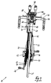
- Fig. 3 also shows the asymmetrical arrangement of connecting rod 60 and front drive wheel 64, corresponding to the Sprockets 22 of the bottom bracket 20.
- FIG. 4 an enlargement of the area of the link 34 of Fig. 1 is one Route 82 shown to overcome the upper and lower dead point.
- a dead point is reached when the connecting rod 60 and the lever 70 for power transmission from actuating lever 44 to the front drive wheel 64 lie in a straight line.
- a cylinder 84 of the path 82 there is a piston 86 guided with piston rod 88 in the axial direction.
- Feathers are arranged on the front, which depending on the position of the piston a tensile and / or compressive force can exercise.
- the springs 90, 92 can be replaced by equivalent means be, for example an elastic mass or a compressible gas.
- the path 82 can be pivoted at one end via a suspension bracket 96 the screw-clamp connection 45 for the actuating lever 44.
- the piston rod 88 is also pivotable with a bracket 98 a clamp 94 held on the connecting rod 60.
- This connecting rod 60 for the front drive wheel 64 is in Fig. 4 in the optimal pull position for the operating lever 44 shown.
- the spring 90 pushes and / or pulls the spring 92 Connecting rod 60 leading beyond the dead point.
- a housing in the area of the screw-clamp connection 45 a housing can be formed. Through double storage and a path installed in the housing can the dead point from the front be moved backwards.
- FIG. 4 the screw-clamp connection 45 for the actuating lever 44 shown in detail.
- This or its screw-clamp connection 45 can be pivoted about an axis 104 by two coaxial bolts 112 (FIG. 7), which in turn is clamped to the fork tube 30 via a bearing 106 (FIG. 7) are..
- FIG. 5 are essential parts of the present invention without the already shown in Fig. 4 routing, mounted in the front of the bicycle and shown exploded.
- Fig. 6 shows an operating lever 44, essentially two double angled, parallel pipes with handles 48 on the free End up.
- the elbow supports 50 are on the screw-clamp connections 45 attached to the operating lever 44 so that they the pivoting movements of the Handlebar 34 or the operating lever 44 can follow.
- FIG. 7 shows a bearing 106 for the actuating lever 44 (FIGS. 1 to 4).
- the bearing 106 has a bore 108 for the fork tube 30 (FIG. 1) and one Screw 110 to fix on it.
- Two coaxial bolts 112 form the Pivot axis 104 of the actuating lever 44 (Fig. 4).
- Fig. 8 the star-shaped holder 66 for the ring gear 68 (Fig. 4) of the front drive wheel 64 shown.
- the rigid with this star-shaped holder 66 connected lever 70 has three bores 100 for a pin 114, which forms the lower flying pivot axis 71 (Fig. 4).
- Fig. 9 shows a fender 80 for the front drive wheel 64. It has several longitudinal slots 116 and a canopy 118.
- FIG. 10 shows the front wheel fork 32 with the fork tube 30.
- the upper area of the fork is the bearing 63 for the front drive wheel 64 supported.
Landscapes
- Engineering & Computer Science (AREA)
- Chemical & Material Sciences (AREA)
- Combustion & Propulsion (AREA)
- Transportation (AREA)
- Mechanical Engineering (AREA)
- Automatic Cycles, And Cycles In General (AREA)
- Steering Devices For Bicycles And Motorcycles (AREA)
- Axle Suspensions And Sidecars For Cycles (AREA)
Abstract
Description
- am Gabelrohr und/oder am Lenker des Fahrrades ein etwa horizontal nach vorn gerichteter Betätigungshebel mit horizontal verlaufender Schwenkachse montiert ist, wobei die Länge des das Vorderrad steuernden Betätigungshebels mit zwei Handgriffen individuell einstellbar ist,
- am Betätigungshebel über eine obere fliegende Schwenkachse, im Abstand a vom freien Hebelende, eine Pleuelstange angelenkt ist, welche mit einem an der Vorderradgabel gehalterten vorderen Antriebsrad verbunden ist, und
- dieses vordere Antriebsrad über ein endloses flexibles Antriebsorgan drehmomentfest mit einer Freilaufnabe des Vorderrades verbunden ist.
- Der Betätigungshebel ist längenverstellbar am Gabelrohr und/oder am Lenker befestigbar.
- Die Pleuelstange ist in variablem Abstand a vom freien Ende des Betätigungshebels befestigbar, zweckmässig ist der Abstand a 10 bis 20 cm, insbesondere etwa 15 cm.
- Die Pleuelstange ist in radialer Richtung einstellbar weit von der Achse des vorderen Antriebsrades entfernt befestigbar.
- Fig. 1 eine teilweise Seitenansicht eines Fahrrades,
- Fig. 2 eine teilweise perspektivische Ansicht eines Fahrrades,
- Fig. 3 eine Stirnansicht eines Fahrrades,
- Fig. 4 einen Ausschnitt aus Fig. 1 mit Wegführung,
- Fig. 5 eine Teilansicht der wesentlichen Teile des Fahrrads,
- Fig. 6 eine perspektivische Ansicht eines Betätigungshebels,
- Fig. 7 eine perspektivische Ansicht eines Lagers für den Betätigungshebel,
- Fig. 8 eine perspektivische Ansicht eines sternförmigen Trägers eines vorderen Antriebsrades,
- Fig. 9 eine perspektivische Ansicht eines Schutzblechs, und
- Fig. 10 eine perspektivische Ansicht einer Fahrradgabel mit einem Lager für das vordere Antriebsrad.
- einen dreieckförmigen Fahrradrahmen 12
- ein in wenigstens einer nicht dargestellten oder nur angedeuteten Gabel fest montiertes Hinterrad 14 mit mehreren Zahnkränzen 16,
- ein Sattel 18,
- ein Tretlager 20 mit drei Zahnkränzen 22, Tretkurbel 24 und Pedalen 26,
- ein in einem Steigrohr 28 des Fahrradrahmens 12 schwenkbar geführtes Gabelrohr 30 mit einer Vorderradgabel 32,
- einen sportlichen Lenker 34 mit zwei Handgriffen 36 und einem in der Vorderradgabel 32 eingesetzten Vorderrad 38 mit einer Freilaufnabe 40.
Claims (10)
- Fahrrad (10) mit einem Fussantrieb des Hinterrades (14) und einem an der schwenkbaren Vorderradgabel (32) und dem Gabelrohr (30) befestigten zusätzlichen Handantrieb des Vorderrades (38)
dadurch gekennzeichnet, dassam Gabelrohr (30) und/oder am Lenker (34) des Fahrrades (10) ein etwa horizontal nach vorn gerichteter Betätigungshebel (44) mit horizontal verlaufender Schwenkachse (104) montiert ist, wobei die Länge des das Vorderrad (38) steuernden Betätigungshebels (44) mit zwei Handgriffen (48) individuell einstellbar ist,am Betätigungshebel (44) über eine obere fliegende Schwenkachse (58), im Abstand (a) vom freien Hebelende, eine Pleuelstange (60) angelenkt ist, welche mit einem an der Vorderradgabel (32) gehalterten vorderen Antriebsrad (64) verbunden ist, unddieses vordere Antriebsrad (64) über ein endloses flexibles Antriebsorgan drehmomentfest mit einer Freilaufnabe (40) des Vorderrades (38) verbunden ist. - Fahrrad (10) nach Anspruch 1, dadurch gekennzeichnet, dass eine Wegführung (82) im unteren und oberen toten Punkt des vorderen Antriebsrades (64) ein Drehmoment ausübt.
- Fahrrad (10) nach Anspruch 2, dadurch gekennzeichnet, dass die Wegführung (82) ein an der Pleuelstange (60) und an der Vorderradgabel (32) oder am Gabelrohr (30) schwenkbar gehalterter Zylinder (84) mit zwei beidseits des Kolbens (86) angeordneten komprimierbaren Mitteln, vorzugsweise Federn (90,92) ist.
- Fahrrad (10) nach Anspruch 3, dadurch gekennzeichnet, dass der Zylinder (84) über eine Schraub-Klemmverbindung (45) zusammen mit dem Betätigungshebel (44) mittels eines Lagers (106) am Gabelrohr (30), die Kolbenstange (88) über eine Schelle (94) an der Pleuelstange (60) schwenkbar gehaltert sind.
- Fahrrad (10) nach einem der Ansprüche 1 bis 4, dadurch gekennzeichnet, dass der Betätigungshebel (44) im wesentlichen aus zwei parallel verlaufenden Rohren, mit nahe nebeneinander liegenden Handgriffen (48) am freien Ende, ausgebildet ist.
- Fahrrad (10) nach einem der Ansprüche 1 bis 5, dadurch gekennzeichnet, dass die obere fliegende Schwenkachse (58) der Pleuelstange (60) in Längsrichtung des Betätigungshebels (44) verstellbar ist, vorzugsweise in einem Abstand (a) von 10 bis 20 cm, insbesondere etwa 15 cm, vom freien Ende.
- Fahrrad (10) nach einem der Ansprüche 1 bis 6, dadurch gekennzeichnet, dass das vordere Antriebsrad (64) einen sternförmig angeordnetem Halter (66), wenigstens einen peripheren Zahnkranz (68) und einen in radialer Richtung in variablem Abstand einsetzbaren Bolzen (114) für die untere fliegende Schwenkachse (71) der Pleuelstange (60) umfasst.
- Fahrrad (10) nach einem der Ansprüche 1 bis 7, dadurch gekennzeichnet, dass der äussere Umfang des Antriebsrads (64), insbesondere die Zahnkränze (68), rund oder elliptisch mit auf der Verbindungsebene der Achse (102) des vorderen Antriebsrades (64) und der unteren fliegenden Schwenkachse (71) liegendem langem Durchmesser ausgebildet ist.
- Fahrrad (10) nach einem der Ansprüche 1 bis 8, dadurch gekennzeichnet, dass die Freilaufnabe (40) des Vorderrades (38) mit wenigstens einem Zahnkranz (74) verbunden ist, und das als Kette (72) ausgebildete endlose Transportorgan einen zugleich als Kettenspanner (76) ausgebildeter Übersetzungswechsler (52) aufweist.
- Fahrrad (10) nach einem der Ansprüche 1 bis 9, dadurch gekennzeichnet, dass das vordere Antriebsrad (64) ein Schutzblech (80) mit Kettenüberdachung (118) aufweist.
Applications Claiming Priority (2)
| Application Number | Priority Date | Filing Date | Title |
|---|---|---|---|
| CH20102000 | 2000-10-10 | ||
| CH20102000 | 2000-10-10 |
Publications (3)
| Publication Number | Publication Date |
|---|---|
| EP1197428A2 true EP1197428A2 (de) | 2002-04-17 |
| EP1197428A3 EP1197428A3 (de) | 2004-12-29 |
| EP1197428B1 EP1197428B1 (de) | 2006-06-21 |
Family
ID=4567112
Family Applications (1)
| Application Number | Title | Priority Date | Filing Date |
|---|---|---|---|
| EP01810990A Expired - Lifetime EP1197428B1 (de) | 2000-10-10 | 2001-10-10 | Fahrrad mit zusätzlichem Vorderradantrieb |
Country Status (3)
| Country | Link |
|---|---|
| EP (1) | EP1197428B1 (de) |
| AT (1) | ATE330838T1 (de) |
| DE (1) | DE50110222D1 (de) |
Cited By (2)
| Publication number | Priority date | Publication date | Assignee | Title |
|---|---|---|---|---|
| EP1580112A1 (de) * | 2004-03-25 | 2005-09-28 | Andreas Dipl.-Ing. Quellmalz | Fahrrad mit einem Lenker und einer zusätzlichen armkraftbetätigten Antriebsvorrichtung |
| WO2009072140A1 (en) * | 2007-12-03 | 2009-06-11 | Shruti Mishra | A bicycle, propelled manually, with facilities for both rear and front wheel propulsion |
Citations (2)
| Publication number | Priority date | Publication date | Assignee | Title |
|---|---|---|---|---|
| DE3132019A1 (de) | 1981-08-13 | 1983-03-03 | Werner 8901 Neusäss Sterzik | Fahrrad mit fuss- und handantrieb mit schwenkbarem lenker am drehbaren vorderrad-gabelrohr |
| US5282640A (en) | 1989-11-15 | 1994-02-01 | Ben Lindsey | Exercise bicycle |
Family Cites Families (9)
| Publication number | Priority date | Publication date | Assignee | Title |
|---|---|---|---|---|
| BE417158A (de) * | ||||
| CH98468A (fr) * | 1921-04-07 | 1923-04-02 | Taberlet Raymond | Bicyclette avec guidon moteur. |
| CH173599A (de) * | 1934-01-19 | 1934-11-30 | Pletscher Fritz | Fahrrad. |
| US3701543A (en) * | 1970-09-21 | 1972-10-31 | Wallace Clark | Drive mechanism for wheeled vehicle |
| DE2719846A1 (de) * | 1977-05-04 | 1978-11-09 | Walter Schulz | Fahrrad, insbesondere fuer trimmzwecke |
| US4147370A (en) * | 1977-12-29 | 1979-04-03 | Lindsey Jr Ben | Front wheel drive for a bicycle |
| DE2913912A1 (de) * | 1979-04-06 | 1980-10-23 | Gottfried Ehrentraut | Fahrrad mit zusaetzlichem vorderradantrieb |
| DE3234619A1 (de) * | 1982-09-18 | 1984-03-22 | Veit Dipl.-Ing. 6945 Hirschberg Lehmann | Federanordnungen zur totpunktueberwindung von antrieben fuer fahrraeder |
| DE4132794A1 (de) * | 1991-10-02 | 1993-04-08 | Guenter Scheuermann | Vorderradantrieb fuer fahrrad |
-
2001
- 2001-10-10 DE DE50110222T patent/DE50110222D1/de not_active Expired - Fee Related
- 2001-10-10 EP EP01810990A patent/EP1197428B1/de not_active Expired - Lifetime
- 2001-10-10 AT AT01810990T patent/ATE330838T1/de not_active IP Right Cessation
Patent Citations (2)
| Publication number | Priority date | Publication date | Assignee | Title |
|---|---|---|---|---|
| DE3132019A1 (de) | 1981-08-13 | 1983-03-03 | Werner 8901 Neusäss Sterzik | Fahrrad mit fuss- und handantrieb mit schwenkbarem lenker am drehbaren vorderrad-gabelrohr |
| US5282640A (en) | 1989-11-15 | 1994-02-01 | Ben Lindsey | Exercise bicycle |
Cited By (2)
| Publication number | Priority date | Publication date | Assignee | Title |
|---|---|---|---|---|
| EP1580112A1 (de) * | 2004-03-25 | 2005-09-28 | Andreas Dipl.-Ing. Quellmalz | Fahrrad mit einem Lenker und einer zusätzlichen armkraftbetätigten Antriebsvorrichtung |
| WO2009072140A1 (en) * | 2007-12-03 | 2009-06-11 | Shruti Mishra | A bicycle, propelled manually, with facilities for both rear and front wheel propulsion |
Also Published As
| Publication number | Publication date |
|---|---|
| ATE330838T1 (de) | 2006-07-15 |
| DE50110222D1 (de) | 2006-08-03 |
| EP1197428A3 (de) | 2004-12-29 |
| EP1197428B1 (de) | 2006-06-21 |
Similar Documents
| Publication | Publication Date | Title |
|---|---|---|
| DE3941768C1 (de) | ||
| DE3701803A1 (de) | Faltbares zweiraedriges fahrrad | |
| DE202012103125U1 (de) | Fitnessfahrrad für die Freizeit | |
| DE10082555B4 (de) | Fahrrad mit Hinterradschwinge | |
| DE19829750C2 (de) | Vorrichtung zur Bewegung des menschlichen Körpers | |
| DE102008054168B4 (de) | Fahrrad | |
| DE19931197A1 (de) | Fahrrad | |
| DE212005000038U1 (de) | Verbesserungen bei nutzergetriebenen, mit Rädern versehenen Fahrzeugen | |
| DE4342679A1 (de) | Tretkurbelantrieb mit einem Drehwinkel von 360 Grad sowie periodisch veränderlichen Hebelarmlängen für durch Muskelkraft angetriebene Fahrräder und Fahrzeuge | |
| EP1197428B1 (de) | Fahrrad mit zusätzlichem Vorderradantrieb | |
| DE102022000127B4 (de) | Effektives handbetriebenes zusätzliches Antriebssystem für muskelbetriebene Fahrzeuge | |
| DE202005013737U1 (de) | Fahrrad mit Vorderradantrieb durch Armmuskelkraft | |
| DE4329795C2 (de) | Fahrrad | |
| DE69507806T2 (de) | Kompaktes, ergonomisches fahrrad mit schwingenden pedalen | |
| DE19801461C2 (de) | Dreiradfahrzeug | |
| DE2913912A1 (de) | Fahrrad mit zusaetzlichem vorderradantrieb | |
| DE20216348U1 (de) | Trainingsfahrrad zum Antreiben mit Hilfe des Körpergewichtes | |
| DE10140040B4 (de) | Wellenantrieb mit einer Antriebsachse für Tretroller | |
| DE102004033810B4 (de) | Fahrradtandem | |
| DE3132019A1 (de) | Fahrrad mit fuss- und handantrieb mit schwenkbarem lenker am drehbaren vorderrad-gabelrohr | |
| DE2005822A1 (de) | Fahrzeug | |
| DE10331352A1 (de) | Mobiles Übungs- und Fortbewegungsgerät | |
| DE102009019138A1 (de) | Fahrrad mit Arm- und Beinantrieb | |
| EP1995165A2 (de) | Fahrrad mit Arm- und Beinantrieb | |
| DE10136957A1 (de) | Vorrichtungen für sekundenschnelle Sattelverstellung auf einem Großkreis um die Pedaltretlagerachse eines Fahrrads bei konstanter Sattelneigung |
Legal Events
| Date | Code | Title | Description |
|---|---|---|---|
| PUAI | Public reference made under article 153(3) epc to a published international application that has entered the european phase |
Free format text: ORIGINAL CODE: 0009012 |
|
| AK | Designated contracting states |
Kind code of ref document: A2 Designated state(s): AT BE CH CY DE DK ES FI FR GB GR IE IT LI LU MC NL PT SE TR |
|
| AX | Request for extension of the european patent |
Free format text: AL;LT;LV;MK;RO;SI |
|
| PUAL | Search report despatched |
Free format text: ORIGINAL CODE: 0009013 |
|
| AK | Designated contracting states |
Kind code of ref document: A3 Designated state(s): AT BE CH CY DE DK ES FI FR GB GR IE IT LI LU MC NL PT SE TR |
|
| AX | Request for extension of the european patent |
Extension state: AL LT LV MK RO SI |
|
| 17P | Request for examination filed |
Effective date: 20050624 |
|
| AKX | Designation fees paid |
Designated state(s): AT BE CH CY DE DK ES FI FR GB GR IE IT LI LU MC NL PT SE TR |
|
| GRAP | Despatch of communication of intention to grant a patent |
Free format text: ORIGINAL CODE: EPIDOSNIGR1 |
|
| GRAS | Grant fee paid |
Free format text: ORIGINAL CODE: EPIDOSNIGR3 |
|
| GRAA | (expected) grant |
Free format text: ORIGINAL CODE: 0009210 |
|
| AK | Designated contracting states |
Kind code of ref document: B1 Designated state(s): AT BE CH CY DE DK ES FI FR GB GR IE IT LI LU MC NL PT SE TR |
|
| PG25 | Lapsed in a contracting state [announced via postgrant information from national office to epo] |
Ref country code: IT Free format text: LAPSE BECAUSE OF FAILURE TO SUBMIT A TRANSLATION OF THE DESCRIPTION OR TO PAY THE FEE WITHIN THE PRESCRIBED TIME-LIMIT;WARNING: LAPSES OF ITALIAN PATENTS WITH EFFECTIVE DATE BEFORE 2007 MAY HAVE OCCURRED AT ANY TIME BEFORE 2007. THE CORRECT EFFECTIVE DATE MAY BE DIFFERENT FROM THE ONE RECORDED. Effective date: 20060621 Ref country code: FI Free format text: LAPSE BECAUSE OF FAILURE TO SUBMIT A TRANSLATION OF THE DESCRIPTION OR TO PAY THE FEE WITHIN THE PRESCRIBED TIME-LIMIT Effective date: 20060621 Ref country code: NL Free format text: LAPSE BECAUSE OF FAILURE TO SUBMIT A TRANSLATION OF THE DESCRIPTION OR TO PAY THE FEE WITHIN THE PRESCRIBED TIME-LIMIT Effective date: 20060621 Ref country code: IE Free format text: LAPSE BECAUSE OF FAILURE TO SUBMIT A TRANSLATION OF THE DESCRIPTION OR TO PAY THE FEE WITHIN THE PRESCRIBED TIME-LIMIT Effective date: 20060621 |
|
| REG | Reference to a national code |
Ref country code: GB Ref legal event code: FG4D Free format text: NOT ENGLISH |
|
| REG | Reference to a national code |
Ref country code: CH Ref legal event code: EP |
|
| REG | Reference to a national code |
Ref country code: IE Ref legal event code: FG4D Free format text: LANGUAGE OF EP DOCUMENT: GERMAN |
|
| REF | Corresponds to: |
Ref document number: 50110222 Country of ref document: DE Date of ref document: 20060803 Kind code of ref document: P |
|
| PG25 | Lapsed in a contracting state [announced via postgrant information from national office to epo] |
Ref country code: SE Free format text: LAPSE BECAUSE OF FAILURE TO SUBMIT A TRANSLATION OF THE DESCRIPTION OR TO PAY THE FEE WITHIN THE PRESCRIBED TIME-LIMIT Effective date: 20060921 Ref country code: DK Free format text: LAPSE BECAUSE OF FAILURE TO SUBMIT A TRANSLATION OF THE DESCRIPTION OR TO PAY THE FEE WITHIN THE PRESCRIBED TIME-LIMIT Effective date: 20060921 |
|
| PG25 | Lapsed in a contracting state [announced via postgrant information from national office to epo] |
Ref country code: ES Free format text: LAPSE BECAUSE OF FAILURE TO SUBMIT A TRANSLATION OF THE DESCRIPTION OR TO PAY THE FEE WITHIN THE PRESCRIBED TIME-LIMIT Effective date: 20061002 |
|
| GBT | Gb: translation of ep patent filed (gb section 77(6)(a)/1977) |
Effective date: 20060924 |
|
| PG25 | Lapsed in a contracting state [announced via postgrant information from national office to epo] |
Ref country code: MC Free format text: LAPSE BECAUSE OF NON-PAYMENT OF DUE FEES Effective date: 20061031 |
|
| PG25 | Lapsed in a contracting state [announced via postgrant information from national office to epo] |
Ref country code: PT Free format text: LAPSE BECAUSE OF FAILURE TO SUBMIT A TRANSLATION OF THE DESCRIPTION OR TO PAY THE FEE WITHIN THE PRESCRIBED TIME-LIMIT Effective date: 20061121 |
|
| NLV1 | Nl: lapsed or annulled due to failure to fulfill the requirements of art. 29p and 29m of the patents act | ||
| ET | Fr: translation filed | ||
| REG | Reference to a national code |
Ref country code: IE Ref legal event code: FD4D |
|
| PLBE | No opposition filed within time limit |
Free format text: ORIGINAL CODE: 0009261 |
|
| STAA | Information on the status of an ep patent application or granted ep patent |
Free format text: STATUS: NO OPPOSITION FILED WITHIN TIME LIMIT |
|
| 26N | No opposition filed |
Effective date: 20070322 |
|
| PGFP | Annual fee paid to national office [announced via postgrant information from national office to epo] |
Ref country code: CH Payment date: 20070914 Year of fee payment: 7 |
|
| BERE | Be: lapsed |
Owner name: WALDMEIER-KOLLER, RITA Effective date: 20061031 Owner name: WALDMEIER, ROBERT Effective date: 20061031 |
|
| PGFP | Annual fee paid to national office [announced via postgrant information from national office to epo] |
Ref country code: DE Payment date: 20071025 Year of fee payment: 7 |
|
| PG25 | Lapsed in a contracting state [announced via postgrant information from national office to epo] |
Ref country code: AT Free format text: LAPSE BECAUSE OF NON-PAYMENT OF DUE FEES Effective date: 20061010 |
|
| PG25 | Lapsed in a contracting state [announced via postgrant information from national office to epo] |
Ref country code: GR Free format text: LAPSE BECAUSE OF FAILURE TO SUBMIT A TRANSLATION OF THE DESCRIPTION OR TO PAY THE FEE WITHIN THE PRESCRIBED TIME-LIMIT Effective date: 20060922 |
|
| PGFP | Annual fee paid to national office [announced via postgrant information from national office to epo] |
Ref country code: FR Payment date: 20071016 Year of fee payment: 7 Ref country code: GB Payment date: 20071023 Year of fee payment: 7 |
|
| PG25 | Lapsed in a contracting state [announced via postgrant information from national office to epo] |
Ref country code: LU Free format text: LAPSE BECAUSE OF NON-PAYMENT OF DUE FEES Effective date: 20061010 Ref country code: TR Free format text: LAPSE BECAUSE OF FAILURE TO SUBMIT A TRANSLATION OF THE DESCRIPTION OR TO PAY THE FEE WITHIN THE PRESCRIBED TIME-LIMIT Effective date: 20060621 |
|
| PG25 | Lapsed in a contracting state [announced via postgrant information from national office to epo] |
Ref country code: CY Free format text: LAPSE BECAUSE OF FAILURE TO SUBMIT A TRANSLATION OF THE DESCRIPTION OR TO PAY THE FEE WITHIN THE PRESCRIBED TIME-LIMIT Effective date: 20060621 |
|
| REG | Reference to a national code |
Ref country code: CH Ref legal event code: PL |
|
| GBPC | Gb: european patent ceased through non-payment of renewal fee |
Effective date: 20081010 |
|
| REG | Reference to a national code |
Ref country code: FR Ref legal event code: ST Effective date: 20090630 |
|
| PG25 | Lapsed in a contracting state [announced via postgrant information from national office to epo] |
Ref country code: DE Free format text: LAPSE BECAUSE OF NON-PAYMENT OF DUE FEES Effective date: 20090501 Ref country code: BE Free format text: LAPSE BECAUSE OF FAILURE TO SUBMIT A TRANSLATION OF THE DESCRIPTION OR TO PAY THE FEE WITHIN THE PRESCRIBED TIME-LIMIT Effective date: 20061031 |
|
| PG25 | Lapsed in a contracting state [announced via postgrant information from national office to epo] |
Ref country code: CH Free format text: LAPSE BECAUSE OF NON-PAYMENT OF DUE FEES Effective date: 20081031 Ref country code: LI Free format text: LAPSE BECAUSE OF NON-PAYMENT OF DUE FEES Effective date: 20081031 Ref country code: FR Free format text: LAPSE BECAUSE OF NON-PAYMENT OF DUE FEES Effective date: 20081031 |
|
| PG25 | Lapsed in a contracting state [announced via postgrant information from national office to epo] |
Ref country code: GB Free format text: LAPSE BECAUSE OF NON-PAYMENT OF DUE FEES Effective date: 20081010 |