EP1197464A2 - Rohrförmiger Aufzugsschacht - Google Patents
Rohrförmiger Aufzugsschacht Download PDFInfo
- Publication number
- EP1197464A2 EP1197464A2 EP01124201A EP01124201A EP1197464A2 EP 1197464 A2 EP1197464 A2 EP 1197464A2 EP 01124201 A EP01124201 A EP 01124201A EP 01124201 A EP01124201 A EP 01124201A EP 1197464 A2 EP1197464 A2 EP 1197464A2
- Authority
- EP
- European Patent Office
- Prior art keywords
- tubular body
- cabin
- car
- elevator system
- wall
- Prior art date
- Legal status (The legal status is an assumption and is not a legal conclusion. Google has not performed a legal analysis and makes no representation as to the accuracy of the status listed.)
- Granted
Links
- 230000007246 mechanism Effects 0.000 claims abstract description 22
- 230000033001 locomotion Effects 0.000 claims description 14
- 230000001360 synchronised effect Effects 0.000 claims description 9
- 238000009434 installation Methods 0.000 claims description 7
- 238000005259 measurement Methods 0.000 claims description 7
- 238000013461 design Methods 0.000 claims description 6
- 230000001105 regulatory effect Effects 0.000 claims description 3
- 238000005096 rolling process Methods 0.000 claims description 3
- 230000004913 activation Effects 0.000 claims description 2
- 230000008901 benefit Effects 0.000 abstract description 6
- 108010066114 cabin-2 Proteins 0.000 description 31
- 238000010276 construction Methods 0.000 description 11
- 238000011161 development Methods 0.000 description 8
- 230000006835 compression Effects 0.000 description 5
- 238000007906 compression Methods 0.000 description 5
- 239000000463 material Substances 0.000 description 4
- 238000012549 training Methods 0.000 description 3
- 230000007547 defect Effects 0.000 description 2
- 230000002349 favourable effect Effects 0.000 description 2
- 229910000831 Steel Inorganic materials 0.000 description 1
- 208000012886 Vertigo Diseases 0.000 description 1
- 230000000712 assembly Effects 0.000 description 1
- 238000000429 assembly Methods 0.000 description 1
- 230000005540 biological transmission Effects 0.000 description 1
- 230000015572 biosynthetic process Effects 0.000 description 1
- 230000008859 change Effects 0.000 description 1
- 230000036461 convulsion Effects 0.000 description 1
- 230000008878 coupling Effects 0.000 description 1
- 238000010168 coupling process Methods 0.000 description 1
- 238000005859 coupling reaction Methods 0.000 description 1
- 230000005284 excitation Effects 0.000 description 1
- 230000006872 improvement Effects 0.000 description 1
- 238000012423 maintenance Methods 0.000 description 1
- 230000007257 malfunction Effects 0.000 description 1
- 238000004519 manufacturing process Methods 0.000 description 1
- 239000002184 metal Substances 0.000 description 1
- 230000009467 reduction Effects 0.000 description 1
- 230000003068 static effect Effects 0.000 description 1
- 239000010959 steel Substances 0.000 description 1
- 230000003319 supportive effect Effects 0.000 description 1
- 238000004804 winding Methods 0.000 description 1
Images


Classifications
-
- B—PERFORMING OPERATIONS; TRANSPORTING
- B66—HOISTING; LIFTING; HAULING
- B66B—ELEVATORS; ESCALATORS OR MOVING WALKWAYS
- B66B11/00—Main component parts of lifts in, or associated with, buildings or other structures
- B66B11/0035—Arrangement of driving gear, e.g. location or support
- B66B11/004—Arrangement of driving gear, e.g. location or support in the machine room
-
- B—PERFORMING OPERATIONS; TRANSPORTING
- B66—HOISTING; LIFTING; HAULING
- B66B—ELEVATORS; ESCALATORS OR MOVING WALKWAYS
- B66B9/00—Kinds or types of lifts in, or associated with, buildings or other structures
- B66B9/04—Kinds or types of lifts in, or associated with, buildings or other structures actuated pneumatically or hydraulically
-
- E—FIXED CONSTRUCTIONS
- E04—BUILDING
- E04F—FINISHING WORK ON BUILDINGS, e.g. STAIRS, FLOORS
- E04F17/00—Vertical ducts; Channels, e.g. for drainage
- E04F17/005—Lift shafts
Definitions
- the invention relates to elevator systems for buildings with a car, which has a traction device is connected to a drive mechanism.
- Known elevator systems essentially consist on the one hand of an elevator shaft with guide rails, shaft doors, a cabin including safety gear and magnetic switch, a counterweight and information-providing devices and on the other hand a machine room of the machine as electric motors or hydraulic drives, a speed limiter, a control and a main switch. Solutions of this type are described, inter alia, in the publications EP 0 955 262 A1 (hydraulic elevator), EP 0 957 060 A1 (hydraulic rope elevator), DE 198 51 726 A1 (elevator with a spindle lifting rope drive), DE 199 02 853 A1 (passenger rope elevator), DE 298 14 744 U1 (elevator with drive) and DE 298 19 566 U1 (elevator).
- Elevator systems of this type are distinguished by a complicated and complex structure. The effort is very uneconomical, especially for buildings with a small number of floors. For example, there are additional high costs for the tenants, so that the rental costs increase significantly.
- the drives are connected to the cars.
- Such solutions are listed inter alia in EP 0 614 843 A1 (drive device for a self-propelled elevator car) and DE 198 34 994 A1 (elevator system with integrated machine unit). No counterweights and traction devices are used in these elevator systems. However, guide rails and cabin frames are also required. The effort for coupling the drives and the guide rails and thus for the transmission of motion between the drive and the cabin increases.
- EP 0 550 904 A1 pneumatic vacuum elevator system
- the cabin is moved in a shaft via a pneumatic pressure change.
- the technological structure of such an elevator can only be implemented in a very complex manner due to the airtight guides between the cabin and the shaft, which are particularly necessary.
- the effort increases with the loads to be transported. Accordingly, high pressure differences in the shaft are necessary for large loads.
- An air exchange must be ensured when the occupied cabin moves in the shaft. This is not the case with the pneumatic vacuum lift system described.
- the invention specified in claim 1 is based on the problem of a Easy to create elevator for building that continues to stand out distinguishes that this is both under construction and in existing buildings can be easily installed or attached.
- the tubular body in a self-supporting and supportive and / or load-bearing construction with a closed inner wall according to the Further development of claim 2 ensures a separate and independent of the building Design of the elevator system.
- the elevator system can easily both inside as well as placed outside of a building. Another advantage is there in that the elevator systems are also installed in existing buildings can without affecting the statics of this building.
- the tubular body is dimensioned so that it all results from the operation of the elevator absorbs horizontal and vertical forces.
- the tubular body is an assembly that is largely independent of other on-site trades. The realization of the tubular body in particular from several parts ensures easier installation, preferably in existing buildings.
- At least one opening between either the top of the cabin and the Inner wall of the tubular body or the cover plate of the cabin after the Further development of claim 3 ensures the air balance between the interior the cabin and the volume of the tubular body above it movement or when the cabin is stationary in the tubular body.
- the opening must be so large that there is always a sufficient one when the cabin is occupied Air exchange is guaranteed.
- Air exchange means compression and suction during the movements of the cabin.
- the element in particular a seal between the bottom plate of the cabin and the Inner wall of the tubular body according to the development of the claim 6 secures a compressible air cushion to brake the movement of the cabin in the event of an unwanted draining or tearing of the traction device.
- a seal between the bottom plate of the cabin and the Inner wall of the tubular body secures a compressible air cushion to brake the movement of the cabin in the event of an unwanted draining or tearing of the traction device.
- An electric synchronous motor or servo drive as a drive mechanism for the Cabin in the tubular body according to the development of claim 8 is characterized by freedom from maintenance and favorable heat development. Such Drive mechanisms can be controlled so that even at low speeds large transferable torques can be achieved. This is a direct drive for them Movement of the cabin is given in the tubular body. Conventionally necessary Counterweights including their structural necessities are not necessary.
- Sliding bodies and / or rolling elements on the one hand on the cabin and on the other hand between the cabin and the inner wall of the tubular body after the training of claim 9 improve the leadership of the cabin in the tubular body. Tilting movements of the cabin, especially when moving off, are largely avoided excluded, so that safe operation is given.
- the encoder and the device for position measurement after the training of Claim 11 is the automatic function of the elevator system according to the invention ge waterproofrleistbar.
- the controllable valve can also be connected to it be, so that the associated advantages are guaranteed.
- an elevator installation for buildings 15 essentially consists of a tubular body 1, a car 2, a drive mechanism 4, a traction mechanism 3 and a control system.
- 1 is a sectional side view of an elevator system in principle.
- the tubular body 1 is arranged in or on the building 15 vertically extending over all floors 16 (representations in FIGS. 4 and 5). It consists of one part or several parts that are assembled, assembled and connected during installation or attachment from above or below.
- the tubular body 1 has a closed inner wall. Furthermore, this is realized in a self-supporting and supporting and / or supporting construction. For this purpose, the tubular body 1 has a suitable ribbing and / or is provided with additional supporting construction elements.
- the ribs or the construction elements are arranged lengthways, diagonally and horizontally. Both variants ensure a low use of material with the same stiffness and strength of the tubular body 1.
- the tubular body 1 consists of a metal, in particular a steel, a plastic, in particular a laminate, or a glass-like material.
- the tubular body 1 has a closable opening as an access door 9.
- the tubular body 1 is closed in the lower region and a free space 6 is present between this closure 5 and the lowest opening 11.
- a cabin 2 for the vertical transport of at least two people and an ambulance.
- the cabin 2 is a self-supporting construction with a lockable cabin door 10, a base 7 and a cover plate 8.
- the cross sections of the tubular body 1 and at least the base plate 7 of the cabin 2 are of the same design, in particular square or circular.
- the cabin door 10 is designed such that it can be moved into the interior of the cabin 2 or between a double wall as a cabin wall.
- the constructions necessary for this are known.
- the drive mechanism 4 is located in the upper region of or on the tubular body / body 1.
- the drive mechanism is arranged on or in the vicinity of the tubular body / s 1, the traction means 3 being deflected via rollers in each case becomes.
- the drive mechanism 4 is an electric synchronous motor or electric servo drive. In the synchronous motor, the electrically generated excitation field rotates in the stator depending on the speed.
- Permanent magnets are in the rotor and three-phase windings for generating the rotating field are attached to the stator.
- a frequency converter is used to control the synchronous motor.
- the drive mechanism 4 is connected directly or via a gear to a traction device 3 and the traction device 3 to the cover plate 8 of the cabin 2.
- an unlinked, for example as a rope, or an articulated, for example as a chain, is used as the traction means 3.
- the cab 2 can be moved directly up or down, depending on the control, via the drive mechanism 4 and the traction means 3.
- the traction device 3 is wound on a shaft or runs from this.
- the tubular body 1 simultaneously represents the guidance of the cabin 2.
- the tubular Body 1 sliding body and / or rolling elements.
- balls can be used, which are held in at least one correspondingly shaped cage, which in turn is attached to the cabin 2.
- the tubular body 1 can be installed in or on a building 15 both as a separate device and as an additional self-contained elevator system.
- existing access doors 9 can also be used. However, it must be ensured that a lock is present between the openings of the tubular body 1 and the access doors 9 (illustration in FIG. 3).
- the openings of the tubular body 1 can be closed by means of sliding doors (illustration in FIG. 2). The sliding doors are guided on the tubular body 1.
- the free space 6 between the termination 5 of the tubular body 1 and the bottom opening 11 via a controllable valve be connected to the environment.
- the control of the valve is connected to a computer. This ensures that during a normal up and down movement, that there is no suction or compression in the interior of the tubular body 1 takes place.
- the valve is closed as quickly as possible, so that it is present under the cabin 2 Air volume can be compressed.
- Position securing elements are present. These are form-fitting or friction-locking elements, which releasably engage the inner wall of the tubular body 1 and on the Base plate 7 and / or the cover plate 8 of the cabin 2 are attached.
- the controls The actuators of the position securing elements are with the computer connected.
Landscapes
- Engineering & Computer Science (AREA)
- Structural Engineering (AREA)
- Architecture (AREA)
- Civil Engineering (AREA)
- Mechanical Engineering (AREA)
- Automation & Control Theory (AREA)
- Elevator Door Apparatuses (AREA)
- Types And Forms Of Lifts (AREA)
- Lift-Guide Devices, And Elevator Ropes And Cables (AREA)
- Flexible Shafts (AREA)
Abstract
Description
Bei weiteren Aufzuganlagen sind die Antriebe mit den Kabinen verbunden. Derartige Lösungen sind unter anderem in EP 0 614 843 A1 (Antriebsvorrichtung für eine selbstfahrende Aufzugskabine) und DE 198 34 994 A1 (Aufzuganlage mit integrierter Maschineneinheit) aufgeführt. Bei diesen Aufzuganlagen kommen keine Gegengewichte und Zugmittel zum Einsatz. Allerdings werden auch Führungsschienen und Kabinenrahmen benötigt. Der Aufwand für die Kopplung der Antriebe und der Führungsschienen und damit für die Bewegungsübertragung zwischen Antrieb und Kabine steigt. Insbesondere für Gebäude mit wenigen Etagen ergeben sich gleiche Nachteile wie bei den erst genannten Veröffentlichungen.
In der EP 0 550 904 A1 (Pneumatische Vakuumaufzuganlage) wird über eine pneumatische Druckänderung die Kabine in einem Schacht bewegt. Ein derartiger Aufzug ist in seinem technologischen Aufbau durch die insbesondere notwendigen luftdichten Führungen zwischen Kabine und Schacht nur sehr aufwendig realisierbar. Der Aufwand steigt dabei mit den zu transportierenden Lasten. Für große Lasten sind dementsprechend hohe Druckdifferenzen im Schacht notwendig. Bei einer Bewegung der besetzten Kabine im Schacht muss ein Luftaustausch gewährleistet sein. Dieser Sachverhalt ist mit der beschriebenen pneumatischen Vakuumaufzuganlage nicht gegeben.
Ein weiterer Vorteil derartig realisierter Aufzuganlagen besteht darin, dass diese leicht in entstehende oder bestehende Gebäude eingebaut werden können.
Grundlage dazu bildet der vertikal angeordnete rohrförmige Körper, indem die Kabine geführt ist und der rohrförmige Körper gleichzeitig die Führung darstellt. Dadurch ist eine sehr einfache Realisierung vorhanden, Führungsschienen sind nicht notwendig. Gleichzeitig ist es, leicht möglich, diesen rohrförmigen Körper in oder an entstehenden oder vorhandenen Gebäuden an- oder einzubauen. Der rohrförmige Körper kann auch aus mehreren Teilkörpern bestehen.
Dadurch dass
- der rohrförmige Körper durch verschließbare Öffnungen als Zugangstüren verschlossen ist,
- der rohrförmige Körper unten abgeschlossen ist,
- zwischen dem Abschluss des rohrförmigen Körpers und der untersten Öffnung ein freier Raum vorhanden ist und
- entweder die Bodenplatte der Kabine oder die Bodenplatte der Kabine mit einem diese umlaufenden Element, insbesondere eine Dichtung, den Querschnitt des rohrförmigen Körpers weitestgehend oder vollständig ausfüllen,
Durch diese Gestaltung der erfindungsgemäßen Aufzuganlagen sind die Kabinen als selbsttragende Konstruktionen ausführbar, so dass herkömmliche Kabinenrahmen entfallen und wesentliche Materialeinsparungen gegeben sind. Bei normaler Auf- und Abwärtsfahrt der Kabine können die Zugangstüren als verschließbare Öffnungen des rohrförmigen Körpers so ausgebildet sein, dass ein Luftausgleich möglich ist.
Die Kabine ist so ausgestaltet, dass mindestens zwei Personen und ein Krankenfahrstuhl platzierbar sind.
Ein weiterer Vorteil besteht darin, dass die strömenden Luftvolumina in dem rohrförmigen Körper zu einer rüttelfreien Bewegung genutzt werden können, so dass ein störungsfreies Bewegen der Kabine möglich ist.
Insgesamt sind damit sehr einfach zu realisierende Aufzuganlagen vorhanden, so dass durch den Einbau in entstehende oder bestehende Gebäude die ökonomischen Aufwendungen weitestgehend minimiert werden, so dass die dadurch nachfolgenden insbesondere finanziellen Belastungen für die Nutzer insbesondere als Mieter auf einem niedrigen Niveau gehalten werden können.
- wenigstens eine Nut in der Deckplatte und/oder der Bodenplatte der Kabine und in die Nut eingreifendes Konstruktionselement auf der Innenwandung oder
- mindestens eine Nut in der Innenwandung des rohrförmigen Körpers und in die Nut eingreifendes und darin bewegbares Konstruktionselement an der Boden- und/oder Deckplatte
Es zeigen:
- Fig.
- 1 eine prinzipielle Darstellung einer Aufzuganlage in einer Seitenansicht im Schnitt,
- Fig. 2
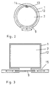
- eine prinzipielle Darstellung eines Querschnitts einer Aufzuganlage mit einer Antidrallführung,
- Fig. 3
- eine prinzipielle Darstellung eines Querschnitts einer Aufzuganlage mit bereits vorhandenen Zugangstüren,
- Fig. 4
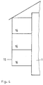
- eine prinzipielle Darstellung einer Aufzuganlage in einem Gebäude und
- Fig. 5
- eine prinzipielle Darstellung einer Aufzuganlage an einem Gebäude.
Der rohrförmige Körper 1 ist in oder an dem Gebäude 15 vertikal über alle Etagen 16 reichend angeordnet (Darstellungen in den Fig. 4 und 5). Dabei besteht dieser aus einem Teil oder mehreren Teilen, die bei dem Ein- oder Anbau von oben oder von unten zusammengesetzt, montiert und dabei verbunden werden. Der rohrförmige Körper 1 besitzt eine geschlossene Innenwandung. Weiterhin ist dieser in einer selbsttragenden und stützenden und/oder tragenden Bauweise realisiert. Dazu weist der rohrförmige Körper 1 eine geeignete Verrippung auf und/oder ist mit zusätzlichen stützenden Konstruktionselementen versehen. Die Rippen oder die Konstruktionselemente sind längs, diagonal und horizontal angeordnet. Beide Varianten sichern einen geringen Materialeinsatz bei gleichen Steifigkeiten und Festigkeiten des rohrförmigen Körpers 1. Dabei besteht der rohrförmige Körper 1 aus einem Metall, insbesondere einem Stahl, einem Kunststoff, insbesondere einem Laminat, oder einem glasartigen Stoff. Je Etage 16 besitzt der rohrförmige Körper 1 eine verschließbare Öffnung als Zugangstür 9. Der rohrförmige Körper 1 ist im unteren Bereich verschlossen und zwischen diesem Abschluss 5 und der untersten Öffnung 11 ist ein freier Raum 6 vorhanden.
Im rohrförmigen Körper 1 befindet sich bewegbar eine Kabine 2 zum vertikalen Transport wenigstens zweier Personen und eines Krankenfahrstuhles. Die Kabine 2 stellt eine selbsttragende Konstruktion mit einer verschließbaren Kabinentür 10, einer Boden- 7 und einer Deckplatte 8 dar. Die Querschnitte des rohrförmigen Körpers 1 und wenigstens der Bodenplatte 7 der Kabine 2 sind gleichgestaltet, insbesondere viereckig oder kreisförmig. Die Kabinentür 10 ist so ausgestaltet, dass diese in den Innenraum der Kabine 2 oder zwischen eine Doppelwandung als Kabinenwand verschoben werden kann. Die dafür notwendigen Konstruktionen sind bekannt.
In einer ersten Variante befindet sich im oberen Bereich des oder auf dem rohrförmigen Körpers/Körper 1 der Antriebsmechanismus 4. In einer zweiten Variante ist der Antriebsmechanismus an dem oder in Nähe des rohrförmigen Körper/s 1 angeordnet, wobei das Zugmittel 3 über Rollen jeweils umgelenkt wird. Der Antriebsmechanismus 4 ist ein elektrischer Synchronmotor oder elektrischer Servoantrieb. Beim Synchronmotor läuft das elektrisch erzeugte Erregerfeld im Ständer drehzahlabhängig um. Permanentmagneten sind im Läufer und Drehstromwicklungen zur Erzeugung des Rotationsfeldes sind auf dem Stator angebracht. Als Ansteuerung des Synchronmotors kommt ein Frequenzumrichter zum Einsatz.
Der Antriebsmechanismus 4 ist direkt oder über ein Getriebe mit einem Zugmittel 3 und das Zugmittel 3 mit der Deckplatte 8 der Kabine 2 verbunden. Als Zugmittel 3 kommt insbesondere ein Ungegliedertes z.B. als Seil oder ein Gegliedertes z.B. als Kette zum Einsatz. Über den Antriebsmechanismus 4 und das Zugmittel 3 kann die Kabine 2 je nach Ansteuerung direkt nach oben oder nach unten bewegt werden. Dabei wird das Zugmittel 3 auf einer Welle aufgewickelt oder läuft von dieser ab.
Der rohrförmige Körper 1 stellt gleichzeitig die Führung der Kabine 2 dar. Für eine Verbesserung der Führung in Form der Verringerung des Schwing- und Ruckverhaltens der Kabine 2 befinden sich zum Einen an der Kabine 2 und zum Anderen zwischen der Kabine 2 und der Innenwandung des rohrförmigen Körpers 1 Gleitkörper und/oder Wälzkörper. Im letzteren Fall können Kugeln zum Einsatz kommen, die in mindestens einen entsprechend ausgeformten Käfig gehalten werden, der wiederum an der Kabine 2 befestigt ist.
Der rohrförmige Körper 1 kann sowohl als separate Einrichtung als auch zusätzliche in sich geschlossene Aufzuganlage in oder an ein Gebäude 15 montiert werden. Im ersten Fall sind auch bereits vorhandene Zugangstüren 9 nutzbar. Dabei muss aber sichergestellt sein, dass eine Schleuse zwischen den Öffnungen des rohrförmigen Körpers 1 und den Zugangstüren 9 vorhanden ist (Darstellung in der Fig. 3). Im zweiten Fall sind die Öffnungen des rohrförmigen Körpers 1 mittels Schiebetüren verschließbar (Darstellung in der Fig. 2). Die Schiebetüren sind auf dem rohrförmigen Körper 1 geführt.
Die Deckplatte 8 der Kabine 2 ist so ausgebildet, dass ein Luftaustausch zwischen dem Innenraum der Kabine 2 und dem Innenraum des rohrförmigen Körpers 1 über der Kabine 2 gegeben ist. Dazu befindet sich zwischen der Deckplatte 8 der Kabine 2 und der Innenwandung des rohrförmigen Körpers 1 oder in der Deckplatte 8 der Kabine 2 wenigstens eine Öffnung. Im ersten
Fall ist der Querschnitt der Deckplatte 8 kleiner als der des rohrförmigen Körpers 1. Zwischen dem rohrförmigen Körper 1 und der Kabine 2 befindet sich insbesondere bei einem kreisförmigen Querschnitt weiterhin eine Antidrallführung. In einer ersten Ausführungsform ist in der Deckplatte 8 und/oder der Bodenplatte 7 der Kabine 2 wenigstens eine Nut 13 eingebracht und auf der Innenwandung mindestens ein vertikal angeordnetes und in die Nut 13 eingreifendes Konstruktionselement insbesondere in Form einer Schiene 14 angeordnet (Darstellung in der Fig. 2). In einer ersten Ausführungsform ist in die Innenwandung des rohrförmigen Körpers 1 eine vertikal verlaufende Nut eingebracht und an der Deckplatte 8 und/oder der Bodenplatte 9 der Kabine 2 befindet sich ein in die Nut eingreifendes und darin bewegbares Konstruktionselement insbesondere in Form eines Zapfens.
Zwischen dem rohrförmigen Körper 1 und der Kabine 2 sind die Bestandteile einer Einrichtung zur Positionsmessung angeordnet. Eine derartige Positionsmessung kann entweder über eine digitale oder eine analoge Messwerterfassung erfolgen.
Digitale Messwerterfassungssysteme sind unter anderem
- digital-inkrementale Messsysteme, wobei über die Unterteilung eines Weges in gleich große Teilstücke das Prinzip der Kettenmaßbildung zugrunde liegt,
- Durchlichtmesssysteme mit einer Lichtquelle, einem Maßstab, einer Abtastplatte und Fotoelementen oder
- digital-absolute Messsysteme, wobei jedem Streckenelement ein eindeutiger, auf
einem festen Nullpunkt bezogener Messwert zugeordnet ist.
Bei einem analogen Messwerterfassungssystem wird jedem Wert der Messgröße stetig ein Messsignal zugeordnet. Derartige Systeme arbeiten insbesondere induktiv als Resolver, Drehmelder, und Inductosyn. Ein weiteres ist das Laserinterferometer.
Für die Funktion der Aufzuganlage sind - mindestens eine Ansterung des Synchronmotors,
- ein mit dem Läufer des Synchronmotors verkoppelter Drehgeber,
- die jeweils an der Kabine 2 und dem rohrförmigen Körper 1 angeordneten Bestandteile einer Einrichtung zur Positionsmessung der Kabine 2 gegenüber dem rohrförmigen Körper 1 und
- Kontrollmechanismen für die offenen oder geschlossenen Positionen der Türen 9, 10 mit einer Steuer- und/oder Regeleinrichtung insbesondere einem Computer verbunden.
Claims (11)
- Aufzuganlage für Gebäude mit einer Kabine, die über ein Zugmittel mit einem Antriebsmechanismus verbunden ist, dadurch gekennzeichnet, dass die Kabine (2) in einem die Kabine (2) aufnehmenden, vertikal angeordneten und rohrförmigen Körper (1) mit mindestens einer mit einer Zugangstür (9) verschließbaren Öffnung je Etage (16) vertikal bewegbar angeordnet ist, dass der rohrförmige Körper (1) gleichzeitig die Führung der Kabine (2) ist, dass der rohrförmige Körper (1) unten abgeschlossen ist, dass zwischen dem Abschluss (5) des rohrförmigen Körpers (1) und der untersten Öffnung (11) ein freier Raum (6) vorhanden ist und dass zumindest entweder die Bodenplatte (7) der Kabine (2) oder die Bodenplatte (7) der Kabine (2) mit einer diese umlaufenden Dichtung (12) den Querschnitt des rohrförmigen Körpers (1) weitestgehend oder vollständig ausfüllen.
- Aufzuganlage nach Patentanspruch 1, dadurch gekennzeichnet, dass, der rohrförmige Körper (1) eine geschlossene Innenwandung besitzt, dass das ein selbsttragender und stützender und/oder tragender rohrförmiger Körper (1) ist und dass der rohrförmige Körper (1) aus einem Teil oder mehreren Teilen besteht.
- Aufzuganlage nach Patentanspruch 1, dadurch gekennzeichnet, dass sich zwischen der Deckplatte (8) der Kabine (2) und der Innenwandung des rohrförmigen Körpers (1) oder dass sich in der Deckplatte (8) der Kabine (2) wenigstens eine Öffnung befindet.
- Aufzuganlage nach Patentanspruch 1, dadurch gekennzeichnet, dass der Querschnitt des rohrförmigen Körpers (1) und der Bodenplatte (7) der Kabine (2) gleichgestaltet und entweder mehreckig sind oder die Form eines Kegelschnittes aufweisen.
- Aufzuganlage nach Patentanspruch 1, dadurch gekennzeichnet, dass in der Deckplatte (8) und/oder der Bodenplatte (7) der Kabine (2) mindestens eine Nut (13) eingebracht ist und dass sich auf der Innenwandung mindestens ein vertikal angeordnetes und in die Nut (13) eingreifendes Konstruktionselement insbesondere eine Führungsschiene (14) befindet oder dass in die Innenwandung des rohrförmigen Körpers (1) mindestens eine vertikal verlaufende Nut eingebracht und dass an der Deckplatte (8) und/oder der Bodenplatte (7) der Kabine (2) ein in die Nut eingreifendes und darin bewegbares Konstruktionselement insbesondere ein Zapfen angeordnet sind.
- Aufzuganlage nach Patentanspruch 1, dadurch gekennzeichnet, dass wenigstens zwischen der Bodenplatte (7) der Kabine (2) und der Innenwandung des rohrförmigen Körpers (1) eine den dazwischen liegenden Raum weitestgehend verschließende und auf der Innenwandung des rohrförmigen Körpers (1) gleitbares Element (12) so vorhanden ist, dass wenigstens während der Abwärtsbewegung der Kabine (2) im rohrförmigen Körper (1) der Verschluss weitestgehend gewährleistet ist.
- Aufzuganlage nach Patentanspruch 1, dadurch gekennzeichnet, dass der freie Raum (6) zwischen dem Abschluss (5) des rohrförmigen Körpers (1) und der untersten Öffnung (11) über ein steuerbares Ventil mit der Umwelt verbunden ist.
- Aufzuganlage nach Patentanspruch 1, dadurch gekennzeichnet, dass der Antriebsmechanismus (4) ein elektrischer Synchronmotor oder ein elektrischer Servoantrieb ist.
- Aufzuganlage nach Patentanspruch 1, dadurch gekennzeichnet, dass sich zum Einen an der Kabine (2) und zum Anderen zwischen der Kabine (2) und der Innenwandung des rohrförmigen Körpers (1) Gleitkörper und/oder Wälzkörper befinden.
- Aufzuganlage nach Patentanspruch 1, dadurch gekennzeichnet, dass die Kabine (2) wenigstens eine verschließbare Kabinentür (10) aufweist.
- Aufzuganlage nach den Patentansprüchen 1 bis 10, dadurch gekennzeichnet, dass mindestens eine Ansterung des Synchronmotors, ein mit dem Läufer des Synchronmotors verkoppelter Drehgeber und die jeweils an der Kabine (2) und dem rohrförmigen Körper (1) angeordneten Bestandteile einer Einrichtung zur Positionsmessung der Kabine (2) gegenüber dem rohrförmigen Körper (1) mit einer Steuer- und/oder Regeleinrichtung insbesondere einem Computer verbunden sind.
Applications Claiming Priority (4)
| Application Number | Priority Date | Filing Date | Title |
|---|---|---|---|
| DE20017605U | 2000-10-13 | ||
| DE2000150815 DE10050815C2 (de) | 2000-10-13 | 2000-10-13 | Aufzuganlage für Gebäude |
| DE10050815 | 2000-10-13 | ||
| DE20017605U DE20017605U1 (de) | 2000-10-13 | 2000-10-13 | Aufzuganlage für Gebäude |
Publications (3)
| Publication Number | Publication Date |
|---|---|
| EP1197464A2 true EP1197464A2 (de) | 2002-04-17 |
| EP1197464A3 EP1197464A3 (de) | 2002-08-21 |
| EP1197464B1 EP1197464B1 (de) | 2004-12-29 |
Family
ID=26007350
Family Applications (1)
| Application Number | Title | Priority Date | Filing Date |
|---|---|---|---|
| EP01124201A Expired - Lifetime EP1197464B1 (de) | 2000-10-13 | 2001-10-12 | Rohrförmiger Aufzugsschacht |
Country Status (3)
| Country | Link |
|---|---|
| EP (1) | EP1197464B1 (de) |
| AT (1) | ATE285976T1 (de) |
| DE (1) | DE50104947D1 (de) |
Cited By (3)
| Publication number | Priority date | Publication date | Assignee | Title |
|---|---|---|---|---|
| US20220009747A1 (en) * | 2020-07-09 | 2022-01-13 | Blissera Corp. | Hoistway mechanics of panoramic vacuum elevator |
| CN114014119A (zh) * | 2021-11-22 | 2022-02-08 | 黄淮学院 | 一种建筑井道安全防坠缓冲装置及其实施方法 |
| US12503341B2 (en) | 2020-07-09 | 2025-12-23 | Blissera Corp. | Cabin mechanics of panoramic vacuum elevator |
Family Cites Families (6)
| Publication number | Priority date | Publication date | Assignee | Title |
|---|---|---|---|---|
| US709494A (en) * | 1902-06-05 | 1902-09-23 | Amos W Leach | Safety device for elevators. |
| US761011A (en) * | 1904-02-23 | 1904-05-24 | John J Schwob | Elevator. |
| FR2598140B1 (fr) * | 1986-04-30 | 1988-10-07 | Affolter Jean Marie | Ascenseur pour le transport des personnes. |
| US4997060A (en) * | 1990-03-05 | 1991-03-05 | Sassak John J | Apparatus for controlling the descent of a passenger carrying body |
| CA2124253A1 (en) * | 1994-05-25 | 1995-11-26 | Mihail Ion Marcu | Free fall system |
| DE20017605U1 (de) * | 2000-10-13 | 2001-03-01 | Schmidt, Reinhard, Prof. Dr.-Ing.habil.Dr.h.c., 01723 Kesselsdorf | Aufzuganlage für Gebäude |
-
2001
- 2001-10-12 DE DE50104947T patent/DE50104947D1/de not_active Expired - Fee Related
- 2001-10-12 EP EP01124201A patent/EP1197464B1/de not_active Expired - Lifetime
- 2001-10-12 AT AT01124201T patent/ATE285976T1/de not_active IP Right Cessation
Cited By (5)
| Publication number | Priority date | Publication date | Assignee | Title |
|---|---|---|---|---|
| US20220009747A1 (en) * | 2020-07-09 | 2022-01-13 | Blissera Corp. | Hoistway mechanics of panoramic vacuum elevator |
| US12110208B2 (en) * | 2020-07-09 | 2024-10-08 | Blissera Corp. | Hoistway mechanics of panoramic vacuum elevator |
| US12503341B2 (en) | 2020-07-09 | 2025-12-23 | Blissera Corp. | Cabin mechanics of panoramic vacuum elevator |
| CN114014119A (zh) * | 2021-11-22 | 2022-02-08 | 黄淮学院 | 一种建筑井道安全防坠缓冲装置及其实施方法 |
| CN114014119B (zh) * | 2021-11-22 | 2022-05-27 | 黄淮学院 | 一种建筑井道安全防坠缓冲装置及其实施方法 |
Also Published As
| Publication number | Publication date |
|---|---|
| DE50104947D1 (de) | 2005-02-03 |
| ATE285976T1 (de) | 2005-01-15 |
| EP1197464A3 (de) | 2002-08-21 |
| EP1197464B1 (de) | 2004-12-29 |
Similar Documents
| Publication | Publication Date | Title |
|---|---|---|
| DE69431368T2 (de) | Antriebsscheibenaufzug | |
| DE69213201T2 (de) | Pneumatischer Vakuumaufzug | |
| EP1026116B1 (de) | Antriebseinheitszugang bei maschinenraumlosem Aufzug | |
| EP1246770B1 (de) | Inspektionsöffnung in einer aufzugskabine | |
| DE69519364T2 (de) | Treibscheibenaufzug und Maschinenraum für einen Treibscheibenaufzug | |
| DE69004382T2 (de) | Einstellung eines Treibers für einen Aufzug. | |
| WO2019034381A1 (de) | Aufzugsystem | |
| EP1489033A1 (de) | Aufzugsanlage mit in einem Schacht übereinander angeordneten Kabinen | |
| EP0885831A2 (de) | Aufzugsystem für vertikalen und horizontalen Transport | |
| EP1197464B1 (de) | Rohrförmiger Aufzugsschacht | |
| EP0979205B1 (de) | Seilgetriebener aufzug | |
| EP0926093B2 (de) | Aufzug, insbesondere Treibscheibenaufzug | |
| DE19712646C2 (de) | Seilaufzug | |
| DE10050815C2 (de) | Aufzuganlage für Gebäude | |
| DE20017605U1 (de) | Aufzuganlage für Gebäude | |
| DE3714053A1 (de) | Aufzug fuer personentransport | |
| DE19902853C2 (de) | Personen-Seilaufzug | |
| DE29717555U1 (de) | Aufzug | |
| DE2234904C3 (de) | Sicherheitsvorrichtung für Personen- und Lastenaufzüge | |
| DE69826819T2 (de) | Aufzug mit an Bord eingebauter Antriebseinrichtung | |
| WO2010072656A1 (de) | Mehrere aufzugskabinen in einem aufzugsschacht mit verbesserter schachtausnützung | |
| WO2007143871A2 (de) | Auszugsanlage und anordnung der antriebseinheit | |
| DE19752232A1 (de) | Seilaufzug | |
| EP0693453B1 (de) | Bauaufzug | |
| DE202004005413U1 (de) | Aufzug für Gebäude und Anlagen mit einer Kabine |
Legal Events
| Date | Code | Title | Description |
|---|---|---|---|
| PUAI | Public reference made under article 153(3) epc to a published international application that has entered the european phase |
Free format text: ORIGINAL CODE: 0009012 |
|
| AK | Designated contracting states |
Kind code of ref document: A2 Designated state(s): AT BE CH CY DE DK ES FI FR GB GR IE IT LI LU MC NL PT SE TR |
|
| AX | Request for extension of the european patent |
Free format text: AL;LT;LV;MK;RO;SI |
|
| PUAL | Search report despatched |
Free format text: ORIGINAL CODE: 0009013 |
|
| AK | Designated contracting states |
Kind code of ref document: A3 Designated state(s): AT BE CH CY DE DK ES FI FR GB GR IE IT LI LU MC NL PT SE TR |
|
| AX | Request for extension of the european patent |
Free format text: AL;LT;LV;MK;RO;SI |
|
| 17P | Request for examination filed |
Effective date: 20030213 |
|
| AKX | Designation fees paid |
Designated state(s): AT BE CH CY DE DK ES FI FR GB GR IE IT LI LU MC NL PT SE TR |
|
| 17Q | First examination report despatched |
Effective date: 20030716 |
|
| GRAP | Despatch of communication of intention to grant a patent |
Free format text: ORIGINAL CODE: EPIDOSNIGR1 |
|
| GRAS | Grant fee paid |
Free format text: ORIGINAL CODE: EPIDOSNIGR3 |
|
| GRAA | (expected) grant |
Free format text: ORIGINAL CODE: 0009210 |
|
| AK | Designated contracting states |
Kind code of ref document: B1 Designated state(s): AT BE CH CY DE DK ES FI FR GB GR IE IT LI LU MC NL PT SE TR |
|
| PG25 | Lapsed in a contracting state [announced via postgrant information from national office to epo] |
Ref country code: NL Free format text: LAPSE BECAUSE OF FAILURE TO SUBMIT A TRANSLATION OF THE DESCRIPTION OR TO PAY THE FEE WITHIN THE PRESCRIBED TIME-LIMIT Effective date: 20041229 Ref country code: GB Free format text: LAPSE BECAUSE OF FAILURE TO SUBMIT A TRANSLATION OF THE DESCRIPTION OR TO PAY THE FEE WITHIN THE PRESCRIBED TIME-LIMIT Effective date: 20041229 Ref country code: FR Free format text: LAPSE BECAUSE OF FAILURE TO SUBMIT A TRANSLATION OF THE DESCRIPTION OR TO PAY THE FEE WITHIN THE PRESCRIBED TIME-LIMIT Effective date: 20041229 Ref country code: TR Free format text: LAPSE BECAUSE OF FAILURE TO SUBMIT A TRANSLATION OF THE DESCRIPTION OR TO PAY THE FEE WITHIN THE PRESCRIBED TIME-LIMIT Effective date: 20041229 Ref country code: FI Free format text: LAPSE BECAUSE OF FAILURE TO SUBMIT A TRANSLATION OF THE DESCRIPTION OR TO PAY THE FEE WITHIN THE PRESCRIBED TIME-LIMIT Effective date: 20041229 Ref country code: IE Free format text: LAPSE BECAUSE OF FAILURE TO SUBMIT A TRANSLATION OF THE DESCRIPTION OR TO PAY THE FEE WITHIN THE PRESCRIBED TIME-LIMIT Effective date: 20041229 Ref country code: IT Free format text: LAPSE BECAUSE OF FAILURE TO SUBMIT A TRANSLATION OF THE DESCRIPTION OR TO PAY THE FEE WITHIN THE PRESCRIBED TIME-LIMIT;WARNING: LAPSES OF ITALIAN PATENTS WITH EFFECTIVE DATE BEFORE 2007 MAY HAVE OCCURRED AT ANY TIME BEFORE 2007. THE CORRECT EFFECTIVE DATE MAY BE DIFFERENT FROM THE ONE RECORDED. Effective date: 20041229 |
|
| REG | Reference to a national code |
Ref country code: GB Ref legal event code: FG4D Free format text: NOT ENGLISH |
|
| REG | Reference to a national code |
Ref country code: CH Ref legal event code: EP |
|
| REG | Reference to a national code |
Ref country code: IE Ref legal event code: FG4D Free format text: GERMAN |
|
| REF | Corresponds to: |
Ref document number: 50104947 Country of ref document: DE Date of ref document: 20050203 Kind code of ref document: P |
|
| PG25 | Lapsed in a contracting state [announced via postgrant information from national office to epo] |
Ref country code: SE Free format text: LAPSE BECAUSE OF FAILURE TO SUBMIT A TRANSLATION OF THE DESCRIPTION OR TO PAY THE FEE WITHIN THE PRESCRIBED TIME-LIMIT Effective date: 20050329 Ref country code: GR Free format text: LAPSE BECAUSE OF FAILURE TO SUBMIT A TRANSLATION OF THE DESCRIPTION OR TO PAY THE FEE WITHIN THE PRESCRIBED TIME-LIMIT Effective date: 20050329 Ref country code: DK Free format text: LAPSE BECAUSE OF FAILURE TO SUBMIT A TRANSLATION OF THE DESCRIPTION OR TO PAY THE FEE WITHIN THE PRESCRIBED TIME-LIMIT Effective date: 20050329 |
|
| PG25 | Lapsed in a contracting state [announced via postgrant information from national office to epo] |
Ref country code: ES Free format text: LAPSE BECAUSE OF FAILURE TO SUBMIT A TRANSLATION OF THE DESCRIPTION OR TO PAY THE FEE WITHIN THE PRESCRIBED TIME-LIMIT Effective date: 20050409 |
|
| NLV1 | Nl: lapsed or annulled due to failure to fulfill the requirements of art. 29p and 29m of the patents act | ||
| GBV | Gb: ep patent (uk) treated as always having been void in accordance with gb section 77(7)/1977 [no translation filed] |
Effective date: 20041229 |
|
| REG | Reference to a national code |
Ref country code: IE Ref legal event code: FD4D |
|
| PG25 | Lapsed in a contracting state [announced via postgrant information from national office to epo] |
Ref country code: AT Free format text: LAPSE BECAUSE OF NON-PAYMENT OF DUE FEES Effective date: 20051012 Ref country code: CY Free format text: LAPSE BECAUSE OF FAILURE TO SUBMIT A TRANSLATION OF THE DESCRIPTION OR TO PAY THE FEE WITHIN THE PRESCRIBED TIME-LIMIT Effective date: 20051012 |
|
| PG25 | Lapsed in a contracting state [announced via postgrant information from national office to epo] |
Ref country code: CH Free format text: LAPSE BECAUSE OF NON-PAYMENT OF DUE FEES Effective date: 20051031 Ref country code: LI Free format text: LAPSE BECAUSE OF NON-PAYMENT OF DUE FEES Effective date: 20051031 Ref country code: LU Free format text: LAPSE BECAUSE OF NON-PAYMENT OF DUE FEES Effective date: 20051031 Ref country code: BE Free format text: LAPSE BECAUSE OF NON-PAYMENT OF DUE FEES Effective date: 20051031 Ref country code: MC Free format text: LAPSE BECAUSE OF NON-PAYMENT OF DUE FEES Effective date: 20051031 |
|
| PLBE | No opposition filed within time limit |
Free format text: ORIGINAL CODE: 0009261 |
|
| STAA | Information on the status of an ep patent application or granted ep patent |
Free format text: STATUS: NO OPPOSITION FILED WITHIN TIME LIMIT |
|
| 26N | No opposition filed |
Effective date: 20050930 |
|
| EN | Fr: translation not filed | ||
| REG | Reference to a national code |
Ref country code: CH Ref legal event code: PL |
|
| BERE | Be: lapsed |
Owner name: *ZENTRUM DER FORDER- UND AUFZUGSTECHNIK ROSSWEIN G Effective date: 20051031 |
|
| PG25 | Lapsed in a contracting state [announced via postgrant information from national office to epo] |
Ref country code: PT Free format text: LAPSE BECAUSE OF NON-PAYMENT OF DUE FEES Effective date: 20050529 |
|
| PGFP | Annual fee paid to national office [announced via postgrant information from national office to epo] |
Ref country code: DE Payment date: 20071218 Year of fee payment: 7 |
|
| PG25 | Lapsed in a contracting state [announced via postgrant information from national office to epo] |
Ref country code: DE Free format text: LAPSE BECAUSE OF NON-PAYMENT OF DUE FEES Effective date: 20090501 |