EP1197771A1 - Verfahren zur erzeugung eines bragg-gitters in einem optischen wellenleiter - Google Patents
Verfahren zur erzeugung eines bragg-gitters in einem optischen wellenleiter Download PDFInfo
- Publication number
- EP1197771A1 EP1197771A1 EP01126367A EP01126367A EP1197771A1 EP 1197771 A1 EP1197771 A1 EP 1197771A1 EP 01126367 A EP01126367 A EP 01126367A EP 01126367 A EP01126367 A EP 01126367A EP 1197771 A1 EP1197771 A1 EP 1197771A1
- Authority
- EP
- European Patent Office
- Prior art keywords
- radiation
- mask
- period
- waveguide
- index
- Prior art date
- Legal status (The legal status is an assumption and is not a legal conclusion. Google has not performed a legal analysis and makes no representation as to the accuracy of the status listed.)
- Withdrawn
Links
- 230000003287 optical effect Effects 0.000 title claims abstract description 13
- 238000000034 method Methods 0.000 title claims description 16
- 230000005855 radiation Effects 0.000 claims abstract description 28
- 230000000737 periodic effect Effects 0.000 claims abstract description 12
- 239000000463 material Substances 0.000 claims abstract description 7
- 230000001747 exhibiting effect Effects 0.000 claims abstract description 3
- 239000013307 optical fiber Substances 0.000 claims description 7
- 230000005540 biological transmission Effects 0.000 abstract description 5
- 239000000835 fiber Substances 0.000 description 20
- VYPSYNLAJGMNEJ-UHFFFAOYSA-N Silicium dioxide Chemical compound O=[Si]=O VYPSYNLAJGMNEJ-UHFFFAOYSA-N 0.000 description 7
- YBMRDBCBODYGJE-UHFFFAOYSA-N germanium dioxide Chemical compound O=[Ge]=O YBMRDBCBODYGJE-UHFFFAOYSA-N 0.000 description 6
- 238000004519 manufacturing process Methods 0.000 description 6
- 230000003213 activating effect Effects 0.000 description 3
- 239000000377 silicon dioxide Substances 0.000 description 3
- 235000012239 silicon dioxide Nutrition 0.000 description 3
- 229940119177 germanium dioxide Drugs 0.000 description 2
- 238000005286 illumination Methods 0.000 description 2
- 230000004048 modification Effects 0.000 description 2
- 238000012986 modification Methods 0.000 description 2
- 206010034972 Photosensitivity reaction Diseases 0.000 description 1
- 238000010521 absorption reaction Methods 0.000 description 1
- XKRFYHLGVUSROY-UHFFFAOYSA-N argon Substances [Ar] XKRFYHLGVUSROY-UHFFFAOYSA-N 0.000 description 1
- 229910052786 argon Inorganic materials 0.000 description 1
- -1 argon ion Chemical class 0.000 description 1
- 230000001427 coherent effect Effects 0.000 description 1
- 239000005350 fused silica glass Substances 0.000 description 1
- 229910052732 germanium Inorganic materials 0.000 description 1
- GNPVGFCGXDBREM-UHFFFAOYSA-N germanium atom Chemical compound [Ge] GNPVGFCGXDBREM-UHFFFAOYSA-N 0.000 description 1
- 239000011521 glass Substances 0.000 description 1
- 230000002452 interceptive effect Effects 0.000 description 1
- 230000036211 photosensitivity Effects 0.000 description 1
- 230000001902 propagating effect Effects 0.000 description 1
- 239000011347 resin Substances 0.000 description 1
- 229920005989 resin Polymers 0.000 description 1
- 239000004065 semiconductor Substances 0.000 description 1
Images




Classifications
-
- G—PHYSICS
- G02—OPTICS
- G02B—OPTICAL ELEMENTS, SYSTEMS OR APPARATUS
- G02B6/00—Light guides; Structural details of arrangements comprising light guides and other optical elements, e.g. couplings
- G02B6/02—Optical fibres with cladding with or without a coating
-
- G—PHYSICS
- G02—OPTICS
- G02B—OPTICAL ELEMENTS, SYSTEMS OR APPARATUS
- G02B6/00—Light guides; Structural details of arrangements comprising light guides and other optical elements, e.g. couplings
- G02B6/10—Light guides; Structural details of arrangements comprising light guides and other optical elements, e.g. couplings of the optical waveguide type
- G02B6/12—Light guides; Structural details of arrangements comprising light guides and other optical elements, e.g. couplings of the optical waveguide type of the integrated circuit kind
- G02B6/122—Basic optical elements, e.g. light-guiding paths
- G02B6/124—Geodesic lenses or integrated gratings
-
- G—PHYSICS
- G02—OPTICS
- G02B—OPTICAL ELEMENTS, SYSTEMS OR APPARATUS
- G02B6/00—Light guides; Structural details of arrangements comprising light guides and other optical elements, e.g. couplings
- G02B6/02—Optical fibres with cladding with or without a coating
- G02B6/02057—Optical fibres with cladding with or without a coating comprising gratings
- G02B6/02076—Refractive index modulation gratings, e.g. Bragg gratings
- G02B6/02123—Refractive index modulation gratings, e.g. Bragg gratings characterised by the method of manufacture of the grating
- G02B6/02133—Refractive index modulation gratings, e.g. Bragg gratings characterised by the method of manufacture of the grating using beam interference
- G02B6/02138—Refractive index modulation gratings, e.g. Bragg gratings characterised by the method of manufacture of the grating using beam interference based on illuminating a phase mask
-
- G—PHYSICS
- G02—OPTICS
- G02B—OPTICAL ELEMENTS, SYSTEMS OR APPARATUS
- G02B6/00—Light guides; Structural details of arrangements comprising light guides and other optical elements, e.g. couplings
- G02B6/02—Optical fibres with cladding with or without a coating
- G02B6/02057—Optical fibres with cladding with or without a coating comprising gratings
- G02B6/02076—Refractive index modulation gratings, e.g. Bragg gratings
- G02B6/02123—Refractive index modulation gratings, e.g. Bragg gratings characterised by the method of manufacture of the grating
- G02B6/02142—Refractive index modulation gratings, e.g. Bragg gratings characterised by the method of manufacture of the grating based on illuminating or irradiating an amplitude mask, i.e. a mask having a repetitive intensity modulating pattern
-
- G—PHYSICS
- G02—OPTICS
- G02B—OPTICAL ELEMENTS, SYSTEMS OR APPARATUS
- G02B6/00—Light guides; Structural details of arrangements comprising light guides and other optical elements, e.g. couplings
- G02B6/10—Light guides; Structural details of arrangements comprising light guides and other optical elements, e.g. couplings of the optical waveguide type
- G02B6/12—Light guides; Structural details of arrangements comprising light guides and other optical elements, e.g. couplings of the optical waveguide type of the integrated circuit kind
-
- G—PHYSICS
- G02—OPTICS
- G02B—OPTICAL ELEMENTS, SYSTEMS OR APPARATUS
- G02B6/00—Light guides; Structural details of arrangements comprising light guides and other optical elements, e.g. couplings
- G02B6/02—Optical fibres with cladding with or without a coating
- G02B6/02057—Optical fibres with cladding with or without a coating comprising gratings
- G02B6/02076—Refractive index modulation gratings, e.g. Bragg gratings
- G02B6/0208—Refractive index modulation gratings, e.g. Bragg gratings characterised by their structure, wavelength response
- G02B6/021—Refractive index modulation gratings, e.g. Bragg gratings characterised by their structure, wavelength response characterised by the core or cladding or coating, e.g. materials, radial refractive index profiles, cladding shape
Definitions
- the present invention relates to methods for producing a Bragg grating in a core of an optical fiber or other light conducting path and, in particular, to methods for producing index of refraction changes which can provide a periodic variation along the length of a core of an optical fiber or other light conducting path which provides a Bragg reflection grating that is reflective to light in a preselected wavelength interval while being transparent to light at other wavelengths.
- a Bragg grating could be used in Wavelength Division Multiplexing (WDM) of several different wavelength bands on the same fiber for extending the utility of fiber optics for communications over several channels.
- WDM Wavelength Division Multiplexing
- the implementation of such a WDM system requires wavelength selective reflectors, multiplexers, demultiplexers and other components in which the index of refraction of the glass can be changed in a pre-determined way in the core of a fiber or other guided wave structure and in the vicinity of the light guiding path. It may also be desired to fabricate Bragg gratings for use as strain and temperature sensors.
- This method suffers from disadvantages in that it is difficult to obtain good quality gratings because: (a) of the precision required for the off-axis light illumination and (b) it is difficult to obtain equal light intensities in the transmitted zero order beam and the first order diffracted beam.
- Figure 1 shows an arrangement of a mask and radiation incident thereon to produce a diffraction pattern as used in the invention.
- Figure 2 shows a coordinate system that is convenient for describing the diffraction pattern.
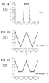
- Figures 3-9 show the intensity of radiation in the diffraction pattern.
- Figures 10-13 show the average intensity of the diffraction pattern averaged in the direction of propagation.
- Figure 14 shows an optical waveguide fiber with a Bragg grating made therein according to the invention.
- Figure 15 shows apparatus for making the Bragg grating of Fig 14.
- Figure 16 shows the mask and fiber holder of Fig 15 in detail and partly cut away.
- a diffraction pattern is formed in the region 104 by the light passing through the mask.
- a normalized coordinate system shown in Fig 2 is convenient for displaying the diffraction pattern within a representative repeat block 105.
- the coordinate a is parallel to the z-direction and increases from 0 to 1 as z increases by the repeat interval m.
- the coordinate b is parallel to the x-direction and increases from 0 to 1 as x increases by the repeat period px.
- Figs 3-9 show the relative intensity of the radiation in the diffraction pattern plotted against a for several values of b. Values shown in all of Figs 3-9 are for a transmitting fraction of mask equal to 0.25.
- the average depends on the value of a and the transmitting fraction of the mask.
- Figs 10-13 show such average intensities plotted against a for several values of the mask transmitting fraction. It may be seen that in all the illustrated instances (and it is true in general) that the average intensity is repeated in the period m so that in fact the average intensity is periodic in the z-direction with a period m/2.
- the wavefront impinging on the mask has been supposed to be planar and to continue directly into the space of the diffraction pattern.
- curved wavefronts and lenses and mirrors positioned along the path of the mask and the diffraction space can introduce scale magnification factor.
- the quantity m defining the scale of representative repeat block 105 should be interpreted as the repeat period of a projection of the mask (as projected by the radiation incident on the mask according to rules of geometric optics) onto the representative repeat block of interest.
- the magnification factor is one and the period of the mask is equal to the period of its projection.
- optical waveguide fiber 12 as shown in Fig 14, has core 13 running along axis 14 and providing an optical path through the fiber.
- Core 13 is made of material exhibiting change of index when exposed to radiation of an actuating frequency.
- An exemplary and advantageous material is vitreous silicon dioxide in which is dissolved a few mole percent of germanium dioxide. Such material experiences a change in index when exposed to radiation of frequency of 1222 terahz.
- Bragg grating 15 is formed in core 13 by periodic variation in index along core axis 14, according to the invention.
- Apparatus 20 as shown in Fig 15 is used to make a grating 15 according to the invention.
- Apparatus 20 includes base structure 21 to which is affixed radiation source 22, collimating lens 23, and mask and fiber holder 24.
- Radiation source 22 includes lamp 25 emitting radiation at the actuating frequency of 1222 terahz supported behind pinhole 26.
- Holder 24, as shown in more detail in Fig 16, includes transparent mask support 27 supporting mask 28 which has a periodically repeated variation in transmission in an extended direction perpendicular to the sheet as drawn in Fig 15.
- Holder 24 also has a channel 29 which holds fiber 12 in place against mask 28 with the fiber axis 14 running parallel to the extended dimension of the mask.
- the period of the variation of the mask transmission is 2 times the desired period in index variation in the Bragg grating.
- a fiber containing a waveguide core made of germanium doped silicon dioxide is introduced into channel 29 and held in position against mask 28.
- Lamp 25 is actuated and provides a source emanate from pinhole 26.
- Radiation from pinhole 26 passes through collimating lens 23 where it is formed into a beam with a planar wavefront, which passes through mask support 27 and impinges with uniform wave phase on mask 28.
- the radiation forms a diffraction pattern as described above.
- the core 13, which is positioned in the diffraction field is exposed to radiation periodically varying along axis 14, the period being one half that of the mask.
- the core develops a pattern of index variation along its length corresponding to the variation of radiation exposure.
- the exposure is terminated and the fiber removed from the apparatus to provide a Bragg grating.
- the period of the diffraction pattern in the direction of the light path depends on the mask period and any magnification introduced by optical elements but is independent of the wavelength of the activating radiation.
- the period of the grating can be made whatever one wishes without any constraint arising from the wavelength of the activating radiation.
- a finite bandwidth of the source or a motion of the fiber relative to the mask smears out the diffraction pattern in the x-direction but not in the z-direction.
Landscapes
- Physics & Mathematics (AREA)
- General Physics & Mathematics (AREA)
- Optics & Photonics (AREA)
- Engineering & Computer Science (AREA)
- Manufacturing & Machinery (AREA)
- Microelectronics & Electronic Packaging (AREA)
- Diffracting Gratings Or Hologram Optical Elements (AREA)
- Optical Integrated Circuits (AREA)
- Optical Fibers, Optical Fiber Cores, And Optical Fiber Bundles (AREA)
Applications Claiming Priority (3)
| Application Number | Priority Date | Filing Date | Title |
|---|---|---|---|
| US07/963,839 US5351321A (en) | 1992-10-20 | 1992-10-20 | Bragg grating made in optical waveguide |
| US963839 | 1992-10-20 | ||
| EP93923380A EP0694172B1 (de) | 1992-10-20 | 1993-10-13 | Methode zur erzeugung eines bragg-gitters in einem optischen wellenleiter |
Related Parent Applications (1)
| Application Number | Title | Priority Date | Filing Date |
|---|---|---|---|
| EP93923380A Division EP0694172B1 (de) | 1992-10-20 | 1993-10-13 | Methode zur erzeugung eines bragg-gitters in einem optischen wellenleiter |
Publications (1)
| Publication Number | Publication Date |
|---|---|
| EP1197771A1 true EP1197771A1 (de) | 2002-04-17 |
Family
ID=25507786
Family Applications (2)
| Application Number | Title | Priority Date | Filing Date |
|---|---|---|---|
| EP01126367A Withdrawn EP1197771A1 (de) | 1992-10-20 | 1993-10-13 | Verfahren zur erzeugung eines bragg-gitters in einem optischen wellenleiter |
| EP93923380A Expired - Lifetime EP0694172B1 (de) | 1992-10-20 | 1993-10-13 | Methode zur erzeugung eines bragg-gitters in einem optischen wellenleiter |
Family Applications After (1)
| Application Number | Title | Priority Date | Filing Date |
|---|---|---|---|
| EP93923380A Expired - Lifetime EP0694172B1 (de) | 1992-10-20 | 1993-10-13 | Methode zur erzeugung eines bragg-gitters in einem optischen wellenleiter |
Country Status (7)
| Country | Link |
|---|---|
| US (1) | US5351321A (de) |
| EP (2) | EP1197771A1 (de) |
| JP (1) | JP2001503529A (de) |
| KR (1) | KR100302122B1 (de) |
| CA (1) | CA2145542C (de) |
| DE (1) | DE69332247T2 (de) |
| WO (1) | WO1994009396A1 (de) |
Families Citing this family (45)
| Publication number | Priority date | Publication date | Assignee | Title |
|---|---|---|---|---|
| US5104209A (en) * | 1991-02-19 | 1992-04-14 | Her Majesty The Queen In Right Of Canada, As Represented By The Minister Of Communications | Method of creating an index grating in an optical fiber and a mode converter using the index grating |
| US5363239A (en) * | 1992-12-23 | 1994-11-08 | At&T Bell Laboratories | Method for forming spatially-varying distributed Bragg reflectors in optical media |
| GB2289771B (en) * | 1994-05-26 | 1997-07-30 | Northern Telecom Ltd | Forming Bragg gratings in photosensitive waveguides |
| PE41196A1 (es) | 1994-07-25 | 1996-12-17 | Pirelli Cavi Spa | Sistema de telecomunicacion amplificado para transmisiones en multiplex por division de longitud de onda, capaz de limitar las variaciones en la potencia de salida |
| US5615008A (en) * | 1994-12-21 | 1997-03-25 | Beckman Instruments, Inc. | Optical waveguide integrated spectrometer |
| AUPN089895A0 (en) * | 1995-02-03 | 1995-03-02 | University Of Sydney, The | Broadband grating |
| US5604829A (en) * | 1995-04-17 | 1997-02-18 | Hughes Aircraft Company | Optical waveguide with diffraction grating and method of forming the same |
| US5903690A (en) * | 1996-07-05 | 1999-05-11 | D-Star Technologies, Inc. | Method for changing the refraction index in germanium silicate glass |
| US5875272A (en) * | 1995-10-27 | 1999-02-23 | Arroyo Optics, Inc. | Wavelength selective optical devices |
| US5805751A (en) * | 1995-08-29 | 1998-09-08 | Arroyo Optics, Inc. | Wavelength selective optical couplers |
| US6236782B1 (en) | 1995-08-29 | 2001-05-22 | Arroyo Optics, Inc. | Grating assisted coupler devices |
| US5748312A (en) * | 1995-09-19 | 1998-05-05 | United States Of American As Represented By The Secretary Of The Navy | Sensing apparatus and method for detecting strain between fiber bragg grating sensors inscribed into an optical fiber |
| JP3497298B2 (ja) * | 1995-10-23 | 2004-02-16 | 株式会社フジクラ | 光ファイバフィルタ |
| IT1276122B1 (it) | 1995-11-14 | 1997-10-24 | Pirelli Cavi Spa | Metodo e dispositivo per recuperare in via ottica il sincronismo di un segnale ottico digitale |
| CA2163061C (en) * | 1995-11-16 | 2002-01-08 | Yves Painchaud | Method for spatially controlling the period and amplitude of bragg filters |
| US5903689A (en) * | 1995-11-16 | 1999-05-11 | Institut National D'optique | Method for spatially controlling the period and amplitude of BRAGG filters |
| US5668901A (en) * | 1996-02-14 | 1997-09-16 | Corning Incorporated | Low reflectivity fiber bragg grating with rectangular reflection function |
| US5863449A (en) * | 1996-03-29 | 1999-01-26 | The Whitaker Corporation | Method for forming optical interferometer |
| CA2207226C (en) * | 1996-06-10 | 2005-06-21 | Sumitomo Electric Industries, Ltd. | Optical fiber grating and method of manufacturing the same |
| IT1283373B1 (it) | 1996-07-31 | 1998-04-17 | Pirelli Cavi S P A Ora Pirelli | Sistema di telecomunicazione ottica multicanale bidirezionale |
| US5857043A (en) * | 1996-08-12 | 1999-01-05 | Corning Incorporated | Variable period amplitude grating mask and method for use |
| US6169830B1 (en) | 1996-08-26 | 2001-01-02 | Arroyo Optics, Inc. | Methods of fabricating grating assisted coupler devices |
| US5837169A (en) * | 1996-11-19 | 1998-11-17 | Northern Telecom Limited | Creation of bragg reflactive gratings in waveguides |
| KR100206176B1 (ko) | 1996-12-03 | 1999-07-01 | 윤종용 | 광감쇠기및그제조방법 |
| EP0996862A4 (de) * | 1996-12-30 | 2000-05-03 | Star Technologies Inc D | Nah-uv erzeugung von brechzahlgitter mit phasenmaske |
| US5745617A (en) * | 1996-12-30 | 1998-04-28 | D-Star Technologies, Llc | Near-ultra-violet formation of refractive-index grating using reflective phase mask |
| US5953471A (en) * | 1997-07-01 | 1999-09-14 | Lucent Technologies, Inc. | Optical communication system having short period reflective Bragg gratings |
| GB2329484A (en) | 1997-09-22 | 1999-03-24 | Northern Telecom Ltd | Writing Bragg reflection gratings in optical waveguides |
| US5997140A (en) * | 1997-12-29 | 1999-12-07 | Novartis Ag | Actively controllable multifocal lens |
| US6139147A (en) * | 1998-11-20 | 2000-10-31 | Novartis Ag | Actively controllable multifocal lens |
| US6139146A (en) * | 1997-12-29 | 2000-10-31 | Novartis Ag | Programmable corrective lenses |
| US6160660A (en) * | 1997-12-31 | 2000-12-12 | Pirelli Cavi E Sistemi S.P.A. | Bidirectional optical transmission system for dense interleaved wavelength division multiplexing |
| US6298184B1 (en) * | 1998-12-04 | 2001-10-02 | Cidra Corporation | Method and apparatus for forming a tube-encased bragg grating |
| US6146713A (en) | 1999-03-25 | 2000-11-14 | Acme Grating Ventures, Llc | Optical transmission systems and apparatuses including Bragg gratings and methods of making |
| EP1048626B1 (de) | 1999-04-26 | 2004-05-19 | Corning Incorporated | Stabilisierung einer Glaskeramik |
| US6278817B1 (en) | 1999-08-31 | 2001-08-21 | Corning, Incorporated | Asymmetric low dispersion bragg grating filter |
| US20020093701A1 (en) * | 2000-12-29 | 2002-07-18 | Xiaoxiao Zhang | Holographic multifocal lens |
| US6611645B2 (en) | 2001-01-18 | 2003-08-26 | Veridian Erim International | Signal analyzer using tapped optical fibers |
| US6744950B2 (en) * | 2001-01-18 | 2004-06-01 | Veridian Systems | Correlators and cross-correlators using tapped optical fibers |
| US6898350B2 (en) * | 2001-01-18 | 2005-05-24 | General Dynamics Advanced Information Systems, Inc. | Interferometric focusing technique for forming taps in fibers |
| CA2358659A1 (fr) | 2001-10-09 | 2003-04-09 | Yves Painchaud | Technique d'ecriture de reseaux de bragg par controle des franges |
| US6987909B1 (en) | 2001-11-30 | 2006-01-17 | Corvis Corporation | Optical systems and athermalized optical component apparatuses and methods for use therein |
| US7310463B2 (en) * | 2002-09-09 | 2007-12-18 | Kyocera Corporation | Optical structural body, its manufacturing method and optical element |
| US7257301B2 (en) * | 2005-03-31 | 2007-08-14 | Baker Hughes Incorporated | Optical fiber |
| US8537377B2 (en) | 2011-04-27 | 2013-09-17 | Raytheon Company | Absolute position encoder |
Citations (4)
| Publication number | Priority date | Publication date | Assignee | Title |
|---|---|---|---|---|
| EP0352975A2 (de) * | 1988-07-26 | 1990-01-31 | AT&T Corp. | Lithographie-Verfahren mit verdoppeltem Auflösungsvermögen |
| US4974930A (en) * | 1989-11-13 | 1990-12-04 | At&T Bell Laboratories | Mode scrambler with non-invasive fabrication in an optical fiber's cladding |
| WO1991012545A1 (fr) * | 1990-02-06 | 1991-08-22 | Bertin & Cie | Procede de realisation d'un reseau d'indice dans une fibre optique, et reseau de capteurs quasi-distribue forme dans cette fibre |
| US5066133A (en) * | 1990-10-18 | 1991-11-19 | United Technologies Corporation | Extended length embedded Bragg grating manufacturing method and arrangement |
Family Cites Families (5)
| Publication number | Priority date | Publication date | Assignee | Title |
|---|---|---|---|---|
| EP0191063B1 (de) * | 1984-08-13 | 1992-05-13 | United Technologies Corporation | Verfahren zum einlagern optischer gitter in faseroptik |
| US4874941A (en) * | 1988-05-11 | 1989-10-17 | Simmonds Precision Products, Inc. | Optical displacement sensor with a multi-period grating |
| US5048913A (en) * | 1989-12-26 | 1991-09-17 | United Technologies Corporation | Optical waveguide embedded transverse spatial mode discrimination filter |
| US5061032A (en) * | 1989-12-26 | 1991-10-29 | United Technologies Corporation | Optical waveguide embedded light redirecting and focusing bragg grating arrangement |
| US5104209A (en) * | 1991-02-19 | 1992-04-14 | Her Majesty The Queen In Right Of Canada, As Represented By The Minister Of Communications | Method of creating an index grating in an optical fiber and a mode converter using the index grating |
-
1992
- 1992-10-20 US US07/963,839 patent/US5351321A/en not_active Expired - Lifetime
-
1993
- 1993-10-13 JP JP51022194A patent/JP2001503529A/ja active Pending
- 1993-10-13 KR KR1019950701510A patent/KR100302122B1/ko not_active Expired - Lifetime
- 1993-10-13 CA CA002145542A patent/CA2145542C/en not_active Expired - Fee Related
- 1993-10-13 EP EP01126367A patent/EP1197771A1/de not_active Withdrawn
- 1993-10-13 WO PCT/US1993/009757 patent/WO1994009396A1/en not_active Ceased
- 1993-10-13 DE DE69332247T patent/DE69332247T2/de not_active Expired - Lifetime
- 1993-10-13 EP EP93923380A patent/EP0694172B1/de not_active Expired - Lifetime
Patent Citations (4)
| Publication number | Priority date | Publication date | Assignee | Title |
|---|---|---|---|---|
| EP0352975A2 (de) * | 1988-07-26 | 1990-01-31 | AT&T Corp. | Lithographie-Verfahren mit verdoppeltem Auflösungsvermögen |
| US4974930A (en) * | 1989-11-13 | 1990-12-04 | At&T Bell Laboratories | Mode scrambler with non-invasive fabrication in an optical fiber's cladding |
| WO1991012545A1 (fr) * | 1990-02-06 | 1991-08-22 | Bertin & Cie | Procede de realisation d'un reseau d'indice dans une fibre optique, et reseau de capteurs quasi-distribue forme dans cette fibre |
| US5066133A (en) * | 1990-10-18 | 1991-11-19 | United Technologies Corporation | Extended length embedded Bragg grating manufacturing method and arrangement |
Also Published As
| Publication number | Publication date |
|---|---|
| CA2145542C (en) | 2002-05-07 |
| KR100302122B1 (ko) | 2001-10-22 |
| WO1994009396A1 (en) | 1994-04-28 |
| EP0694172B1 (de) | 2002-08-28 |
| CA2145542F (en) | 1994-04-28 |
| CA2145542A1 (en) | 1994-04-28 |
| US5351321A (en) | 1994-09-27 |
| KR950704706A (ko) | 1995-11-20 |
| JP2001503529A (ja) | 2001-03-13 |
| DE69332247D1 (de) | 2002-10-02 |
| DE69332247T2 (de) | 2004-02-05 |
| EP0694172A1 (de) | 1996-01-31 |
Similar Documents
| Publication | Publication Date | Title |
|---|---|---|
| EP0694172B1 (de) | Methode zur erzeugung eines bragg-gitters in einem optischen wellenleiter | |
| US6067391A (en) | Multiply periodic refractive index modulated optical filters | |
| CA2111808C (en) | Method for forming a bragg grating in an optical medium | |
| US5818988A (en) | Method of forming a grating in an optical waveguide | |
| US5940568A (en) | Planar optical waveguide, planar optical waveguide with Bragg grating, and method of fabricating such a planar optical waveguide | |
| US6545808B1 (en) | Phase mask with spatially variable diffraction efficiency | |
| US5604829A (en) | Optical waveguide with diffraction grating and method of forming the same | |
| JPH09508713A (ja) | 光格子 | |
| JP3330858B2 (ja) | 連続的にチャープした位相マスクの製造方法 | |
| FR2697642A1 (fr) | Méthode de fabrication de réseaux de diffraction de Bragg. | |
| US6915044B2 (en) | Tunable talbot interferometers for fiber bragg grating writing | |
| KR100334799B1 (ko) | 광섬유격자 제작 장치 및 방법 | |
| US5953471A (en) | Optical communication system having short period reflective Bragg gratings | |
| US5708739A (en) | Method and apparatus for photobleaching patterns in irradiated optical waveguides | |
| CA2237963C (en) | A method of and a device for making bragg gratings in optical fibres or waveguides | |
| CA2372939A1 (en) | Bragg grating made in optical waveguide | |
| US5985523A (en) | Method for irradiating patterns in optical waveguides containing radiation sensitive constituents | |
| JPH11295541A (ja) | 導波路型回折格子の製造方法及び導波路型回折格子製造装置 | |
| JPH08101322A (ja) | 透過型ファイバグレーティングフィルタの製造方法及びその装置 | |
| US6873762B1 (en) | Fabrication of fiber optic grating apparatus and method | |
| JPH10153718A (ja) | プレーナ形光導波路、ブラッグ格子を有するプレーナ形光導波路、および該プレーナ形光導波路を製造する方法 | |
| KR100334822B1 (ko) | 평면 도파로열 격자를 구비한 파장분할 다중/역다중화기의 중심파장 조절 방법 | |
| JPH10160949A (ja) | 光導波路型回折格子の製造方法 | |
| Rothhardt et al. | Characterization of chirped phase masks for UV applications by writing and investigation of fiber Bragg gratings | |
| Chen | Photorefractive effects in optical fibers grating fabrication and characterization |
Legal Events
| Date | Code | Title | Description |
|---|---|---|---|
| PUAI | Public reference made under article 153(3) epc to a published international application that has entered the european phase |
Free format text: ORIGINAL CODE: 0009012 |
|
| AC | Divisional application: reference to earlier application |
Ref document number: 694172 Country of ref document: EP |
|
| AK | Designated contracting states |
Kind code of ref document: A1 Designated state(s): CH DE DK ES FR GB IT LI NL SE |
|
| 17P | Request for examination filed |
Effective date: 20020617 |
|
| AKX | Designation fees paid |
Free format text: CH DE DK ES FR GB IT LI NL SE |
|
| STAA | Information on the status of an ep patent application or granted ep patent |
Free format text: STATUS: THE APPLICATION IS DEEMED TO BE WITHDRAWN |
|
| 18D | Application deemed to be withdrawn |
Effective date: 20060711 |