EP1198023B1 - Schaltung zur Ankopplung und Impedanzanpassung zwischen GPS-Antenne und Empfänger durch eine Glasscheibe - Google Patents
Schaltung zur Ankopplung und Impedanzanpassung zwischen GPS-Antenne und Empfänger durch eine Glasscheibe Download PDFInfo
- Publication number
- EP1198023B1 EP1198023B1 EP01308703A EP01308703A EP1198023B1 EP 1198023 B1 EP1198023 B1 EP 1198023B1 EP 01308703 A EP01308703 A EP 01308703A EP 01308703 A EP01308703 A EP 01308703A EP 1198023 B1 EP1198023 B1 EP 1198023B1
- Authority
- EP
- European Patent Office
- Prior art keywords
- glass plate
- signal transmission
- coaxial cable
- pair
- gps
- Prior art date
- Legal status (The legal status is an assumption and is not a legal conclusion. Google has not performed a legal analysis and makes no representation as to the accuracy of the status listed.)
- Expired - Lifetime
Links
- 239000011521 glass Substances 0.000 title claims description 55
- 230000008878 coupling Effects 0.000 title description 2
- 238000010168 coupling process Methods 0.000 title description 2
- 238000005859 coupling reaction Methods 0.000 title description 2
- 230000008054 signal transmission Effects 0.000 claims description 58
- 239000004020 conductor Substances 0.000 claims description 28
- 239000000853 adhesive Substances 0.000 claims description 6
- 230000001070 adhesive effect Effects 0.000 claims description 4
- 230000002093 peripheral effect Effects 0.000 description 2
- 230000005540 biological transmission Effects 0.000 description 1
- 239000003990 capacitor Substances 0.000 description 1
- 238000010586 diagram Methods 0.000 description 1
- 238000000034 method Methods 0.000 description 1
- 230000010363 phase shift Effects 0.000 description 1
- 238000001228 spectrum Methods 0.000 description 1
Images
Classifications
-
- H—ELECTRICITY
- H01—ELECTRIC ELEMENTS
- H01Q—ANTENNAS, i.e. RADIO AERIALS
- H01Q1/00—Details of, or arrangements associated with, antennas
- H01Q1/12—Supports; Mounting means
- H01Q1/1271—Supports; Mounting means for mounting on windscreens
- H01Q1/1285—Supports; Mounting means for mounting on windscreens with capacitive feeding through the windscreen
-
- H—ELECTRICITY
- H01—ELECTRIC ELEMENTS
- H01Q—ANTENNAS, i.e. RADIO AERIALS
- H01Q1/00—Details of, or arrangements associated with, antennas
- H01Q1/27—Adaptation for use in or on movable bodies
- H01Q1/32—Adaptation for use in or on road or rail vehicles
Definitions
- This invention relates to a signal transmission circuit for carrying out signal transmission between an antenna unit such as a GPS (global positioning system) antenna and a receiver body.
- an antenna unit such as a GPS (global positioning system) antenna and a receiver body.
- a GPS receiver is an apparatus for detecting a current position of a mobile station for a user by receiving signals radiated to earth from a plurality of GPS (global positioning system) satellites which orbit the earth.
- GPS global positioning system
- the GPS global positioning system
- the GPS receiver receives signals from four GPS satellites, it is possible to carry out a three-dimensional positioning. And if the GPS receiver receives signals from three GPS satellites, it is possible to carry out a two-dimensional positioning.
- the GPS is a global positioning system comprising twenty-four artificial satellites launched by the Department of Defense in the United States, a control station on earth, and mobile stations for users.
- the global positioning system it is possible to calculate the position, the direction of motion and the speed of the mobile station by measuring distances between the mobile station and three or more GPS satellites on the basis of time intervals taken for arrival of the signals.
- the global positioning system was originally used for military purposes, presently it is widely applied to car navigation systems or the like.
- the mobile stations may be not only automobiles but also airplanes, ships, or the like.
- car navigation means providing driver information by displaying a position of a driver's car on a map of a car-mounted machine in real time, by displaying road traffic information, and by calculating the most suitable route to a driver's destination.
- a GPS signal which is generated by the GPS satellite and transmitted to the ground, has a very weak strength
- the GPS signal may be buried by or covered by noise or other terrestrial signals.
- a PSK (Phase-Shift Keying) signal which is spread-spectrum modulated by using a PN (pseudo-noise) code, is used as the GPS signal
- the GPS receiver comprises a LNA (low noise amplifier) circuit for removing noise from the GPS signal and for amplifying an extracted GPS signal.
- a GPS antenna (or an antenna unit) is mounted on an outer surface of a body of the car by using magnets or the like.
- the GPS antenna (or the antenna unit) is a planar-type antenna.
- the planar-type antenna may be mounted on a metallic roof panel of the car or the like by magnetically attracting the planar-type antenna to the metallic roof panel.
- the GPS antenna (or the antenna unit) comprises an antenna element and a circuit board on which accompanying circuit elements including the above-mentioned LNA circuit are mounted. Received by the GPS antenna (the antenna unit), a signal is transmitted to a GPS receiver body, installed or loaded in the car or the automobile, through a signal transmission circuit.
- a conventional signal transmission circuit comprises the coaxial cable.
- the conventional signal transmission circuit comprises the coaxial cable as described above
- the conventional signal transmission circuit is disadvantageous in that it is necessary to lead the coaxial cable from the GPS antenna (the antenna unit) to the GPS receiver body through a gap in the car or the automobile, and this consumes a great deal of time.
- a method comprising the step of carrying out the signal transmission by using only the above-mentioned coaxial cable as the signal transmission circuit through a glass plate of the car (for example, a front window, a rear window, or other glass panel) without passing through a gap in the car.
- a glass plate of the car for example, a front window, a rear window, or other glass panel
- the coaxial cable has a low characteristic impedance of about 50 ohms
- a ground area in the glass plate must be made wide (large).
- the ground area may be equal to, for example, fifteen centimetres square, four centimetres square, or the like.
- US Patent 5,278,572 discloses a capacitive antenna coupling circuit for passing a signal through glass, the circuit in a basic form including a meandering conductor that has one end connected to a counter electrode and has the other end connected to a peripheral conductor that surrounds the meandering conductor and counter electrode.
- the core wire and ground of a coaxial cable respectively connect to the meandering conductor and peripheral conductor to produce a LC circuit at the frequencies being transmitted through the glass.
- US Patent 5,612,652 (Multiplex) discloses circuitry external of a window and circuitry internal of the window for passing a balanced RF signal from the external side to the internal side of the window. Also disclosed is power circuitry on both sides of the window for supplying electrical power from the internal side of the window to the external side.
- the present inventors have made extensive studies and considered various ideas in order to achieve a structure which needs not to widen (enlarge) the area of the ground in the glass plate on carrying out signal transmission through the glass plate.
- an unbalanced line such as a coaxial cable has low characteristic impedance of about 50 ohms
- a balanced line has higher characteristic impedance of, for example, about 200 ohms than that of the coaxial cable, it is possible to narrow (reduce) an area of a ground in the glass plate in comparison with a case of the coaxial cable.
- the present inventors arrived at a conclusion that it is possible to reduce the area of the ground in the glass plate by carrying out signal transmission between the glass plate using the balanced line having the high characteristic impedance and by using a balun in order to match between the unbalanced line (the coaxial cable) and the balanced line and it is therefore possible to miniaturize the signal transmission circuit.
- a signal transmission circuit is for transmitting a signal received in an antenna unit to a receiver body through a glass plate.
- the antenna unit has an output terminal.
- the receiver body has an input terminal.
- the glass plate has first and second surfaces which are opposite to each other.
- the signal transmission circuit includes a first signal transmission part for transmitting a high-frequency signal from the output terminal of the antenna unit to the first surface of the glass plate, and a second signal transmission part for transmitting the high-frequency signal from the second surface of the glass plate to the input terminal of the receiver body.
- the first signal transmission part includes: a first coaxial cable having an end connected to the output terminal of the antenna unit; and, a first interface circuit comprising: a first electrode pair consisting of a pair of electrodes adhered to the first surface of the glass plate; a first balanced line having an end pair connected to the first electrode pair; and, a first balun, disposed between another end of the first coaxial cable and another end pair of the first balanced line, for impedance-converting from the first coaxial cable to the first balanced line.
- the second signal transmission part includes: a second coaxial cable having an end connected to the input terminal of the receiver body; and, a second interface circuit comprising: a second electrode pair consisting of a pair of electrodes adhered to the second surface of the glass plate; a second balanced line having an end pair connected to the second electrode pair; and, a second balun, disposed between another end pair of the second balanced line and another end of the second coaxial cable, for impedance-converting from the second balanced line to the second coaxial cable.
- the first coaxial cable includes a central conductor and an external conductor, the central conductor being connected to the first balun.
- the second coaxial cable includes a central conductor and an external conductor, the central conductor being connected to the second balun.
- the external conductors are not in electrical connection with the first and second interface circuits.
- the external conductors are in electrical connection with ground but are not in electrical connection with the first and second interface circuits.
- the pair of electrodes of the first electrode pair are adhered to the first surface of the glass plate by means of adhesive, a magnet, or double-sided tape.
- the pair of electrodes of the second electrode pair are adhered to the second surface of the glass plate by means of adhesive, a magnet, or double-sided tape.
- the above-mentioned signal transmission circuit may be used in a global positioning system (GPS) receiver for use in a car navigation system.
- the antenna unit includes a GPS antenna mounted on an outer surface of a body of a car.
- the receiver body includes a GPS receiver body installed in the car.
- the glass plate includes a window or other glass plate of the car.
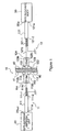
- the signal transmission circuit of Figure 1 relates to a GPS (global positioning system) receiver for use in a car navigation system.
- GPS global positioning system
- the GPS receiver comprises a GPS antenna 20 serving as an antenna unit mounted on an outer surface of a body of a car (not shown) (i.e. inside the car) and a GPS receiver body 30 installed in the car.
- the GPS antenna 20 and the GPS receiver body 30 are connected through a signal transmission circuit 10 according to the embodiment of this invention. That is, the signal transmission circuit 10 is a circuit for transmitting a signal received by the antenna unit (the GPS antenna) 20 to the GPS receiver body 30 through a glass plate 40.
- the antenna unit (the GPS antenna) 20 comprises an antenna element and a circuit board mounting circuit elements including a low-noise amplifier (LNA) circuit thereon.
- the GPS antenna (the antenna unit) 20 has an output terminal 20 out for outputting a signal received thereby to the exterior.
- the glass plate 40 may be a front glass plate of the car or a rear glass plate of the car.
- the GPS receiver body 30 has an input terminal 30 in for inputting a signal from the exterior.
- the signal transmission circuit 10 is the circuit for signal connecting between the output terminal 20 out of the GPS antenna (the antenna unit) 20 and the input terminal 30 in of the GPS receiver body 30 through the glass plate 40.
- the "signal connecting" means not to transmit a DC signal such as a power transmission but to transmittably connecting a high frequency signal.
- the feeding is carried out by a feeding circuit (not shown) which is different from the signal transmission circuit according to this invention. Inasmuch as such a feeding circuit is not directly related to this invention, description of the feeding circuit is omitted.
- the signal transmission circuit 10 is divided into a first signal transmission part 11 and a second signal transmission part 12.
- the glass plate 40 has a first or outer surface 41 and a second or inner surface 42 opposite to the first surface 41.
- the first signal transmission part 11 is for transmitting the high frequency signal from the output terminal 20 out of the GPS antenna (the antenna unit) 20 to the first surface 41 of the glass plate 40.
- the second signal transmission part 12 is for transmitting the high frequency signal from the second surface 42 of the glass plate 40 to the input terminal 30 in of the GPS receiver body 30.
- the glass plate 40 transmits the high frequency signal because the glass plate 40 serves as a capacitor.
- the first signal transmission part 11 comprises a first coaxial cable 111, a first electrode pair 112, a first balanced line 113, and a first balun 114.
- the first coaxial cable 111 has an end 111 a connected to the output terminal 20 out of the GPS antenna (the antenna unit) 20.
- the first electrode pair 112 consists of a pair of electrodes which are adhered to the first surface 41 of the glass plate 40. In addition, adhesion of the first electrode pair 112 to the first surface 41 of the glass plate 40 may be carried out, for example, by an adhesive agent, a magnet, double-sided tape, or the like.
- the first balanced line 113 has an end pair 113a connected to the first electrode pair 112.
- the first balun 114 is disposed between another end 111b of the first coaxial cable 111 and another end pair 113b of the first balanced line 113.
- the first balun 114 is a circuit used for matching the first coaxial cable 111 to the first balanced line 113.
- the first balun 114 impedance converts from the first coaxial cable 111 to the first balanced line 113.
- a first balun 114 may be used one which is well known in the art and detailed description thereof is therefore omitted.
- the first coaxial cable 111 comprises a central conductor 111-1 and an external conductor 111-2.
- the central conductor 111-1 is connected to the first balun 114 while the external conductor 111-2 is grounded.
- the second signal transmission part 12 comprises a second coaxial cable 121, a second electrode pair 122, a second balanced line 123, and a second balun 124.
- the second coaxial cable 121 has an end 121 a connected to the input terminal 30 in of the GPS receiver body 30.
- the second electrode pair 122 consists of a pair of electrodes and is adhered to the second surface 42 of the glass plate 40 at a position opposite to the first electrode pair 112. In addition, adhesion of the second electrode pair 122 to the second surface 42 of the glass plate 40 may also be carried out, for example, by an adhesive agent, a magnet, double-sided tape, or the like.
- the second balanced line 123 has an end pair 123a connected to the second electrode pair 122.
- the second balun 124 is disposed between another end pair 123b of the second balanced line 123 and another end 121 b of the second coaxial cable 121.
- the second balun 124 is a circuit used for matching the second balanced line 123 to the second coaxial cable 121.
- the second balun 124 impedance converts from the second balanced line 123 to the second coaxial cable 121.
- a second balun 124 may be also used one which is well known in the art and detailed description thereof is therefore omitted.
- the second coaxial cable 121 comprises a central conductor 121-1 and an external conductor 121-2.
- the central conductor 121-1 is connected to the second balun 124 while the external conductor 121-2 is grounded.
- each of the first and the second balanced lines 113 and 123 has characteristic impedance of about 200 ohms and is higher than that of the coaxial cable (about 50 ohms)
- signal transmission is carried out through the glass plate 40, it is possible to drastically save trouble in comparison with a conventional case where the coaxial cable is led through a gap in the car or the automobile without the glass plate 40.
- the signal transmission circuit is applicable to the GPS receiver
- the signal transmission circuit according to this invention may be generally applicable to signal transmission through a glass plate.
- a signal transmission circuit is divided into first and second signal transmission parts.
- the first signal transmission part is for transmitting a high-frequency signal from an output terminal of the GPS antenna to a first surface of the glass plate.
- the second signal transmission part is for transmitting the high-frequency signal from a second surface of the glass plate to an input terminal of the GPS receiver body.
- the first signal transmission part includes a first coaxial cable, a first electrode pair, a first balanced line, and a first balun.
- the second signal transmission part includes a second coaxial cable, a second electrode pair, a second balanced line, and a second balun.
Landscapes
- Position Fixing By Use Of Radio Waves (AREA)
- Details Of Aerials (AREA)
- Fittings On The Vehicle Exterior For Carrying Loads, And Devices For Holding Or Mounting Articles (AREA)
- Input Circuits Of Receivers And Coupling Of Receivers And Audio Equipment (AREA)
Claims (4)
- Signalübertragungsschaltung (10) zum Übertragen eines in einer Antenneneinheit (20) empfangenen Signals zu einem Empfangskörper (30) durch eine Glasscheibe (40), wobei die Antenneneinheit (20) einen Ausgangsanschluss (20out) aufweist, ferner der Empfangskörper (30) einen Eingangsanschluss (30in) aufweist, ferner die Glasscheibe (40) eine erste und zweite Oberfläche (41, 42) aufweist, die sich einander gegenüber befinden, ferner die Signalübertragungsschaltung (10) einen ersten Signalübertragungsteil (11) zum Übertragen eines Hochfrequenzsignals vom Ausgangsanschluss (20out) der Antenneneinheit (20) zur ersten Oberfläche (41) der Glasscheibe (40) und einen zweiten Signalübertragungsteil (12) zum Übertragen des Hochfrequenzsignals von der zweiten Oberfläche (42) der Glasscheibe (40) zum Eingangsanschluss (30in) des Empfangskörpers (30) umfasst,
wobei der erste Signalübertragungsteil (11) folgendes umfasst:ein erstes Koaxialkabel (111), das ein Ende (111a) aufweist, das mit dem Ausgangsanschluss (20out) der Antenneneinheit (20) verbunden ist, undeine erste Grenzflächenschaltung, die folgendes umfasst:wobei der zweite Signalübertragungsteil (12) folgendes umfasst:ein erstes Elektrodenpaar (112), das aus einem Paar an Elektroden besteht, das an der ersten Oberfläche (41) der Glasscheibe (40) anhaftet,eine erste symmetrische Leitung (113), die ein Endenpaar (113a) aufweist, das mit dem ersten Elektrodenpaar (112) verbunden ist, undeine erste Symmetrierschaltung (114), die zwischen einem anderen Ende (111b) des ersten Koaxialkabels (111) und einem anderen Endenpaar (113b)der ersten symmetrischen Leitung (113) zur Impedanzumsetzung vom ersten Koaxialkabel (111) zur ersten symmetrischen Leitung (113) angeordnet ist,ein zweites Koaxialkabel (121), das ein Ende (121a) aufweist, das mit dem Eingangsanschluss (20in) des Empfangskörpers (30) verbunden ist, undeine zweite Grenzflächenschaltung, die folgendes umfasst:ein zweites Elektrodenpaar (122), das aus einem Paar an Elektroden besteht, das an der zweiten Oberfläche (42) der Glasscheibe (40) anhaftet,eine zweite symmetrische Leitung (123), die ein Endenpaar (123a) aufweist, das mit dem ersten Elektrodenpaar (122) verbunden ist, undeine zweite Symmetrierschaltung (124), die zwischen einem anderen Endenpaar (123b) der zweiten symmetrischen Leitung (123) und einem anderen Ende (121b) des zweiten Koaxialkabels (121) zur Impedanzumsetzung von der zweiten symmetrischen Leitung (123) zum zweiten Koaxialkabel (121) angeordnet ist,und wobei die Signalübertragungsschaltung (10) darüber hinaus dadurch gekennzeichnet ist, dassdas erste Koaxialkabel (111) einen mittigen Leiter (111-1) und einen äußeren Leiter (111-2) umfasst, wobei der mittige Leiter (111-1) mit der ersten Symmetrierschaltung (114) verbunden ist;das zweite Koaxialkabel (121) einen mittigen Leiter (121-1) und einen äußeren Leiter (121-2) umfasst, wobei der mittige Leiter (121-1) mit der ersten Symmetrierschaltung (124) verbunden ist;die erste und zweite Grenzflächenschaltung nicht in elektrischer Verbindung mit Masse stehen, unddie äußeren Leiter (111-2, 121-2) in elektrischer Verbindung mit Masse stehen, aber nicht in elektrischer Verbindung mit der ersten und zweiten Grenzflächenschaltung stehen. - Signalübertragungsschaltung nach Anspruch 1, wobei das Paar an Elektroden des ersten Elektrodenpaars (112) auf der ersten Oberfläche (41) der Glasscheibe (40) mittels eines Klebstoffs, eines Magneten oder doppelseitigen Klebebands angeheftet ist.
- Signalübertragungsschaltung nach Anspruch 1 oder 2, wobei das Paar an Elektroden des zweiten Elektrodenpaars (122) auf der zweiten Oberfläche (42) der Glasscheibe (40) mittels eines Klebstoffs, eines Magneten oder doppelseitigen Klebebands angeheftet ist.
- Signalübertragungsschaltung nach einem der Ansprüche 1 bis 3, wobei die Signalübertragungsschaltung zur Verwendung in einem Empfänger für ein globales Positionsbestimmungssystem (GPS) in einem Fahrzeugnavigationssystem da ist, ferner die Antenneneinheit eine GPS-Antenne (20) umfasst, die auf einer äußeren Oberfläche einer Karosserie eines Fahrzeugs befestigt ist, ferner der Empfangskörper einen GPS-Empfangskörper (30) umfasst, der in dem Fahrzeug installiert ist, ferner die Glasscheibe eine Glasscheibe (40) des Fahrzeugs umfasst.
Applications Claiming Priority (2)
| Application Number | Priority Date | Filing Date | Title |
|---|---|---|---|
| JP2000312894 | 2000-10-13 | ||
| JP2000312894A JP2002124806A (ja) | 2000-10-13 | 2000-10-13 | 信号伝送回路 |
Publications (3)
| Publication Number | Publication Date |
|---|---|
| EP1198023A2 EP1198023A2 (de) | 2002-04-17 |
| EP1198023A3 EP1198023A3 (de) | 2003-04-23 |
| EP1198023B1 true EP1198023B1 (de) | 2006-11-29 |
Family
ID=18792395
Family Applications (1)
| Application Number | Title | Priority Date | Filing Date |
|---|---|---|---|
| EP01308703A Expired - Lifetime EP1198023B1 (de) | 2000-10-13 | 2001-10-12 | Schaltung zur Ankopplung und Impedanzanpassung zwischen GPS-Antenne und Empfänger durch eine Glasscheibe |
Country Status (4)
| Country | Link |
|---|---|
| US (1) | US6538610B2 (de) |
| EP (1) | EP1198023B1 (de) |
| JP (1) | JP2002124806A (de) |
| DE (1) | DE60124841T2 (de) |
Families Citing this family (7)
| Publication number | Priority date | Publication date | Assignee | Title |
|---|---|---|---|---|
| SE0300206L (sv) * | 2002-03-15 | 2003-09-16 | Nikolai Roshchupkin | Boosterantenn |
| WO2009089146A1 (en) * | 2008-01-04 | 2009-07-16 | Powercast Corporation | Power transmission by electric field |
| GB2485782A (en) * | 2010-09-20 | 2012-05-30 | Wfs Technologies Ltd | Low frequency electromagnetic signals are passed through a barrier comprising electrically conductive and electrically insulative layers |
| US8618898B2 (en) | 2011-02-04 | 2013-12-31 | Raytheon Company | System for transferring power and/or data through a non-ferrous skin of a vehicle |
| CN104810599A (zh) * | 2014-01-29 | 2015-07-29 | 启碁科技股份有限公司 | 卫星天线 |
| JP7148914B2 (ja) * | 2018-03-23 | 2022-10-06 | 国立研究開発法人産業技術総合研究所 | 密閉型パッケージ装置 |
| JP7383934B2 (ja) * | 2019-08-22 | 2023-11-21 | ヤマハ株式会社 | 信号伝送装置及び信号伝送方法 |
Family Cites Families (6)
| Publication number | Priority date | Publication date | Assignee | Title |
|---|---|---|---|---|
| US4764773A (en) * | 1985-07-30 | 1988-08-16 | Larsen Electronics, Inc. | Mobile antenna and through-the-glass impedance matched feed system |
| FI84536C (fi) * | 1989-05-22 | 1991-12-10 | Nokia Mobira Oy | Rf-anslutningsdon foer anslutning av en radiotelefon till en yttre antenn. |
| JP2515624B2 (ja) * | 1990-11-01 | 1996-07-10 | 原田工業株式会社 | アンテナ結合回路 |
| TW225047B (en) * | 1992-12-16 | 1994-06-11 | Daiichi Denpa Kogyo Kk | A linkup device and a antenna device of a co-axial cable |
| TW305092B (en) * | 1996-03-04 | 1997-05-11 | Multiplex Technology Inc | Apparatus and method for transmitting electrical power and broadband RF communications signals through a dielectric |
| US5682168A (en) * | 1996-05-20 | 1997-10-28 | Mcdonnell Douglas Corporation | Hidden vehicle antennas |
-
2000
- 2000-10-13 JP JP2000312894A patent/JP2002124806A/ja active Pending
-
2001
- 2001-10-09 US US09/973,315 patent/US6538610B2/en not_active Expired - Fee Related
- 2001-10-12 EP EP01308703A patent/EP1198023B1/de not_active Expired - Lifetime
- 2001-10-12 DE DE60124841T patent/DE60124841T2/de not_active Expired - Lifetime
Also Published As
| Publication number | Publication date |
|---|---|
| EP1198023A3 (de) | 2003-04-23 |
| EP1198023A2 (de) | 2002-04-17 |
| DE60124841D1 (de) | 2007-01-11 |
| US20020044095A1 (en) | 2002-04-18 |
| JP2002124806A (ja) | 2002-04-26 |
| DE60124841T2 (de) | 2007-04-19 |
| US6538610B2 (en) | 2003-03-25 |
Similar Documents
| Publication | Publication Date | Title |
|---|---|---|
| US6999032B2 (en) | Antenna system employing floating ground plane | |
| US5606732A (en) | Direct connect radio and antenna assembly | |
| US5161255A (en) | Motor vehicle-mounted radio wave receiving gps apparatus requiring no drill holes for mounting | |
| US6115762A (en) | PC wireless communications utilizing an embedded antenna comprising a plurality of radiating and receiving elements responsive to steering circuitry to form a direct antenna beam | |
| US7498991B2 (en) | Miniature combo built-in antenna structure | |
| ES2180605T3 (es) | Sistema de diversidad de exploracion con varias antenas para vehiculos. | |
| US20030020657A1 (en) | Antenna unit having radio absorbing device | |
| EP1198023B1 (de) | Schaltung zur Ankopplung und Impedanzanpassung zwischen GPS-Antenne und Empfänger durch eine Glasscheibe | |
| CN213936540U (zh) | 车载组合天线和车载天线模块 | |
| CN211879600U (zh) | 卫通卫导设备 | |
| US20220231405A1 (en) | Vehicle pane | |
| US6549177B2 (en) | Antenna unit having a helical antenna as an antenna element | |
| JPH10132918A (ja) | Fm多重対応型ナビゲーション装置 | |
| JP4659723B2 (ja) | アンテナ装置 | |
| JPH0563419A (ja) | 自動車用アンテナ | |
| JPH1174715A (ja) | アンテナ装置 | |
| JP3048483B2 (ja) | アンテナ一体型受信機及び受信基板 | |
| CN111936886A (zh) | 针对车辆的天线装置 | |
| JPH0766627A (ja) | 平面パッチアンテナ装置 | |
| JPH09167985A (ja) | 車両内外信号伝達装置 | |
| JPH09139625A (ja) | 複合アンテナ | |
| JP2003174316A (ja) | アンテナ装置 | |
| EP4264740B1 (de) | Antennen-eloran-kommunikationssystem | |
| JP2002026649A (ja) | 平面アンテナ | |
| KR20030067865A (ko) | 차량용 지피에스 중계기 |
Legal Events
| Date | Code | Title | Description |
|---|---|---|---|
| PUAI | Public reference made under article 153(3) epc to a published international application that has entered the european phase |
Free format text: ORIGINAL CODE: 0009012 |
|
| AK | Designated contracting states |
Kind code of ref document: A2 Designated state(s): AT BE CH CY DE DK ES FI FR GB GR IE IT LI LU MC NL PT SE TR |
|
| AX | Request for extension of the european patent |
Free format text: AL;LT;LV;MK;RO;SI |
|
| PUAL | Search report despatched |
Free format text: ORIGINAL CODE: 0009013 |
|
| AK | Designated contracting states |
Designated state(s): AT BE CH CY DE DK ES FI FR GB GR IE IT LI LU MC NL PT SE TR |
|
| AX | Request for extension of the european patent |
Extension state: AL LT LV MK RO SI |
|
| 17P | Request for examination filed |
Effective date: 20031022 |
|
| 17Q | First examination report despatched |
Effective date: 20031117 |
|
| AKX | Designation fees paid |
Designated state(s): DE |
|
| GRAP | Despatch of communication of intention to grant a patent |
Free format text: ORIGINAL CODE: EPIDOSNIGR1 |
|
| GRAS | Grant fee paid |
Free format text: ORIGINAL CODE: EPIDOSNIGR3 |
|
| GRAA | (expected) grant |
Free format text: ORIGINAL CODE: 0009210 |
|
| AK | Designated contracting states |
Kind code of ref document: B1 Designated state(s): DE |
|
| REF | Corresponds to: |
Ref document number: 60124841 Country of ref document: DE Date of ref document: 20070111 Kind code of ref document: P |
|
| PLBE | No opposition filed within time limit |
Free format text: ORIGINAL CODE: 0009261 |
|
| STAA | Information on the status of an ep patent application or granted ep patent |
Free format text: STATUS: NO OPPOSITION FILED WITHIN TIME LIMIT |
|
| 26N | No opposition filed |
Effective date: 20070830 |
|
| PGFP | Annual fee paid to national office [announced via postgrant information from national office to epo] |
Ref country code: DE Payment date: 20101006 Year of fee payment: 10 |
|
| PG25 | Lapsed in a contracting state [announced via postgrant information from national office to epo] |
Ref country code: DE Free format text: LAPSE BECAUSE OF NON-PAYMENT OF DUE FEES Effective date: 20130501 |
|
| REG | Reference to a national code |
Ref country code: DE Ref legal event code: R119 Ref document number: 60124841 Country of ref document: DE Effective date: 20130501 |
|
| PG25 | Lapsed in a contracting state [announced via postgrant information from national office to epo] |
Ref country code: GR Free format text: LAPSE BECAUSE OF FAILURE TO SUBMIT A TRANSLATION OF THE DESCRIPTION OR TO PAY THE FEE WITHIN THE PRESCRIBED TIME-LIMIT Effective date: 20061129 |
|
| PG25 | Lapsed in a contracting state [announced via postgrant information from national office to epo] |
Ref country code: BE Free format text: LAPSE BECAUSE OF FAILURE TO SUBMIT A TRANSLATION OF THE DESCRIPTION OR TO PAY THE FEE WITHIN THE PRESCRIBED TIME-LIMIT Effective date: 20061129 Ref country code: LU Free format text: LAPSE BECAUSE OF FAILURE TO SUBMIT A TRANSLATION OF THE DESCRIPTION OR TO PAY THE FEE WITHIN THE PRESCRIBED TIME-LIMIT Effective date: 20070329 Ref country code: NL Free format text: LAPSE BECAUSE OF FAILURE TO SUBMIT A TRANSLATION OF THE DESCRIPTION OR TO PAY THE FEE WITHIN THE PRESCRIBED TIME-LIMIT Effective date: 20070329 Ref country code: IT Free format text: LAPSE BECAUSE OF FAILURE TO SUBMIT A TRANSLATION OF THE DESCRIPTION OR TO PAY THE FEE WITHIN THE PRESCRIBED TIME-LIMIT Effective date: 20070329 Ref country code: FR Free format text: LAPSE BECAUSE OF FAILURE TO SUBMIT A TRANSLATION OF THE DESCRIPTION OR TO PAY THE FEE WITHIN THE PRESCRIBED TIME-LIMIT Effective date: 20070329 Ref country code: PT Free format text: LAPSE BECAUSE OF FAILURE TO SUBMIT A TRANSLATION OF THE DESCRIPTION OR TO PAY THE FEE WITHIN THE PRESCRIBED TIME-LIMIT Effective date: 20070329 Ref country code: LI Free format text: LAPSE BECAUSE OF FAILURE TO SUBMIT A TRANSLATION OF THE DESCRIPTION OR TO PAY THE FEE WITHIN THE PRESCRIBED TIME-LIMIT Effective date: 20070329 Ref country code: TR Free format text: LAPSE BECAUSE OF FAILURE TO SUBMIT A TRANSLATION OF THE DESCRIPTION OR TO PAY THE FEE WITHIN THE PRESCRIBED TIME-LIMIT Effective date: 20070329 Ref country code: IE Free format text: LAPSE BECAUSE OF FAILURE TO SUBMIT A TRANSLATION OF THE DESCRIPTION OR TO PAY THE FEE WITHIN THE PRESCRIBED TIME-LIMIT Effective date: 20070329 Ref country code: CY Free format text: LAPSE BECAUSE OF FAILURE TO SUBMIT A TRANSLATION OF THE DESCRIPTION OR TO PAY THE FEE WITHIN THE PRESCRIBED TIME-LIMIT Effective date: 20070329 Ref country code: SE Free format text: LAPSE BECAUSE OF FAILURE TO SUBMIT A TRANSLATION OF THE DESCRIPTION OR TO PAY THE FEE WITHIN THE PRESCRIBED TIME-LIMIT Effective date: 20070329 Ref country code: CH Free format text: LAPSE BECAUSE OF FAILURE TO SUBMIT A TRANSLATION OF THE DESCRIPTION OR TO PAY THE FEE WITHIN THE PRESCRIBED TIME-LIMIT Effective date: 20070329 Ref country code: GB Free format text: LAPSE BECAUSE OF FAILURE TO SUBMIT A TRANSLATION OF THE DESCRIPTION OR TO PAY THE FEE WITHIN THE PRESCRIBED TIME-LIMIT Effective date: 20070329 Ref country code: FI Free format text: LAPSE BECAUSE OF FAILURE TO SUBMIT A TRANSLATION OF THE DESCRIPTION OR TO PAY THE FEE WITHIN THE PRESCRIBED TIME-LIMIT Effective date: 20070329 Ref country code: ES Free format text: LAPSE BECAUSE OF FAILURE TO SUBMIT A TRANSLATION OF THE DESCRIPTION OR TO PAY THE FEE WITHIN THE PRESCRIBED TIME-LIMIT Effective date: 20070329 Ref country code: AT Free format text: LAPSE BECAUSE OF FAILURE TO SUBMIT A TRANSLATION OF THE DESCRIPTION OR TO PAY THE FEE WITHIN THE PRESCRIBED TIME-LIMIT Effective date: 20070329 Ref country code: MC Free format text: LAPSE BECAUSE OF FAILURE TO SUBMIT A TRANSLATION OF THE DESCRIPTION OR TO PAY THE FEE WITHIN THE PRESCRIBED TIME-LIMIT Effective date: 20070329 Ref country code: DK Free format text: LAPSE BECAUSE OF FAILURE TO SUBMIT A TRANSLATION OF THE DESCRIPTION OR TO PAY THE FEE WITHIN THE PRESCRIBED TIME-LIMIT Effective date: 20070329 |