EP1199497A2 - Méthode et dispositif de commande d'une boíte de vitesses automatisée - Google Patents
Méthode et dispositif de commande d'une boíte de vitesses automatisée Download PDFInfo
- Publication number
- EP1199497A2 EP1199497A2 EP01119388A EP01119388A EP1199497A2 EP 1199497 A2 EP1199497 A2 EP 1199497A2 EP 01119388 A EP01119388 A EP 01119388A EP 01119388 A EP01119388 A EP 01119388A EP 1199497 A2 EP1199497 A2 EP 1199497A2
- Authority
- EP
- European Patent Office
- Prior art keywords
- signal
- mode
- operating mode
- group
- selection
- Prior art date
- Legal status (The legal status is an assumption and is not a legal conclusion. Google has not performed a legal analysis and makes no representation as to the accuracy of the status listed.)
- Granted
Links
Images

Classifications
-
- F—MECHANICAL ENGINEERING; LIGHTING; HEATING; WEAPONS; BLASTING
- F16—ENGINEERING ELEMENTS AND UNITS; GENERAL MEASURES FOR PRODUCING AND MAINTAINING EFFECTIVE FUNCTIONING OF MACHINES OR INSTALLATIONS; THERMAL INSULATION IN GENERAL
- F16H—GEARING
- F16H59/00—Control inputs to control units of change-speed- or reversing-gearings for conveying rotary motion
- F16H59/02—Selector apparatus
- F16H59/08—Range selector apparatus
-
- F—MECHANICAL ENGINEERING; LIGHTING; HEATING; WEAPONS; BLASTING
- F16—ENGINEERING ELEMENTS AND UNITS; GENERAL MEASURES FOR PRODUCING AND MAINTAINING EFFECTIVE FUNCTIONING OF MACHINES OR INSTALLATIONS; THERMAL INSULATION IN GENERAL
- F16H—GEARING
- F16H59/00—Control inputs to control units of change-speed- or reversing-gearings for conveying rotary motion
- F16H59/02—Selector apparatus
- F16H59/0204—Selector apparatus for automatic transmissions with means for range selection and manual shifting, e.g. range selector with tiptronic
-
- F—MECHANICAL ENGINEERING; LIGHTING; HEATING; WEAPONS; BLASTING
- F16—ENGINEERING ELEMENTS AND UNITS; GENERAL MEASURES FOR PRODUCING AND MAINTAINING EFFECTIVE FUNCTIONING OF MACHINES OR INSTALLATIONS; THERMAL INSULATION IN GENERAL
- F16H—GEARING
- F16H59/00—Control inputs to control units of change-speed- or reversing-gearings for conveying rotary motion
- F16H59/02—Selector apparatus
- F16H2059/0239—Up- and down-shift or range or mode selection by repeated movement
-
- F—MECHANICAL ENGINEERING; LIGHTING; HEATING; WEAPONS; BLASTING
- F16—ENGINEERING ELEMENTS AND UNITS; GENERAL MEASURES FOR PRODUCING AND MAINTAINING EFFECTIVE FUNCTIONING OF MACHINES OR INSTALLATIONS; THERMAL INSULATION IN GENERAL
- F16H—GEARING
- F16H2300/00—Determining of new ratio
- F16H2300/14—Selecting a state of operation, e.g. depending on two wheel or four wheel drive mode
-
- F—MECHANICAL ENGINEERING; LIGHTING; HEATING; WEAPONS; BLASTING
- F16—ENGINEERING ELEMENTS AND UNITS; GENERAL MEASURES FOR PRODUCING AND MAINTAINING EFFECTIVE FUNCTIONING OF MACHINES OR INSTALLATIONS; THERMAL INSULATION IN GENERAL
- F16H—GEARING
- F16H59/00—Control inputs to control units of change-speed- or reversing-gearings for conveying rotary motion
- F16H59/36—Inputs being a function of speed
- F16H59/44—Inputs being a function of speed dependent on machine speed, e.g. the vehicle speed
-
- Y—GENERAL TAGGING OF NEW TECHNOLOGICAL DEVELOPMENTS; GENERAL TAGGING OF CROSS-SECTIONAL TECHNOLOGIES SPANNING OVER SEVERAL SECTIONS OF THE IPC; TECHNICAL SUBJECTS COVERED BY FORMER USPC CROSS-REFERENCE ART COLLECTIONS [XRACs] AND DIGESTS
- Y10—TECHNICAL SUBJECTS COVERED BY FORMER USPC
- Y10T—TECHNICAL SUBJECTS COVERED BY FORMER US CLASSIFICATION
- Y10T74/00—Machine element or mechanism
- Y10T74/19—Gearing
- Y10T74/19219—Interchangeably locked
- Y10T74/19251—Control mechanism
Definitions
- the invention relates to a device and a method for controlling an automatically switching Gearbox according to the categories of the independent claims.
- DE 43 11 886 A1 describes an apparatus and a method for controlling one automatically switching gear known in which the control from an automatic mode to a manual
- the operating mode changes when a position M is tapped with a gear selector switch or when using a shift rocker provided in the steering wheel for a predetermined period of time, for example 0.7 sec Switching signal is given.
- the manual operating mode is exited again when the Tap switch a position M is tapped again or for a predetermined period, for example 1.5 sec, an upshift signal is given.
- leaving the driver influenced operating mode can be provided if this operating mode is active for a predetermined period was. Overall, however, there is always a switch from automatic to manual Operating mode and vice versa.
- the value for the minimum dwell time should preferably be in the range of 25% of the time for manual Operating mode.
- a control device 1 shown in FIG. 1 controls an automatic transmission 2 and receives signals from a speed switch 3, a rocker switch 4 arranged on a steering wheel and a Throttle valve sensor 5, an engine speed sensor 6 and a vehicle speed sensor 7.
- the automatic transmission 2 receives a gear signal g from the control device 1 and sets it with the Gear signal g requested gear.
- the tap changer 3 has a first alley Operation of a first, automatic operating mode with the positions and speed levels P, R, N, D, 3, 2, 1 on. In the P position, the transmission is blocked on the output side for parking the vehicle. In the Position R is in reverse gear. No gear is engaged in position N. In position D the gear to be engaged g is determined from the operating parameters of the vehicle. Positions 3, 2 and 1 correspond to position D, but with the highest gear g to be engaged by Position of the speed switch 3 is determined. Positions 3, 2 and 1 are optional.
- step position D there is a designated M Recess provided.
- a selector lever provided as an operating element of the driving switch 3 snaps into place all positions.
- the rocker switch 4 is arranged on the steering wheel so that it is in the driver's grip area lies and has in addition to a neutral middle position two switching positions HS and RS, from which they automatically returns to the neutral center position after actuation.
- the two switch positions trigger a corresponding upshift signal HS or a downshift signal RS.
- the throttle valve sensor 5 supplies the control device 1 with a throttle valve signal a and the engine speed sensor 6 Engine speed signal n and the vehicle speed sensor 7 a vehicle speed signal v.
- the control device 1 has a first gear ratio determining device 8 for the first, automatic mode and a second translation determination device 9 for the second, from Driver-influenced operating mode and a differentiator 10.
- the first Transmission ratio determining device 8 receives the signals of the gear selector 3 and uses this to determine depending on the operating variables throttle signal a, engine speed signal n and Vehicle speed signal v the gear stage to be engaged, which it then transmits in the form of the gear stage signal g transmits the transmission 2.
- the second gear ratio determining device 9 receives the switching signals HS / RS of the rocker switch 4 and from this generates the gear level signal g, the operating variables Throttle valve signal a, engine speed signal n, vehicle speed signal v for plausibility checks and Safety measures such as overturn protection, chipping protection and the like are used.
- the Gear stage signal g is only generated with the falling edge of the switching signal HS / RS, i.e. when you release the Shift paddle 4 delivered.
- the differentiating device 10 evaluates the signals of the gear selector 3 and the rocker switch 4 and thereafter determines whether the first gear determining device 8 or the second Translation determination device 9 is activated.
- a first one Signal evaluation device 11 is with the speed switch 3 and a second signal evaluation device 12 connected to the rocker switch 4.
- the output signals of the signal evaluation devices 11, 12 are closed a switching device 13, which in turn either the first translation determination device 8 or the second transmission determination device 9, but never both at the same time, activated.
- an input AUT and an input MAN are provided on the switching device 13.
- a signal at the AUT input triggers the switchover device, the first transmission determination device 8 to activate and thus to select the automatic operating mode.
- a signal at the MAN input activates the second gear ratio determination device 9 and selects that from the driver (by means of the rocker switch 4) influenced operating mode.
- Both inputs MAN and AUT can accept several signals and these too if necessary link logically with each other.
- the first signal evaluation device 11 recognizes from the evaluation of the signal of the tap changer 3, whether it is in the M position. If this is the case, it sends a signal to the MAN input Switching device 13, so that the operating mode influenced by the driver is now selected. Recognize the first Signalausnce -cardill that the speed switch 3 is no longer in the M position, so it gives a signal to the AUT input of the switching device 13 and thus selects the automatic one Mode. Overall, the switching device 13 makes the first Gear ratio determining device 8 is activated as long as the speed switch 3 is in position D is located, and the second translation determination device 9 is activated as long as the Speed switch 3 is in the M position.
- the second signal evaluation device 12 evaluates the signal of the rocker switch 4 in such a way that it checks whether an upshift signal HS or a downshift signal RS is present. If this is the case, then an AND gate is used 14 emitted a signal. The other input of the AND gate 14 is with an output of the first Signal detection device 11 connected, which emits a signal when the tap changer 3 in the Position D is.
- the output of the AND gate 14 is guided to a delay element 15, which is a switch-off delay with programmable duration t.
- the output of the delay element 15 is connected to the input MAN the switching device 13 connected.
- the delay element 15 receives at a reset input R. furthermore a signal kd of a kick-down switch 16. If such a signal kd is present on the delay element 15, the delay element 15 is immediately reset and no longer emits a signal.
- An AND gate is between the delay element 15 and the input MAN of the switching device 13 30 provided, the second input receives a signal from a second delay element 31 that includes a switch-off delay with the programmable duration t2.
- the second delay 31 receives the signal of an AND gate 32, which signals aqg of a lateral acceleration limit switch 17 and zs of a train-thrust detector 18 linked together.
- the lateral acceleration limit value transmitter 17 emits the signal aqg when the amount of the Lateral acceleration exceeds a preset value aqmax.
- the train-push detector 18 gives that Signal zs off when there is overrun.
- the duration t2 is here in the size of 25% of the duration t des Delay element 15 selected.
- the second delay element 31 also receives R at a reset input a signal kd of a kick-down switch 16.
- the vehicle is in the automatic mode operated, i.e. the gearbox to be engaged is automatically determined by the vehicle's operating parameters determined and set.
- the driver wishes to switch to the second one influenced by him Operating mode, he moves the speed switch 3 from position D to position M.
- the Trigger upshifts or downshifts via the rocker switch 4 in the steering wheel by pressing the Shift rocker actuated in the sense of an upshift or in the sense of a downshift.
- a shift is triggered even without a shift command from the driver Bring the vehicle back to the permissible operating limits.
- the driver can briefly switch to the second operating mode influenced by him he in position D of the tap changer 3 an upshift or a downshift via the rocker switch 4th requests.
- the changeover follows the requested circuit performed because the signal of the rocker switch 4 at the second Ratio determination device 9 is pending (triggering of the gear stage signal g with the negative Flank of the switching signals HS / RS).
- the first, automatic operating mode is automatically selected again when the programmed duration t after the switching signal HS or RS has expired and both the amount of lateral acceleration below of a predetermined limit value and there is no overrun operation. If during the duration this brief call of the second operating mode influenced by the driver, a signal kd of a kick-down switch 16 is present, the first automatic mode is selected again immediately. But will during the brief call of the times, overrun mode influenced by the driver recognized or if the amount of lateral acceleration exceeds the specified limit, then the Delay element 34 ensures that if a change to the first operating mode is possible again is, the second operating mode can only be exited after the period t2.
- the control device 1 can of course also be designed in the form of a microcomputer. On such a microcomputer works according to a method created according to the method described below Program.
- the control device 1 first controls this with a group of steps, not shown Transmission 2 in the first, automatic operating mode, according to the operating parameters Throttle valve signal a, engine speed signal n and vehicle speed signal v using stored Maps determines the gear to be engaged and a request for this gear the transmission 2 outputs.
- the signal of the rocker 4 is queried.
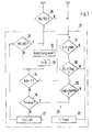
- the in Fig. Step 20 shown in FIG. 3 is part of this query.
- step 20 it is checked whether the rocker switch 4 an upshift or a downshift signal HS / RS has been issued. If this is not the case, the remains Control device 1 in its automatic operating mode, here characterized by the drive level D. Is on the other hand, an upshift or downshift signal HS / RS on, the program becomes manual Short-term influence 21 branches.
- the program 21 begins in its first step 22 with the execution of the upshift or Downshift signal HS / RS requested circuit.
- This first step 22 is an alternative Execution of the method is not provided if the program 21 by a first upshift or Downshift signal HS / RS is initially only to be called without immediately switching is performed.
- a time counter T is reset to the value zero.
- step 24 a kick-down signal kd is requested. If there is such a signal, it becomes Ascent routine 25 branches. Otherwise, the program continues with step 26, where checks are made is whether the counter T has reached its maximum value - here corresponding to a period of 8 seconds. If the maximum value is reached or exceeded, a branch is also made to the ascent routine 25 and otherwise the program continues with step 27 by increasing the time counter T by a time increment dT becomes.
- step 28 it is again checked whether an upshift or downshift signal HS / RS is present. If this is the case, the program flow continues with step 22, while otherwise directly branch to step 24.
- the exit routine 25 consists of three test steps 29 to 31.
- the first test step 29 it is checked whether the signal aqg for the lateral acceleration of the vehicle is less than a preset maximum value aqmax is.
- the signal ZS indicates a train operation of the vehicle.
- step 31 it is checked in step 31 whether the driving speed v of the vehicle is greater than one
- the minimum value vmin from here is 5 km / h.
- step 29 to 31 If the conditions checked in steps 29 to 31 are all met, program 21 is exited. If, on the other hand, one of the three conditions is not met, the time counter T is changed to the value Tmin in step 32 set, which in the present example is a size of 75% of the maximum value checked in step 26 accepts.
- the signal zs of the pull-push detector 18 assumes the value "thrust" when the vehicle is stationary or at low speed (less than 5 km / h) rolls. In normal driving operation, however, the signal zs acts in a manner known per se the position of the throttle valve DK or determined using alternative methods. This results in the Steps 30, 31 the effect that the program 21 with a stationary or rolling vehicle and not accelerator pedal cannot be exited. This makes it possible, for example, to first gear to select as starting gear by actuating the rocker switch 4, while in gear D in automatic mode, the second gear is regularly used as the starting gear.
Landscapes
- Engineering & Computer Science (AREA)
- General Engineering & Computer Science (AREA)
- Mechanical Engineering (AREA)
- Control Of Transmission Device (AREA)
Applications Claiming Priority (2)
| Application Number | Priority Date | Filing Date | Title |
|---|---|---|---|
| DE10052880 | 2000-10-20 | ||
| DE10052880A DE10052880C2 (de) | 2000-10-20 | 2000-10-20 | Vorrichtung und Verfahren zum Steuern eines selbsttätig schaltenden Getriebes |
Publications (3)
| Publication Number | Publication Date |
|---|---|
| EP1199497A2 true EP1199497A2 (fr) | 2002-04-24 |
| EP1199497A3 EP1199497A3 (fr) | 2008-08-27 |
| EP1199497B1 EP1199497B1 (fr) | 2010-11-03 |
Family
ID=7661015
Family Applications (1)
| Application Number | Title | Priority Date | Filing Date |
|---|---|---|---|
| EP01119388A Expired - Lifetime EP1199497B1 (fr) | 2000-10-20 | 2001-08-11 | Méthode et dispositif de commande d'une boîte de vitesses automatisée |
Country Status (5)
| Country | Link |
|---|---|
| US (1) | US6622581B2 (fr) |
| EP (1) | EP1199497B1 (fr) |
| JP (1) | JP3754637B2 (fr) |
| KR (1) | KR100895945B1 (fr) |
| DE (2) | DE10052880C2 (fr) |
Families Citing this family (15)
| Publication number | Priority date | Publication date | Assignee | Title |
|---|---|---|---|---|
| DE10311638A1 (de) * | 2003-03-14 | 2004-10-14 | Conti Temic Microelectronic Gmbh | Kraftfahrzeug |
| JP2005170247A (ja) * | 2003-12-11 | 2005-06-30 | Alps Electric Co Ltd | ギアシフト装置 |
| DE102004021013A1 (de) * | 2004-04-29 | 2005-11-24 | Zf Friedrichshafen Ag | Verfahren zum Steuern eines Getriebes eines Kraftfahrzeugs |
| DE102004028705B3 (de) * | 2004-06-14 | 2006-02-09 | Siemens Ag | Verfahren zur Steuerung eines Automatikgetriebes |
| DE102004057724A1 (de) * | 2004-11-30 | 2006-06-01 | Bayerische Motoren Werke Ag | Vorrichtung zum Steuern eines automatisch schaltenden Getriebes |
| JP4188360B2 (ja) * | 2005-10-31 | 2008-11-26 | 本田技研工業株式会社 | 自動変速機の変速制御装置 |
| JP4283264B2 (ja) | 2005-10-31 | 2009-06-24 | 本田技研工業株式会社 | 自動変速機の変速制御装置 |
| JP4188359B2 (ja) | 2005-10-31 | 2008-11-26 | 本田技研工業株式会社 | 自動変速機の変速制御装置 |
| JP4740719B2 (ja) * | 2005-11-08 | 2011-08-03 | 本田技研工業株式会社 | 自動変速機の変速制御装置 |
| JP5186742B2 (ja) * | 2006-08-25 | 2013-04-24 | 日産自動車株式会社 | 自動変速機のモード切り替え制御装置 |
| DE102007035297A1 (de) | 2007-07-27 | 2009-01-29 | Zf Friedrichshafen Ag | Verfahren zur Steuerung eines Automatgetriebes eines Kraftfahrzeuges |
| JP4281832B2 (ja) | 2007-10-25 | 2009-06-17 | トヨタ自動車株式会社 | 自動変速機の制御装置 |
| JP4978490B2 (ja) * | 2008-02-04 | 2012-07-18 | マツダ株式会社 | 自動変速機の制御装置 |
| US10650623B2 (en) * | 2018-09-18 | 2020-05-12 | Avinew, Inc. | Detecting of automatic driving |
| JP7780356B2 (ja) * | 2022-02-24 | 2025-12-04 | 株式会社Subaru | 変速モード制御システム |
Citations (2)
| Publication number | Priority date | Publication date | Assignee | Title |
|---|---|---|---|---|
| DE4311886A1 (de) | 1993-04-10 | 1994-10-13 | Porsche Ag | Vorrichtung und Verfahren zum Steuern eines selbsttätig schaltenden Getriebes |
| DE19912963A1 (de) | 1999-03-23 | 2000-09-28 | Porsche Ag | Vorrichtung und Verfahren zum Steuern eines selbsttätig schaltenden Getriebes |
Family Cites Families (1)
| Publication number | Priority date | Publication date | Assignee | Title |
|---|---|---|---|---|
| DE19736406B4 (de) * | 1997-08-21 | 2007-05-16 | Siemens Ag | Einrichtung zum Steuern eines automatischen Getriebes für ein Kraftfahrzeug |
-
2000
- 2000-10-20 DE DE10052880A patent/DE10052880C2/de not_active Expired - Fee Related
-
2001
- 2001-08-11 EP EP01119388A patent/EP1199497B1/fr not_active Expired - Lifetime
- 2001-08-11 DE DE50115687T patent/DE50115687D1/de not_active Expired - Lifetime
- 2001-09-07 JP JP2001272273A patent/JP3754637B2/ja not_active Expired - Fee Related
- 2001-10-16 KR KR1020010063545A patent/KR100895945B1/ko not_active Expired - Fee Related
- 2001-10-19 US US09/982,235 patent/US6622581B2/en not_active Expired - Lifetime
Patent Citations (2)
| Publication number | Priority date | Publication date | Assignee | Title |
|---|---|---|---|---|
| DE4311886A1 (de) | 1993-04-10 | 1994-10-13 | Porsche Ag | Vorrichtung und Verfahren zum Steuern eines selbsttätig schaltenden Getriebes |
| DE19912963A1 (de) | 1999-03-23 | 2000-09-28 | Porsche Ag | Vorrichtung und Verfahren zum Steuern eines selbsttätig schaltenden Getriebes |
Non-Patent Citations (3)
| Title |
|---|
| CH-Z "Automobil Revue" Heft 51/1992, Seite 23 |
| DE-Z "Auto Motor Sport" Heft 22/1991, Seite 300. |
| DE-Z "Automobiltechnische Zeitschrift" Heft 6/1990, Seite 308 bis 319 |
Also Published As
| Publication number | Publication date |
|---|---|
| EP1199497B1 (fr) | 2010-11-03 |
| JP3754637B2 (ja) | 2006-03-15 |
| DE10052880C2 (de) | 2002-11-28 |
| KR100895945B1 (ko) | 2009-05-07 |
| US20020046894A1 (en) | 2002-04-25 |
| DE50115687D1 (de) | 2010-12-16 |
| DE10052880A1 (de) | 2002-05-08 |
| EP1199497A3 (fr) | 2008-08-27 |
| JP2002147588A (ja) | 2002-05-22 |
| US6622581B2 (en) | 2003-09-23 |
| KR20020031037A (ko) | 2002-04-26 |
Similar Documents
| Publication | Publication Date | Title |
|---|---|---|
| DE19912963B4 (de) | Vorrichtung und Verfahren zum Steuern eines selbsttätig schaltenden Getriebes | |
| DE4311886C2 (de) | Vorrichtung und Verfahren zum Steuern eines selbsttätig schaltenden Getriebes | |
| DE4112577C2 (de) | Steuerungsvorrichtung für automatische Getriebe | |
| DE3341652C2 (fr) | ||
| EP1390647B1 (fr) | Procede pour commander une boite de vitesses automatique d'un vehicule automobile | |
| DE3139838C2 (de) | Steuervorrichtung für ein Automatikgetriebe in einem Kraftfahrzeug | |
| DE4120603C2 (de) | Steuereinrichtung für ein selbsttätig schaltendes Getriebe eines Kraftfahrzeugs | |
| DE10052880C2 (de) | Vorrichtung und Verfahren zum Steuern eines selbsttätig schaltenden Getriebes | |
| DE3201440C2 (fr) | ||
| EP0713985B1 (fr) | Dispositif et méthode de commande d'une transmission à variation continue | |
| DE19849059A1 (de) | Verfahren zur Steuerung eines Automatgetriebes eines Kraftfahrzeuges bei einer spontanen Gas-/Pedalrücknahme | |
| DE69804328T2 (de) | Schaltvorrichtung für ein stufenloses getriebe eines kraftfahrzeuges | |
| DE19643161A1 (de) | Steuervorrichtung für stufenlos veränderliches Getriebe | |
| DE4028833C2 (de) | Betriebsarten-Steuersystem für ein Automatikgetriebe | |
| EP1199498A2 (fr) | Dispositif de commande pour transmission d'un véhicule automobile | |
| DE102006050314B4 (de) | Schaltsteuervorrichtung für Automatikgetriebe | |
| EP0634591B1 (fr) | Méthode et dispositif de commande d'une boíte de vitesses automatique | |
| EP1123473B1 (fr) | Procede de regulation d'une boite de vitesses automatique | |
| DE4120566C2 (de) | Steuereinrichtung für ein selbsttätig schaltendes Getriebe eines Kraftfahrzeugs | |
| DE69302797T2 (de) | Steuervorrichtung für ein automatisiertes Getriebe eines Nutzfahrzeuges | |
| DE102006050358B4 (de) | Schaltsteuervorrichtung für ein Automatikgetriebe | |
| DE102006050325B4 (de) | Schaltsteuervorrichtung für ein Automatikgetriebe | |
| DE69809236T2 (de) | Verfahren zum steuern der zurückschaltungsgänge bei automatikgetrieben | |
| DE4006062C2 (de) | Schaltsteuereinrichtung für ein automatisches Getriebe eines Kraftfahrzeuges | |
| DE19826861C1 (de) | Verfahren und Vorrichtung zum Steuern eines automatisch schaltbaren Getriebes eines Kraftfahrzeuges |
Legal Events
| Date | Code | Title | Description |
|---|---|---|---|
| PUAI | Public reference made under article 153(3) epc to a published international application that has entered the european phase |
Free format text: ORIGINAL CODE: 0009012 |
|
| AK | Designated contracting states |
Kind code of ref document: A2 Designated state(s): AT BE CH CY DE DK ES FI FR GB GR IE IT LI LU MC NL PT SE TR |
|
| AX | Request for extension of the european patent |
Free format text: AL;LT;LV;MK;RO;SI |
|
| RAP1 | Party data changed (applicant data changed or rights of an application transferred) |
Owner name: DR. ING. H.C. F. PORSCHE AKTIENGESELLSCHAFT |
|
| RAP1 | Party data changed (applicant data changed or rights of an application transferred) |
Owner name: DR. ING. H.C. F. PORSCHE AKTIENGESELLSCHAFT |
|
| PUAL | Search report despatched |
Free format text: ORIGINAL CODE: 0009013 |
|
| AK | Designated contracting states |
Kind code of ref document: A3 Designated state(s): AT BE CH CY DE DK ES FI FR GB GR IE IT LI LU MC NL PT SE TR |
|
| AX | Request for extension of the european patent |
Extension state: AL LT LV MK RO SI |
|
| 17P | Request for examination filed |
Effective date: 20090227 |
|
| AKX | Designation fees paid |
Designated state(s): DE FR GB IT |
|
| 17Q | First examination report despatched |
Effective date: 20090605 |
|
| RAP1 | Party data changed (applicant data changed or rights of an application transferred) |
Owner name: DR. ING. H.C. F. PORSCHE AG |
|
| GRAP | Despatch of communication of intention to grant a patent |
Free format text: ORIGINAL CODE: EPIDOSNIGR1 |
|
| GRAS | Grant fee paid |
Free format text: ORIGINAL CODE: EPIDOSNIGR3 |
|
| GRAA | (expected) grant |
Free format text: ORIGINAL CODE: 0009210 |
|
| AK | Designated contracting states |
Kind code of ref document: B1 Designated state(s): DE FR GB IT |
|
| REG | Reference to a national code |
Ref country code: GB Ref legal event code: FG4D Free format text: NOT ENGLISH |
|
| REF | Corresponds to: |
Ref document number: 50115687 Country of ref document: DE Date of ref document: 20101216 Kind code of ref document: P |
|
| PLBE | No opposition filed within time limit |
Free format text: ORIGINAL CODE: 0009261 |
|
| STAA | Information on the status of an ep patent application or granted ep patent |
Free format text: STATUS: NO OPPOSITION FILED WITHIN TIME LIMIT |
|
| 26N | No opposition filed |
Effective date: 20110804 |
|
| PGFP | Annual fee paid to national office [announced via postgrant information from national office to epo] |
Ref country code: GB Payment date: 20110819 Year of fee payment: 11 |
|
| REG | Reference to a national code |
Ref country code: DE Ref legal event code: R097 Ref document number: 50115687 Country of ref document: DE Effective date: 20110804 |
|
| PG25 | Lapsed in a contracting state [announced via postgrant information from national office to epo] |
Ref country code: IT Free format text: LAPSE BECAUSE OF NON-PAYMENT OF DUE FEES Effective date: 20110811 |
|
| GBPC | Gb: european patent ceased through non-payment of renewal fee |
Effective date: 20120811 |
|
| PG25 | Lapsed in a contracting state [announced via postgrant information from national office to epo] |
Ref country code: GB Free format text: LAPSE BECAUSE OF NON-PAYMENT OF DUE FEES Effective date: 20120811 |
|
| REG | Reference to a national code |
Ref country code: FR Ref legal event code: PLFP Year of fee payment: 16 |
|
| PGFP | Annual fee paid to national office [announced via postgrant information from national office to epo] |
Ref country code: DE Payment date: 20160801 Year of fee payment: 16 |
|
| PGFP | Annual fee paid to national office [announced via postgrant information from national office to epo] |
Ref country code: FR Payment date: 20160822 Year of fee payment: 16 |
|
| REG | Reference to a national code |
Ref country code: DE Ref legal event code: R119 Ref document number: 50115687 Country of ref document: DE |
|
| REG | Reference to a national code |
Ref country code: FR Ref legal event code: ST Effective date: 20180430 |
|
| PG25 | Lapsed in a contracting state [announced via postgrant information from national office to epo] |
Ref country code: DE Free format text: LAPSE BECAUSE OF NON-PAYMENT OF DUE FEES Effective date: 20180301 |
|
| PG25 | Lapsed in a contracting state [announced via postgrant information from national office to epo] |
Ref country code: FR Free format text: LAPSE BECAUSE OF NON-PAYMENT OF DUE FEES Effective date: 20170831 |