EP1200208B1 - Maschine zur behandlung von gegenständen - Google Patents
Maschine zur behandlung von gegenständen Download PDFInfo
- Publication number
- EP1200208B1 EP1200208B1 EP00946030A EP00946030A EP1200208B1 EP 1200208 B1 EP1200208 B1 EP 1200208B1 EP 00946030 A EP00946030 A EP 00946030A EP 00946030 A EP00946030 A EP 00946030A EP 1200208 B1 EP1200208 B1 EP 1200208B1
- Authority
- EP
- European Patent Office
- Prior art keywords
- treatment
- machine according
- gripping
- loading
- containers
- Prior art date
- Legal status (The legal status is an assumption and is not a legal conclusion. Google has not performed a legal analysis and makes no representation as to the accuracy of the status listed.)
- Expired - Lifetime
Links
Images



Classifications
-
- B—PERFORMING OPERATIONS; TRANSPORTING
- B67—OPENING, CLOSING OR CLEANING BOTTLES, JARS OR SIMILAR CONTAINERS; LIQUID HANDLING
- B67C—CLEANING, FILLING WITH LIQUIDS OR SEMILIQUIDS, OR EMPTYING, OF BOTTLES, JARS, CANS, CASKS, BARRELS, OR SIMILAR CONTAINERS, NOT OTHERWISE PROVIDED FOR; FUNNELS
- B67C7/00—Concurrent cleaning, filling, and closing of bottles; Processes or devices for at least two of these operations
-
- B—PERFORMING OPERATIONS; TRANSPORTING
- B08—CLEANING
- B08B—CLEANING IN GENERAL; PREVENTION OF FOULING IN GENERAL
- B08B9/00—Cleaning hollow articles by methods or apparatus specially adapted thereto
- B08B9/08—Cleaning containers, e.g. tanks
- B08B9/20—Cleaning containers, e.g. tanks by using apparatus into or on to which containers, e.g. bottles, jars, cans are brought
- B08B9/42—Cleaning containers, e.g. tanks by using apparatus into or on to which containers, e.g. bottles, jars, cans are brought the apparatus being characterised by means for conveying or carrying containers therethrough
- B08B9/426—Grippers for bottles
Definitions
- the invention relates to a processing machine objects, in particular hollow bodies such as containers or container preforms according to the preamble of claim 1.
- the invention relates more particularly to the field of object-processing machines in which a series of treatment are mobile according to a path according to a loop circuit, for example by being attached to a rotating carousel training or endless training chain, and each include a system of grasping device to take over an object at a point of loading and return it to an unloading point on the route. Between its point of loading and unloading, an object is moved relative to the station, by the gripping system, from an initial position loading at at least one treatment position and at a position final unloading. Moreover, the machine comprises devices processing objects supported by each post.
- a machine of this type, intended for the treatment of containers, is for example described in EP-A-0.477.341.
- the machine described in this document allows only one treatment of each container, at least if you want to keep a pace important operation of the machine.
- the time of stay of a container on the machine is inversely proportional to the number of treated containers for a given period of time, and this residence time is anyway less than the time required for the carousel to perform a rotation.
- the useful processing time is still limited by the the time required for loading, unloading, and both spills of each container.
- Another type of known processing machine is constituted by the furnaces for heating or thermal conditioning of preforms or of blanks for containers in container-making plants by blowing or stretching then blowing of preforms heated, such as installations of the type described in the patent French FR-2.479.077.
- preforms or blanks follow a circuit in looping path being carried by rotating grip systems and, while being rotated on themselves in warming zones with heating elements and reflectors.
- preforms or blanks are introduced at the top, and then have been returned to be warmed with their collar down to avoid that it does not warm up too much and then deforms during the operation subsequent blowing, and are returned a second time to allow blowing containers neck up.
- the residence time of a preform on the machine is inversely proportional to the number of preforms processed for a given duration, and the useful time of reheating or conditioning is still limited the time required for loading, unloading, and both flips of each preform.
- the object of the invention is to propose a machine particularly compact and economical in order to be able to perform treatments of high-speed objects.
- the invention provides an object processing machine according to claim 1.
- the invention makes it possible to keep each object on a respective post for a longer travel time than is necessary for the job to complete a complete tour of the circuit. It is therefore possible to do to pass several times the same object at the same point of the path, however, by changing the position of the gripping unit, so the spatial position of the object.
- a machine according to the invention can be used to perform several successive treatments, without being more cumbersome that a machine of the prior art which was only a single treatment, and of course, without reducing the pace. We can thus perform, in a same space for rinsing and cleaning of objects.
- the invention can be applied by example, quite advantageous to the machines for rinsing and disinfect containers, especially polyethylene bottles terephthalate (PET), with a view to filling them with a liquid which can be food, or even machines intended to rinse and disinfect blanks of such containers, called preforms.
- PET polyethylene bottles terephthalate
- blow molding machines such blow molding machines preforms, specifically in thermal conditioning furnaces such preforms located upstream of the molding devices blowing.
- the following description illustrates more specifically the treatment objects consisting of hollow bodies, such as containers (bottles, bottles or other) or preforms of containers.
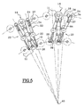
- FIGS. 1 and 2 illustrate the principle of a machine for treatment of objects both compact and capable of high rates.
- This machine comprises a series of stations 12 which perform a looping path.
- all items 12 are integral with a circular carousel 10 which is rotated by continuous way around its axis A0.
- the invention could also be implemented in positions related to each other according to the principle of a chain without end of training.
- the principle of this machine is to keep each object on a respective post for a period longer than that required by the post to complete a complete tour of his circuit. In the occurrence the object remains on the station for almost two turns.
- the illustrated machine is therefore a rotary machine whose axis of rotation will be qualified as vertical for the sake of clarity.
- the carousel 10 has a series of stations 12 which are distributed angularly around the axis A0 and which are each intended to carry 11.
- each station 12 can carry two bottles.
- the invention may also be work with posts that can each support more than bottles.
- Each station comprises a gripping unit 14 of bottles which is mobile with respect to the station, so with respect to the carousel, and which comprises in this case two gripping systems 16 each take charge of a bottle.
- it is about tongs that can grab a PET bottle by the collar, these tongs being preferably tongs whose opening and closing are controlled by a specific mechanism, this mechanism to avoid any risk of openness accidental of the clamp when the bottle is being processed, these clamps also allow to leave open the bottles to allow the introduction of a rinsing or cleaning product when the machine is intended for such functions.
- Each gripping unit 14 is rotatably mounted by report to his post 12 around an axis An which is tangent to the trajectory of the post.
- each gripping unit is designed to be able to occupy two opposite positions at 180 degrees around the An axis.
- the unit can occupy at least as many different discrete positions that the unit can wear from bottles. In any case, the number of positions for one unit be greater than the number of bottles.
- the gripping systems 16 are arranged in such a way that the bottles carried by the same unit are arranged along two axes parallel vertical lines, symmetrically on both sides of the An axis and the bottles being of course in opposite direction to each other. So when one of the bottles is oriented with its open end upward, the open end of the other bottle is facing the low.
- the clips 16 are offset according to the direction of the axes of the bottles and they are arranged on the else of the An axis so that whoever wears the bottle collar down is located below the level of the one wearing the neck collar at the top. By this arrangement, it reduces the free space necessary for the reversal of the gripping unit when carrying the bottles.
- the gripping unit 14 is entirely symmetrical relative to the An axis. Due to the geometry of the gripping unit 14, each clip is brought to meet alternately in a external radial position and in an internal radial position with respect to the axis A0 of the carousel. In one case, the bottle she is carrying is oriented neck down, here when the clamp is in the outer radial position. In position radial internal, it is oriented neck up. Whatever the position of the gripping unit 14, the axes of the bottles are all substantially in the same radial plane containing the axis A0 of rotation of the carousel and perpendicular to the axis An rotation of the unit 14 considered.
- conveyor systems 15, of known type bring the containers 11 so tangent to a loading point of the carousel whose position is fixed around the axis A0.
- the bottle is supported, neck down, by the outer gripper of a gripping unit.
- each station supports a container by grabbing it by the clamp which, at this moment, is in external radial position.
- the bottle is then rotated around the A0 axis, by the carousel, for about half a turn, until arrive at a turning point.
- the gripping unit 14 is rotated about its axis An 180 degrees. Of this way, the bottle which was initially in radial position external with the neck downward undergoes a displacement that brings it to a radial position internal with the collar at the top.
- each gripping unit 16 has two arms 18 which extend symmetrically in a plane perpendicular to the An axis.
- Each arm 18 has a U-shaped end which, during the rotation of the carousel, is intended to follow a fixed section of the machine.
- each profile 20 extends according to a section of a helix wound on a toric surface.
- Such a means of to control the reversal is analogous to that described in the document EP-A-0.477.341 and it is noted that, thus ordered, the unit of processing 14 always rotates in the same direction around its axis An.
- other means may be used, such as actuators motorized.
- each gripping unit 14 is brought to occupy only two positions and only one sector of turnaround. In this way, a bottle that has just been taken care of on the carousel, which has just been returned, is obliged to perform a complete turn in internal radial position. As part of a treatment of cleaning and disinfection, this duration allows to give the agent sterilizing a sufficient time of action. However, we could consider machine having for example three turning sectors. Similarly, one could expect to bring the gripping unit into a number intermediate positions.
- the bottle At the end of its turn in the internal radial position, the bottle is again brought back to the outer radial position by the gripping unit. She then made about a turn and a half around the A0 axis since her loading on the carousel.
- the gripping unit occupies only two discrete discrete positions. Also, the initial positions of loading and final unloading of a bottle are the same. However, could consider that these two positions of the bottle are different.
- the relative duration of the various stages of treatment also depends on the location of the sector (s) of turnaround from the circuit. So, starting from the illustrated example in Figures 1 and 2, it would be possible to reduce the duration of the first rinsing by arranging the turning area closer to the point of loading bottles. Correlatively, the duration of the final rinse would be increased. At the limit, it may be possible to achieve only two stages of treatment by arranging the turning sector immediately near the point of loading or the point of unloading.
- the invention therefore offers great flexibility.
- each gripping unit 14 does not comprises only two gripping systems 16 so that each container performs a fraction of numbers of carousel turn included between 1 and 2.
- each container could perform on the carousel between 2 and 3 turns.
- the machine according to the invention also comprises treatment 22 able to project inside the bottle liquids, such only water or a sterilizing agent. Eventually, we could also provide for the projection of a gas, or any other agent.
- each device has two projection spouts: an external spout 24 which is susceptible to project, upwards, a rinsing agent, here liquid, inside a bottle arranged at the bottom in a radial position outside, and a beak internal 26 which can project, downward, the sterilizing agent inside of a bottle arranged neck up in radial internal position.
- an external spout 24 which is susceptible to project, upwards, a rinsing agent, here liquid, inside a bottle arranged at the bottom in a radial position outside
- a beak internal 26 which can project, downward, the sterilizing agent inside of a bottle arranged neck up in radial internal position.
- each device 22 is mobile between a unobstructed position and an active position. Indeed, each device 22 is arranged at the top of a vertical column 28 which, with respect to the axis A0, is located radially between the outer circle and the inner circle of the trajectory of the bottles.
- the two beaks 24, 26 are rotatably mounted about the axis of column 28, preferably by means of a rotary coupling 30 which makes it possible to connect the nozzles 24, 26 to product distribution circuits 32 of the machine. Both nozzles 24, 26 extend away from each other with respect to the column 28.
- the processing devices 22 are the same number as the units 14 and they are interposed angularly between the positions 12.
- the two spouts 24, 26 are oriented substantially in a radial plane containing the axis A0 so as not to interfere with the gripping units 14 adjacent, nor with the bottles that they carry. In this position, they do not hinder the reversal of bottles.
- the two nozzles In the active position, the two nozzles have pivoted about the axis column 28, so that the internal beak 26 is view of the opening of a cylinder in an internal radial position on one two posts adjacent to the device 22. The external nozzle 24 is then in view of the opening of a bottle in radial external position on the other two adjacent stations.
- a device 22 can therefore process at the same time two bottles projecting into one of the rinsing liquid and into the other a sterilizing agent.
- the device For the proper functioning of the machine, it However, the device must be returned to the unobstructed level of the angular reversal sector, and, on the other hand, at of the angular sector along which the unloading and loading bottles.
- the external nozzle 24 which projects rinse liquid in a bottle arranged neck down, is received coaxially in a tubular recovery pipe 34 which the open end is next to the neck of the bottle when the device is in the active position.
- the recovery line 34 can thus harvest the flushing liquid that flows from the bottle and discharges it via the fitting turn 30, to the dispensing circuits of the machine.
- the internal beak 24 and the recovery pipe 34 are integral with one of the other.
- the devices 22 comprise means for avoiding project product on the machine if there is no bottle on one of the positions.
- the external nozzle 24 has a movable baffle 36 which, when there is no bottle, is right next to the spout 24 and the recovery pipe 34.
- the liquid projected by the spout 24 is returned directly to the recovery line.
- the deflector 36 is arranged at the end of an arm 37 which can pivot relative to spout 24 and pipe 34 around a vertical axis parallel to the pivot axis of the latter.
- the deflector 36 is provided to come to bear on the neck of the bottle, if there is one. In that case, the deflector 36 pivots with respect to the spout 24, which continues its course towards its active position opposite the open end of the bottle.
- the deflector is removed from the beak and does not disturbed by the projection of liquid.
- the deflector 36 does not meet no bearing surface and remains facing the nozzle 24, which is its position habitual way to which it is brought back by elastic means (no shown).
- the internal spout 26 is equipped with a tubing of recovery 38 which, in the absence of a bottle, is just opposite the 26.
- the tubing 38 In the presence of a bottle, the tubing 38 is discarded in pivoting by the neck of the bottle when the device 22 passes its open position at its active position.
- the machine thus proposed is therefore particularly simple and compact, while allowing to implement a complete process of cleaning and sterilization of the container.
- the invention finds another application particularly advantageous for heating preforms or of blanks for containers in container-making plants made of plastic, by blowing or stretching and then blowing such preforms or blanks.
- Figure 6 is a schematic illustration.
- the machine has a series of 120 stations that perform a looping path.
- all the stations 120 are integral with a circular carousel 100 which is rotated in a continuous manner about its axis A10 vertical.
- the invention could also be implemented in the positions linked to each other according to the principle of a chain link.
- the stations 120 which are angularly distributed around the axis A10 and are each intended to bear several, in the example shown in two, preforms 110 or blanks of containers
- Each station comprises a gripping unit 140 of preforms 110 or blanks of containers that is movable relative to the station, so compared to the carousel, and which involves in this case two systems 160 each capable of supporting a preform 110 or container blank.
- Each gripping system 160 comprises of a part of the input means, not illustrated in detail, but known per se, of a preform 110 or container blank, and means for enabling the rotation of the preforms 110 about their longitudinal axis at least when the preforms are in a reheating zone.
- the input means are for example constituted by mandrel-type mechanisms that grip the inside or outside of the neck preforms, and the means for rotating the preforms on they themselves are mechanically linked to the input means.
- Setting rotation is for example using chain mechanisms and sprockets, known per se and not shown.
- each gripping unit 140 is rotatably mounted relative to its station 120 around a axis that is tangent to the trajectory of the station.
- each unit gripper is provided to occupy two positions opposite to 180 degrees around this axis.
- the gripping unit 140 is symmetrical with respect to the tangent axis to the trajectory of the post. Due to the geometry of the unit of gripping 140, each preform is brought to meet alternately oriented in a neck down position and in a position collar at the top.
- Suitable conveyor systems 150 lead to preforms 110 or container blanks, neck up, so tangent to a loading point of the carousel whose position is fixed around the axis A10. At this point, each preform is supported, by the gripping means of a gripping unit. As and when the rotation of the carousel, at each passage through the loading point, each station supports a preform 110. Once supported by a gripping unit 140, each preform 110 is then driven in rotation around the axis A10, by the carousel, on almost one, half-turn in the illustrated example, until, arrive at a turning sector.
- the gripping unit 140 is rotated around its axis tangent to the trajectory of the post on 180 degrees. In this way, the preform that was initially in position with the neck upwards undergoes a shift that brings it to an internal radial position with the collar at the bottom.
- Means similar or identical to those described with regard to FIGS. 1 to 5, such as profiles, can be used to ensure the reversal, always in the same direction, on the one hand and the maintenance in fixed position of the gripping units on the other hand. They will not be described in more detail.
- each gripping unit 140 is occupies only two positions and only one sector is planned reversal.
- the preform is again brought back to the neck position at the top by the gripping unit. She has then performed about a turn and a half around the A10 axis since his loading on the carousel.
- the gripping unit since the gripping unit only occupies two discrete discrete positions, the initial positions of loading and final unloading of a preform are the same. However, could consider that these of their preform positions are different, especially in installations in which preforms are introduced neck up, and the blowing of the containers is done with the collar down.
- the treatment consists of reheating of preforms 110, and processing devices 220, 221, consisting of heating means of the preforms 110, whose structure is known per se, are attached to the frame of the machine and are arranged appropriate way in the areas between the loading area 150 and the turnaround area on the one hand, as well as between the turnaround and unloading zone on the other hand, so as to heat the preforms that pass in front of these means, that they are with their collar up or down.
- these means of heating are constituted by lamps and reflectors.
- the reheating takes place in two carousel towers, and it is easy to imagine that it is possible to reduce the circumference of the carousel in a ratio of approximately two to achieve the same result, in terms of rates and efficiency, than with a conventional machine. It is therefore possible to reduce considerably the size of a manufacturing facility containers.
- the relative duration of the various stages of Heating depends on the location of the turning sector (s) compared to the circuit.
- the preforms perform, after their loading, almost a half-circuit circuit where they are warmed up at the top, then a neck down turn, and finally almost a half turn again collar at the top.
- the invention is therefore particularly advantageous in this type particular application, since it makes it possible to reduce the footprint of reheating furnaces; in addition, it optimizes the heating thanks to the positioning possibilities of the neck or collar preforms below.
Landscapes
- Mechanical Engineering (AREA)
- Engineering & Computer Science (AREA)
- Blow-Moulding Or Thermoforming Of Plastics Or The Like (AREA)
- Filling Of Jars Or Cans And Processes For Cleaning And Sealing Jars (AREA)
- Threshing Machine Elements (AREA)
- Disintegrating Or Milling (AREA)
- Formation And Processing Of Food Products (AREA)
- Cleaning By Liquid Or Steam (AREA)
- Cleaning In General (AREA)
- Specific Conveyance Elements (AREA)
- Electrical Discharge Machining, Electrochemical Machining, And Combined Machining (AREA)
- Control And Other Processes For Unpacking Of Materials (AREA)
- Manipulator (AREA)
- Encapsulation Of And Coatings For Semiconductor Or Solid State Devices (AREA)
Claims (21)
- Maschine zum Behandeln von Objekten (11; 110), insbesondere von Hohlkörpern, wie zum Beispiel Behälter oder Vorformen von Behältern, des Typs, der eine Reihe von Posten (12; 120) umfasst, die gemäß einem Verlauf auf einem Kreislauf in Schleife beweglich sind, und von welchen jeder ein Greifsystem (16; 160) umfasst, das dazu bestimmt ist, ein Objekt (11; 110) an einem Ladepunkt zu übernehmen und es an einem Entladepunkt des Verlaufs zurückzugeben, des Typs, bei dem das Objekt (11; 110) zwischen dem Ladepunkt und dem Entladepunkt in Bezug zum Posten (12; 120) von dem Greifsystem (16; 160) von einer Ausgangsladestellung in mindestens eine Behandlungsstellung und dann in eine abschließende Entladestellung bewegt wird, des Typs, bei dem die Maschine Behandlungsvorrichtungen (22; 220; 221) der von jedem Posten übernommenen Objekte umfasst, des Typs, bei dem jeder Posten mit einer Greifeinheit (14; 140) versehen ist, die mindestens zwei Greifsysteme (16; 160) umfasst, und des Typs, bei dem die Greifeinheit (14; 140) in Bezug zum Posten zwischen mindestens einer ersten Stellung, bei der sich ein erstes Objekt, das von einem ersten System (16; 160) der Einheit (14; 140) getragen wird, in seiner Anfangsstellung befindet, während ein zweites von einem zweiten System (16; 160) der Einheit (14; 140) getragenes Objekt in einer Behandlungsstellung ist, und einer letzten Stellung beweglich ist, bei der sich das erste Objekt in einer Behandlungsstellung befindet, während sich das zweite Objekt in seiner Endstellung befindet, dadurch gekennzeichnet, dass zwischen dem Laden und dem Entladen eines Objekt der von diesem verfolgte Verlauf eine Anzahl von Runden des Kreislaufs umfasst, die zwischen der Anzahl von Greifsystemen (16; 160) jeder Behandlungseinheit (14; 140) und der unmittelbar darunter liegenden ganzen zahl liegt.
- Behandlungsmaschine nach Anspruch 1, dadurch gekennzeichnet, dass jede Greifeinheit (14; 140) bei jeder Passage vor dem Ladepunkt ein Objekt übernehmen kann.
- Behandlungsmaschine nach einem der vorhergehenden Ansprüche, dadurch gekennzeichnet, dass jede Greifeinheit (14; 140) in Drehung zu dem Posten (12; 120), der um eine Achse (An) zugewiesen ist, die in einem gegebenen Punkt zu der Verlaufsrichtung des Postens (12; 120) zu diesem Punkt tangierend ist, beweglich ist.
- Behandlungsmaschine nach einem der vorhergehenden Ansprüche, dadurch gekennzeichnet, dass jede Greifeinheit (14; 140) sequenziell zwischen mindestens ebenso vielen diskreten Stellungen beweglich ist wie jede Greifeinheit (14; 140) Greifsysteme (16; 160) umfasst.
- Behandlungsmaschine nach einem der Ansprüche 1 bis 4, dadurch gekennzeichnet, dass die Anfangsstellung und die Endstellung jedes Objekts (11; 110) zu dem Posten, welcher es trägt, identisch sind,
- Behandlungsmaschine nach einem der Ansprüche 1 bis 5, dadurch gekennzeichnet, dass die Posten (12; 120) fest mit einer Antriebsvorrichtung verbunden sind, die aus einem Drehkarussell (10; 100) der Maschine besteht.
- Behandlungsmaschine nach einem der Ansprüche 1 bis 5, dadurch gekennzeichnet, dass die Posten (12; 120) fest mit einer Antriebsvorrichtung verbunden sind, die aus einer Endloskette besteht.
- Behandlungsmaschine nach einem der Ansprüche 6 oder 7, dadurch gekennzeichnet, dass sie zur Behandlung von Behältern (11) bestimmt ist, und dadurch, dass jede Greifeinheit (14) zwei Greifsysteme (16) umfasst, wobei jedes einen Behälter im Wesentlichen an seinem offenen Ende trägt, dadurch, dass die Behälter in umgekehrte Richtungen gemäß zwei parallelen Achse angeordnet sind, die in einer radialen Ebene der Antriebsvorrichtung enthalten und zu beiden Seiten der Drehachse (An) der Einheit (14) versetzt sind, und dadurch, dass die Stellungen der zwei Behälter gemäß der Richtung ihrer Achsen einander teilweise überlagern.
- Behandlungsmaschine nach Anspruch 8, dadurch gekennzeichnet, dass die Behälter in der Anfangsstellung und in der Endstellung in senkrechter Stellung mit dem offenen Ende nach unten gekehrt sind, um eine erste und eine letzte Spülbehandlung zu erhalten.
- Behandlungsmaschine gemäß einem der Ansprüche 8 oder 9, dadurch gekennzeichnet, dass die Behälter in Behandlungsstellung in senkrechter Stellung mit dem offenen Ende nach oben gerichtet sind, um eine Reinigungszwischenbehandlung zu erhalten, im Laufe welcher ein Reinigungsprodukt in den Behälter eingespritzt wird.
- Behandlungsmaschine nach einem der Ansprüche 1 bis 10, dadurch gekennzeichnet, dass die Behandlungsvorrichtungen (22) dem Verlauf der Posten (12) folgen, und dadurch, dass jede Vorrichtung (22) zu den benachbarten Posten (12) zwischen einer frei gefahrenen Stellung und einer aktiven Stellung, in welche sie mit mindestens einem der von einer der Greifeinheiten (14) getragenen Objekte zusammenwirken kann, beweglich ist.
- Behandlungsmaschine nach Anspruch 11, dadurch gekennzeichnet, dass jede Behandlungsvorrichtung (22) mindestens zwei Behandlungsmittel (24, 26) umfasst, wobei jedes dazu bestimmt ist, mit einem Objekt zusammenzuwirken, wobei die zwei Objekte jeweils von zwei benachbarten Posten (12) getragen werden.
- Behandlungsmaschine nach den Ansprüchen 5 und 12 kombiniert, dadurch gekennzeichnet, dass die Behandlungsvorrichtungen (22) in Drehung zu dem Karussell (10; 100) um eine im Wesentlichen zu der Drehachse (A0) des Karussells parallele Achse beweglich sind.
- Behandlungsmaschine nach Anspruch 13, dadurch gekennzeichnet, dass die Greifeinheiten (14) und die Behandlungsvorrichtungen (22) im Wesentlichen auf einem gleichen Kreis um die Drehachse (A0) des Karussells angeordnet sind, und dadurch, dass jede Behandlungsvorrichtung (22) zwischen zwei benachbarte Greifeinheiten (14) eingefügt ist, und dadurch, dass jede Behandlungsvorrichtung (22) in aktiver Stellung mit Objekten der zwei benachbarten Einheiten, welche sie umgeben, zusammenwirkt.
- Behandlungsmaschine nach den Ansprüchen 6 und 12 kombiniert, dadurch gekennzeichnet, dass die Behandlungsvorrichtungen (22) in Drehung zu der Endloskette um eine im Wesentlichen zu der Hauptebene der Endloskette senkrecht stehende Achse beweglich sind.
- Behandlungsmaschine nach Anspruch 15, dadurch gekennzeichnet, dass die Greifeinheiten (14) und die Behandlungsvorrichtungen (22) abwechselnd auf der Endloskette angeordnet sind, so dass jede Behandlungsvorrichtung (22) zwischen zwei benachbarten Greifeinheiten (14) eingeschoben ist, und dadurch, dass jede Behandlungsvorrichtung (22) in aktiver Stellung mit Objekten der zwei benachbarten Einheiten, welche sie umgeben, zusammenwirkt.
- Behandlungsvorrichtung nach einem der Ansprüche 12 bis 16, dadurch gekennzeichnet, dass sie zur Behandlung von Behältern (11) bestimmt ist, und dass jede Behandlungsvorrichtung (22) mindestens einen Schnabel (24) zum Spritzen eines Spülfluids und einen Schnabel (26) zum Spritzen eines Reinigungsprodukts zu den Behältern umfasst.
- Behandlungsmaschine nach einem der Ansprüche 1 bis 10, dadurch gekennzeichnet, dass Behandlungsvorrichtungen (220; 221) an dem Chassis der Maschine befestigt und den Zonen gegenüber angeordnet sind, welche von den Objekten während ihres Verlaufs durchlaufen werden.
- Behandlungsmaschine nach Anspruch 18, dadurch gekennzeichnet, dass sie eine Ladezone und eine Entladezone der Objekte umfasst, mindestens eine Stellungswechselzone der Greifeinheiten (140) zwischen der Ladezone und der Entladezone, und dass die Behandlungsvorrichtungen (220; 221) zwischen der Ladezone der Objekte und einer Stellungswechselzone der Greifeinheiten (140) und/oder zwischen einer Stellungswechselzone der Greifeinheiten (140) und der Entladezone angeordnet sind.
- Behandlungsmaschine nach Anspruch 19, dadurch gekennzeichnet, dass sie mindestens zwei Stellungswechselzonen der Greifeinheiten (140) zwischen der Ladezone und der Entladezone umfasst, und dadurch, dass die Behandlungsvorrichtungen (220; 221) zwischen mindestens zwei aufeinander folgende Stellungswechselzonen der Greifeinheiten (140) eingeschoben sind.
- Behandlungsmaschine nach einem der Ansprüche 18 bis 20, dadurch gekennzeichnet, dass sie zum Erhitzen von Vorformen (110) von Behältern bestimmt ist, und dass Behandlungsvorrichtungen (220; 221) aus Mitteln zum Erhitzen der Vorformen bestehen.
Applications Claiming Priority (3)
| Application Number | Priority Date | Filing Date | Title |
|---|---|---|---|
| FR9908209 | 1999-06-28 | ||
| FR9908209A FR2795350B1 (fr) | 1999-06-28 | 1999-06-28 | Machine de traitement de recipients |
| PCT/FR2000/001799 WO2001000340A1 (fr) | 1999-06-28 | 2000-06-28 | Machine de traitement d'objets |
Publications (2)
| Publication Number | Publication Date |
|---|---|
| EP1200208A1 EP1200208A1 (de) | 2002-05-02 |
| EP1200208B1 true EP1200208B1 (de) | 2005-09-07 |
Family
ID=9547358
Family Applications (1)
| Application Number | Title | Priority Date | Filing Date |
|---|---|---|---|
| EP00946030A Expired - Lifetime EP1200208B1 (de) | 1999-06-28 | 2000-06-28 | Maschine zur behandlung von gegenständen |
Country Status (14)
| Country | Link |
|---|---|
| US (1) | US6945260B1 (de) |
| EP (1) | EP1200208B1 (de) |
| JP (1) | JP3744853B2 (de) |
| KR (1) | KR100436344B1 (de) |
| CN (1) | CN1362897A (de) |
| AT (1) | ATE303873T1 (de) |
| AU (1) | AU775468B2 (de) |
| BR (1) | BR0011923B1 (de) |
| CA (1) | CA2376736C (de) |
| DE (1) | DE60022518T2 (de) |
| ES (1) | ES2246871T3 (de) |
| FR (1) | FR2795350B1 (de) |
| MX (1) | MXPA01013331A (de) |
| WO (1) | WO2001000340A1 (de) |
Families Citing this family (24)
| Publication number | Priority date | Publication date | Assignee | Title |
|---|---|---|---|---|
| DE20312210U1 (de) * | 2003-08-07 | 2004-09-16 | Krones Ag | Gefäßbehandlungsmaschine |
| JP4983092B2 (ja) * | 2005-06-21 | 2012-07-25 | 澁谷工業株式会社 | 電子線殺菌装置 |
| DE102005032175A1 (de) * | 2005-07-09 | 2007-01-18 | Krones Ag | Behälter-Behandlungsmaschine und Verfahren zum Laden und Entladen einer Behälter-Behandlungsmaschine |
| FR2892652B1 (fr) * | 2005-10-28 | 2009-06-05 | Sidel Sas | Machine rotative de traitement de recipients |
| DE102006028266A1 (de) | 2006-06-20 | 2007-12-27 | Khs Ag | Verfahren zum Behandeln von Behältern sowie Behälterbehandlungsmaschine |
| JP4378655B2 (ja) * | 2007-03-07 | 2009-12-09 | 株式会社ダイフク | 物品処理設備 |
| DE102008032123B4 (de) | 2008-07-08 | 2024-05-16 | Krones Aktiengesellschaft | Vorrichtung zum Kühlen von Behältnissen mit einer Zuführeinrichtung welche ein fließfähiges Medium auf einen Bodenbereich der Behältnisse richtet sowie Verfahren zum Kühlen der Außenwandung von Behältnissen |
| DE102008052614A1 (de) * | 2008-10-21 | 2010-05-27 | Khs Ag | Vorrichtung zum Verschwenken einer in einem Greifer geförderten Flasche |
| US8024069B2 (en) * | 2009-01-28 | 2011-09-20 | Ge Intelligent Platforms, Inc. | System and method for path planning |
| DE102009040559A1 (de) * | 2009-09-08 | 2011-03-10 | Krones Ag | Verfahren und Vorrichtung zum Blasformen von Behältern |
| US8287270B2 (en) * | 2009-09-30 | 2012-10-16 | Printpack Illinois Inc. | Methods and systems for thermoforming with billets |
| DE102010008387B4 (de) * | 2010-02-17 | 2017-10-19 | Khs Gmbh | Vorrichtung zum Transportieren von Flaschen oder dergleichen Behältern |
| EP2447172A1 (de) * | 2010-11-02 | 2012-05-02 | Stefano Boido | Vorrichtung zum Erwärmen von Behältern |
| JP6004161B2 (ja) * | 2012-05-17 | 2016-10-05 | サントリーホールディングス株式会社 | 容器処理装置 |
| KR101459329B1 (ko) * | 2013-02-13 | 2014-11-12 | 종 해 김 | 다층식 필링 및 캡핑 시스템 장치 |
| DE102013105688B4 (de) * | 2013-06-03 | 2021-02-11 | Krones Ag | Ofen zum Erwärmen von Kunststoffvorformlingen mit Mehrfachumlauf der Kunststoffvorformlinge |
| DE102014102116A1 (de) | 2014-02-19 | 2015-08-20 | Krones Ag | Vorrichtung zum Behandeln von Behältern |
| DE102019127998A1 (de) * | 2019-10-17 | 2021-04-22 | Krones Ag | Vorrichtung und Verfahren zum Transportieren von Gegenständen |
| CN111646173A (zh) * | 2020-06-18 | 2020-09-11 | 镇江市高等专科学校 | 一种制药传送过程中的翻瓶装置 |
| CN112958553B (zh) * | 2021-01-26 | 2023-01-13 | 张晓霞 | 一种折叠式泡澡桶桶身清洗装置 |
| US12030731B2 (en) * | 2021-09-21 | 2024-07-09 | Rios Intelligent Machines, Inc. | Automated production work cell |
| CN115504424A (zh) * | 2022-10-31 | 2022-12-23 | 江西修江王酒业有限公司 | 一种白酒灌装设备及方法 |
| CN117654970B (zh) * | 2024-02-01 | 2024-05-03 | 谱为科技(常州)有限公司 | 自动化针筒清洁设备及其工作方法 |
| DE102024110563A1 (de) * | 2024-04-16 | 2025-10-16 | Khs Gmbh | Vorrichtung und Verfahren zum Behandeln von Behältern |
Family Cites Families (16)
| Publication number | Priority date | Publication date | Assignee | Title |
|---|---|---|---|---|
| US740793A (en) * | 1902-12-17 | 1903-10-06 | Jacob L Barrick | Machine for washing molds. |
| US838927A (en) * | 1906-08-27 | 1906-12-18 | Dennis Wickham | Bottle-soaking machine. |
| US1919965A (en) * | 1930-02-27 | 1933-07-25 | Borden Co | Apparatus for washing cans and the like |
| US3143218A (en) * | 1961-09-08 | 1964-08-04 | Ajem Lab Inc | Article handling apparatus and method |
| US3521650A (en) * | 1966-07-27 | 1970-07-28 | Ionic International Inc | Barrel-type processing apparatus |
| JPS5911852B2 (ja) * | 1975-03-20 | 1984-03-19 | 旭光学工業 (株) | シフトレジスタを使用した露光情報量子化回路 |
| US4074654A (en) * | 1976-01-06 | 1978-02-21 | Takeda Chemical Industries, Ltd. | Automatic closure cleansing and coating machine |
| CH596955A5 (de) * | 1976-07-13 | 1978-03-31 | Fischer Ag Georg | |
| US4104081A (en) * | 1976-08-09 | 1978-08-01 | Adolph Coors Company | In-line bottle rinser |
| US4259999A (en) * | 1978-12-15 | 1981-04-07 | Shibuya Kogyo Company, Ltd. | Gas precharged, liquid filling machine operating with dual rows of containers |
| ES293164Y (es) * | 1986-03-24 | 1989-02-16 | Embomak, S.A. | Sanitizadora perfeccionada para botellas. |
| SE459730B (sv) * | 1987-12-04 | 1989-07-31 | Kabivitrum Ab | Apparat foer fyllning och foerslutning av flaskor innefattande ett antal behandlingsstationer anordnade i ett cykliskt kretslopp |
| FR2660884B1 (fr) * | 1990-04-11 | 1994-01-14 | Rene Perrier | Dispositif et machine de traitement de bouteilles. |
| US5425385A (en) * | 1993-07-12 | 1995-06-20 | Pepsico. Inc. | Rotary washer spraying system |
| DE59504982D1 (de) * | 1994-12-16 | 1999-03-11 | Hermann Kronseder | Reinigungsmaschine für Gefässe |
| DE29606053U1 (de) * | 1996-04-01 | 1997-07-31 | C.M.S. S.p.A. Uffici Commerciali, Vignola | Verwertungsvorrichtung |
-
1999
- 1999-06-28 FR FR9908209A patent/FR2795350B1/fr not_active Expired - Fee Related
-
2000
- 2000-06-28 MX MXPA01013331A patent/MXPA01013331A/es active IP Right Grant
- 2000-06-28 ES ES00946030T patent/ES2246871T3/es not_active Expired - Lifetime
- 2000-06-28 CN CN00809732A patent/CN1362897A/zh active Pending
- 2000-06-28 AU AU59927/00A patent/AU775468B2/en not_active Ceased
- 2000-06-28 DE DE60022518T patent/DE60022518T2/de not_active Expired - Lifetime
- 2000-06-28 WO PCT/FR2000/001799 patent/WO2001000340A1/fr not_active Ceased
- 2000-06-28 EP EP00946030A patent/EP1200208B1/de not_active Expired - Lifetime
- 2000-06-28 KR KR10-2001-7016526A patent/KR100436344B1/ko not_active Expired - Fee Related
- 2000-06-28 CA CA002376736A patent/CA2376736C/fr not_active Expired - Fee Related
- 2000-06-28 US US10/018,342 patent/US6945260B1/en not_active Expired - Fee Related
- 2000-06-28 AT AT00946030T patent/ATE303873T1/de not_active IP Right Cessation
- 2000-06-28 JP JP2001506039A patent/JP3744853B2/ja not_active Expired - Fee Related
- 2000-06-28 BR BRPI0011923-7A patent/BR0011923B1/pt not_active IP Right Cessation
Also Published As
| Publication number | Publication date |
|---|---|
| CA2376736A1 (fr) | 2001-01-04 |
| MXPA01013331A (es) | 2002-08-20 |
| JP3744853B2 (ja) | 2006-02-15 |
| AU775468B2 (en) | 2004-08-05 |
| BR0011923A (pt) | 2002-03-19 |
| EP1200208A1 (de) | 2002-05-02 |
| CA2376736C (fr) | 2007-06-12 |
| AU5992700A (en) | 2001-01-31 |
| DE60022518T2 (de) | 2006-06-22 |
| DE60022518D1 (de) | 2005-10-13 |
| BR0011923B1 (pt) | 2008-11-18 |
| ATE303873T1 (de) | 2005-09-15 |
| CN1362897A (zh) | 2002-08-07 |
| KR20020025085A (ko) | 2002-04-03 |
| FR2795350B1 (fr) | 2002-04-26 |
| JP2003503179A (ja) | 2003-01-28 |
| ES2246871T3 (es) | 2006-03-01 |
| FR2795350A1 (fr) | 2000-12-29 |
| KR100436344B1 (ko) | 2004-06-19 |
| WO2001000340A1 (fr) | 2001-01-04 |
| US6945260B1 (en) | 2005-09-20 |
Similar Documents
| Publication | Publication Date | Title |
|---|---|---|
| CA2376736C (fr) | Machine de traitement d'objets | |
| EP3239079B1 (de) | Förderanlage für hohlkörper, die ein förderband zur verteilung und satelliteneinheiten zur bearbeitung umfasst | |
| CA2164945C (fr) | Installation de fabrication de recipients par soufflage de preformes en matiere plastique | |
| CA2214099C (fr) | Installation de fabrication de recipients par soufflage de preformes en matiere plastique | |
| CA2424866C (fr) | Dispositif de retournement de corps creux | |
| EP0640035B1 (de) | Maschine zur herstellung von blasgeformten hohlkörpern | |
| FR2691401A1 (fr) | Unité pour le traitement thermique de récipients en PET lors de la fabrication de ceux-ci. | |
| FR2480234A1 (fr) | Appareil pour appliquer un tube de matiere plastique sur au moins deux recipients, et procede de fabrication d'un emballage | |
| EP2051918B1 (de) | Vorrichtung zum umdrehen von behältern | |
| EP2885230B1 (de) | Anlage zur behandlung von artikeln mit einer transferschraubenvorrichtung | |
| EP1204524B1 (de) | Vorrichtung zum blasformen von behältern an denen handgriffe angeformt werden und mit verbesserter handgrifftransportvorrichtung | |
| WO1999003513A1 (fr) | Installation de sterilisation au defile de preformes de recipients en matiere thermoplastique | |
| EP0377353A1 (de) | Automatisierte Fertigungsstrasse zum Herstellen hohler Körper aus Kunststoff | |
| FR2796591A1 (fr) | Machine de soufflage de recipients comportant des moyens perfectionnes pour rapporter une poignee | |
| FR3070970A1 (fr) | Installation de traitement de recipients | |
| EP1660371B1 (de) | Verfahren und anlage zum formen und füllen von thermoplastischen flaschen | |
| DE102007057965A1 (de) | Vorrichtung zum Behandeln von Behältern | |
| BE641423A (de) | ||
| CN111153370B (zh) | 兼有翻转输送的输送方法 | |
| JP2024056450A (ja) | 開閉式グリッパ | |
| JP2000313499A (ja) | 容器処理装置 | |
| WO2024068822A1 (fr) | Procede de transfert de preforme sur un convoyeur |
Legal Events
| Date | Code | Title | Description |
|---|---|---|---|
| PUAI | Public reference made under article 153(3) epc to a published international application that has entered the european phase |
Free format text: ORIGINAL CODE: 0009012 |
|
| 17P | Request for examination filed |
Effective date: 20020128 |
|
| AK | Designated contracting states |
Kind code of ref document: A1 Designated state(s): AT BE CH CY DE DK ES FI FR GB GR IE IT LI LU MC NL PT SE |
|
| AX | Request for extension of the european patent |
Free format text: AL;LT;LV;MK;RO;SI |
|
| RAP1 | Party data changed (applicant data changed or rights of an application transferred) |
Owner name: SIDEL |
|
| 17Q | First examination report despatched |
Effective date: 20040219 |
|
| GRAP | Despatch of communication of intention to grant a patent |
Free format text: ORIGINAL CODE: EPIDOSNIGR1 |
|
| GRAS | Grant fee paid |
Free format text: ORIGINAL CODE: EPIDOSNIGR3 |
|
| GRAA | (expected) grant |
Free format text: ORIGINAL CODE: 0009210 |
|
| AK | Designated contracting states |
Kind code of ref document: B1 Designated state(s): AT BE CH CY DE DK ES FI FR GB GR IE IT LI LU MC NL PT SE |
|
| PG25 | Lapsed in a contracting state [announced via postgrant information from national office to epo] |
Ref country code: FI Free format text: LAPSE BECAUSE OF FAILURE TO SUBMIT A TRANSLATION OF THE DESCRIPTION OR TO PAY THE FEE WITHIN THE PRESCRIBED TIME-LIMIT Effective date: 20050907 Ref country code: AT Free format text: LAPSE BECAUSE OF FAILURE TO SUBMIT A TRANSLATION OF THE DESCRIPTION OR TO PAY THE FEE WITHIN THE PRESCRIBED TIME-LIMIT Effective date: 20050907 Ref country code: NL Free format text: LAPSE BECAUSE OF FAILURE TO SUBMIT A TRANSLATION OF THE DESCRIPTION OR TO PAY THE FEE WITHIN THE PRESCRIBED TIME-LIMIT Effective date: 20050907 Ref country code: IE Free format text: LAPSE BECAUSE OF FAILURE TO SUBMIT A TRANSLATION OF THE DESCRIPTION OR TO PAY THE FEE WITHIN THE PRESCRIBED TIME-LIMIT Effective date: 20050907 |
|
| REG | Reference to a national code |
Ref country code: GB Ref legal event code: FG4D Free format text: NOT ENGLISH |
|
| REG | Reference to a national code |
Ref country code: CH Ref legal event code: EP |
|
| REG | Reference to a national code |
Ref country code: IE Ref legal event code: FG4D Free format text: LANGUAGE OF EP DOCUMENT: FRENCH |
|
| REF | Corresponds to: |
Ref document number: 60022518 Country of ref document: DE Date of ref document: 20051013 Kind code of ref document: P |
|
| GBT | Gb: translation of ep patent filed (gb section 77(6)(a)/1977) |
Effective date: 20051104 |
|
| REG | Reference to a national code |
Ref country code: CH Ref legal event code: NV Representative=s name: KELLER & PARTNER PATENTANWAELTE AG |
|
| PG25 | Lapsed in a contracting state [announced via postgrant information from national office to epo] |
Ref country code: GR Free format text: LAPSE BECAUSE OF FAILURE TO SUBMIT A TRANSLATION OF THE DESCRIPTION OR TO PAY THE FEE WITHIN THE PRESCRIBED TIME-LIMIT Effective date: 20051207 Ref country code: DK Free format text: LAPSE BECAUSE OF FAILURE TO SUBMIT A TRANSLATION OF THE DESCRIPTION OR TO PAY THE FEE WITHIN THE PRESCRIBED TIME-LIMIT Effective date: 20051207 Ref country code: SE Free format text: LAPSE BECAUSE OF FAILURE TO SUBMIT A TRANSLATION OF THE DESCRIPTION OR TO PAY THE FEE WITHIN THE PRESCRIBED TIME-LIMIT Effective date: 20051207 |
|
| NLV1 | Nl: lapsed or annulled due to failure to fulfill the requirements of art. 29p and 29m of the patents act | ||
| REG | Reference to a national code |
Ref country code: ES Ref legal event code: FG2A Ref document number: 2246871 Country of ref document: ES Kind code of ref document: T3 |
|
| REG | Reference to a national code |
Ref country code: IE Ref legal event code: FD4D |
|
| PGFP | Annual fee paid to national office [announced via postgrant information from national office to epo] |
Ref country code: CH Payment date: 20060529 Year of fee payment: 7 |
|
| PG25 | Lapsed in a contracting state [announced via postgrant information from national office to epo] |
Ref country code: BE Free format text: LAPSE BECAUSE OF NON-PAYMENT OF DUE FEES Effective date: 20060630 Ref country code: MC Free format text: LAPSE BECAUSE OF NON-PAYMENT OF DUE FEES Effective date: 20060630 |
|
| PLBE | No opposition filed within time limit |
Free format text: ORIGINAL CODE: 0009261 |
|
| STAA | Information on the status of an ep patent application or granted ep patent |
Free format text: STATUS: NO OPPOSITION FILED WITHIN TIME LIMIT |
|
| 26N | No opposition filed |
Effective date: 20060608 |
|
| BERE | Be: lapsed |
Owner name: SIDEL Effective date: 20060630 |
|
| REG | Reference to a national code |
Ref country code: CH Ref legal event code: PL |
|
| PG25 | Lapsed in a contracting state [announced via postgrant information from national office to epo] |
Ref country code: CH Free format text: LAPSE BECAUSE OF NON-PAYMENT OF DUE FEES Effective date: 20070630 Ref country code: LI Free format text: LAPSE BECAUSE OF NON-PAYMENT OF DUE FEES Effective date: 20070630 |
|
| PG25 | Lapsed in a contracting state [announced via postgrant information from national office to epo] |
Ref country code: LU Free format text: LAPSE BECAUSE OF NON-PAYMENT OF DUE FEES Effective date: 20060628 |
|
| PG25 | Lapsed in a contracting state [announced via postgrant information from national office to epo] |
Ref country code: CY Free format text: LAPSE BECAUSE OF FAILURE TO SUBMIT A TRANSLATION OF THE DESCRIPTION OR TO PAY THE FEE WITHIN THE PRESCRIBED TIME-LIMIT Effective date: 20050907 |
|
| PGFP | Annual fee paid to national office [announced via postgrant information from national office to epo] |
Ref country code: GB Payment date: 20140527 Year of fee payment: 15 |
|
| PGFP | Annual fee paid to national office [announced via postgrant information from national office to epo] |
Ref country code: PT Payment date: 20140616 Year of fee payment: 15 Ref country code: ES Payment date: 20140617 Year of fee payment: 15 Ref country code: IT Payment date: 20140529 Year of fee payment: 15 Ref country code: DE Payment date: 20140523 Year of fee payment: 15 |
|
| PGFP | Annual fee paid to national office [announced via postgrant information from national office to epo] |
Ref country code: FR Payment date: 20140620 Year of fee payment: 15 |
|
| REG | Reference to a national code |
Ref country code: DE Ref legal event code: R119 Ref document number: 60022518 Country of ref document: DE |
|
| REG | Reference to a national code |
Ref country code: PT Ref legal event code: MM4A Free format text: LAPSE DUE TO NON-PAYMENT OF FEES Effective date: 20151228 |
|
| PG25 | Lapsed in a contracting state [announced via postgrant information from national office to epo] |
Ref country code: IT Free format text: LAPSE BECAUSE OF NON-PAYMENT OF DUE FEES Effective date: 20150628 |
|
| GBPC | Gb: european patent ceased through non-payment of renewal fee |
Effective date: 20150628 |
|
| PG25 | Lapsed in a contracting state [announced via postgrant information from national office to epo] |
Ref country code: PT Free format text: LAPSE BECAUSE OF NON-PAYMENT OF DUE FEES Effective date: 20151228 |
|
| REG | Reference to a national code |
Ref country code: FR Ref legal event code: ST Effective date: 20160229 |
|
| PG25 | Lapsed in a contracting state [announced via postgrant information from national office to epo] |
Ref country code: GB Free format text: LAPSE BECAUSE OF NON-PAYMENT OF DUE FEES Effective date: 20150628 Ref country code: DE Free format text: LAPSE BECAUSE OF NON-PAYMENT OF DUE FEES Effective date: 20160101 |
|
| PG25 | Lapsed in a contracting state [announced via postgrant information from national office to epo] |
Ref country code: FR Free format text: LAPSE BECAUSE OF NON-PAYMENT OF DUE FEES Effective date: 20150630 |
|
| REG | Reference to a national code |
Ref country code: ES Ref legal event code: FD2A Effective date: 20160801 |
|
| PG25 | Lapsed in a contracting state [announced via postgrant information from national office to epo] |
Ref country code: ES Free format text: LAPSE BECAUSE OF NON-PAYMENT OF DUE FEES Effective date: 20150629 |