EP1201428A2 - Bogenleiteinrichtung in Druckmaschinen zur Unterstützung der Bogenführung - Google Patents
Bogenleiteinrichtung in Druckmaschinen zur Unterstützung der Bogenführung Download PDFInfo
- Publication number
- EP1201428A2 EP1201428A2 EP01125107A EP01125107A EP1201428A2 EP 1201428 A2 EP1201428 A2 EP 1201428A2 EP 01125107 A EP01125107 A EP 01125107A EP 01125107 A EP01125107 A EP 01125107A EP 1201428 A2 EP1201428 A2 EP 1201428A2
- Authority
- EP
- European Patent Office
- Prior art keywords
- sheet
- guiding device
- sheet guiding
- cylinder
- air box
- Prior art date
- Legal status (The legal status is an assumption and is not a legal conclusion. Google has not performed a legal analysis and makes no representation as to the accuracy of the status listed.)
- Granted
Links
Images


Classifications
-
- B—PERFORMING OPERATIONS; TRANSPORTING
- B41—PRINTING; LINING MACHINES; TYPEWRITERS; STAMPS
- B41F—PRINTING MACHINES OR PRESSES
- B41F21/00—Devices for conveying sheets through printing apparatus or machines
-
- B—PERFORMING OPERATIONS; TRANSPORTING
- B41—PRINTING; LINING MACHINES; TYPEWRITERS; STAMPS
- B41F—PRINTING MACHINES OR PRESSES
- B41F25/00—Devices for pressing sheets or webs against cylinders, e.g. for smoothing purposes
Definitions
- the invention relates to a sheet guide device in printing machines to support the Bowing.
- Sheet guiding devices in printing machines have the task of being passed through the printing machine act on the sheet to be conveyed in such a way that it is smear-free and wrinkle-free the printing press can be moved and placed on the delivery stack.
- sheet guiding devices which are assigned to a printing cylinder ensure that the sheet is smooth rests on the impression cylinder. It is generally known as sheet guiding devices Use blow boxes with pneumatic devices that with their pressure force the bow place on the surface of the cylinder.
- a sheet guiding device which is in the conveying direction of the substrate in the gusset-shaped room in front of one of the blanket cylinders and pressure cylinder formed pressure gap is arranged axially parallel to the pressure cylinder.
- the Sheet guiding device is coupled to a pneumatic system and has openings for Place the printing material on the outer surface of the printing cylinder using blown air.
- This device consists of several chambers with openings for blowing air and forms an inlet gap together with the pressure cylinder, which tapers in the conveying direction.
- a sheet guiding device in a printing press which is arranged axially parallel to the cylinders in the direction of conveyance of the printing material in the gusset space in front of a printing gap formed by blanket / form cylinder and impression cylinder, and is coupled to a pneumatic system and consists of several chambers with openings for there is the blown air outlet for placing the printing material on the assigned lateral surface and has an inlet gap tapering towards the printing gap in the conveying direction.
- the chambers have increasing printing energies (P 1 > P 2 > P 3 ) acting on the printing material in the conveying direction of the printing material.
- Bending-resistant materials have the disadvantage in processing in printing presses that due to their rigidity, they do not cling to the cylinder with the free end, but protrude tangentially and assume a bulky position. As a result, they come into contact with components and can be damaged or the printed image scratched or smeared.
- a sheet guide device is known from DE-OS 21 56 577. According to this document, guide rollers are arranged in a row and axially parallel over the width of the cylinder above a printing cylinder. By means of the guide rollers, the rigid material is to be forced into a predetermined path in order to prevent contact with machine parts.
- a disadvantage of this sheet guide device is that such an arrangement of the rollers brings them into contact with the printed sheet. This can cause the paint to smear. This facility only works if there are consistently pressure-free corridors in the print motif.
- a sheet guiding device for rigid materials is known. According to this document, above the tangent point of the sheet guide and impression cylinder on both sides of the sheet adjustable edge guide rollers are provided, which are followed by diverging guide rods to the surface of the impression cylinder in the sheet running direction.
- a disadvantage of this device is that it performs a good guiding and guiding function for rigid materials, but is only of limited suitability for supporting the sheet guidance when processing paper.
- the sheet guiding device has the advantage that a sheet conveyed by the impression cylinder Spread the sheet smoothly over the entire surface and place it on the outer surface can be printed so that it is properly printed in the nip and through the Printing cylinders can also be properly promoted. During his promotion on the printing cylinder, the sheet is carried over the nozzles in the guide surface Blowing air acted upon; the blowing air forces the sheet to rest on the impression cylinder.
- An increasing nozzle density in the guide surface is understood to mean that in the sheet conveying direction or, according to a second variant, in and transversely to the sheet conveying direction, the proportion of the nozzle surface in the entire guide surface increases. This is achieved by a larger number of nozzles in the guide surface and / or by larger nozzle openings.
- an effective blocking cushion is built up between the blocking surface and the outer surface of the rubber cylinder. It is advantageous to adapt the locking surface of the air box to the contour of the outer surface of the rubber cylinder.
- the air emerging from the nozzles of the guide surface in the area of the pressure gap strives to escape from this area also through the space between the blanket cylinder and air box. This air is prevented from flowing between the blanket cylinder and air box by the construction of the barrier cushion. As a result, the air flows between the guide surface and the sheet against the sheet conveying direction and thus spreads the sheet out on the impression cylinder.
- an air flow flows out of the high-pressure barrier pad into the area in front of the pressure nip, increases the air pressure in front of the pressure nip, is deflected in this area and flows along the sheet against the sheet running direction through the guide nip, thereby increasing the effect described above , This prevents the rear sheet from being blown in this area.
- the air box is simple in construction because it consists of only one chamber.
- the nozzle design is through the flow of the flow from the inside out outside about the increase in nozzle density in the sheet conveying direction and formation of the guide gap simple.
- the sheet guiding device is used to process the entire range of materials from rigid to limp materials.
- the sheet edge guide device on the other hand, is only effective when processing rigid materials.
- the edge guide rollers are otherwise outside the format range.
- the rigid arch After the rigid arch has passed the tangent point of the sheet guide and impression cylinder with its trailing edge, it spreads due to the spring action of the impression cylinder and reaches with its side edge under the edge guide roller, along which the sheet is guided safely and without smearing. After the sheet has passed the edge guide roller, it is transferred to the sheet guide device. The sheet is guided through the guide surface of the air box by sliding the trailing edge of the sheet along the guide surface, lubrication of the sheet being avoided since the sheet only touches the guide surface with its trailing edge.
- the combination of the sheet edge guide device with the sheet guide device ensures that all rigid materials can be conveyed and printed in front of the contact zone without smearing and damage.
- the sheet guiding device is simple in construction and can be adjusted to process sheets of a different material thickness in a few simple steps when changing jobs.
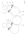
- Fig. 1 shows a schematic representation in side view of two printing units 1 of a printing press.
- the impression, rubber and plate cylinders 2, 3, 4 are shown. Between the two impression cylinders 2, a sheet guide cylinder 5 is arranged.
- the rubber cylinder 3 is designed as a coating forme cylinder 3.
- a sheet guiding device 6 is arranged, which is to be explained below using the sheet guiding device 6 in front of the printing nip 7.
- the sheet guiding device 6 after the printing nip 7 is arranged in mirror image or approximately mirror image to the sheet guiding device 6 in front of the printing nip 7.
- the sheet conveying direction 8 results from the direction of rotation of the cylinders 2.5, which is indicated by the arrow indicating the direction of rotation.
- Sheet guiding and impression cylinders 5.2 have the common tangent point t 2.5 .
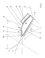
- the sheet guiding device 6 is designed as an air box 9 reaching over the sheet conveying path. It extends in the area above the tangent point t 2.5 from the sheet guiding cylinder 5 to near the printing gap 7 of the printing and blanket cylinders 2; 3.
- the air box 9 is pivotally mounted on the machine frame 15.
- the air box 9 is provided with a guide surface 11, which converges near the pressure gap 7 with a blocking surface 10 of the air box 9 adapted to the contour of the rubber cylinder 3 at the beginning of the air box 9, where an outlet opening 13 pointing in the direction of the pressure gap 7 in the air box 9 is introduced.
- the adaptation of the locking surface 10 to the contour of the rubber cylinder 3 is advantageous, but not a condition for the construction of a locking cushion.
- the guide surface 11 forms the guide gap 17 with the lateral surface of the printing cylinder 2. Seen in the direction of sheet conveyance, the guide gap 17 can converge or diverge or run parallel to the printing cylinder 2. However, it has proven to be advantageous if the air box 9 is pivoted in such a way that the guide gap 17 converges. (Sh.Fig.2).
- the blocking surface 10 is provided with at least one row of nozzles 14 (5 rows of nozzles in FIG. 2) available).
- the row of nozzles 14 extends across the width of the blocking surface 10 Blown air jet from the row of nozzles 14 is against the outer surface of the rubber cylinder 3 directed.
- the blocking surface 10 of the air box 9 is at a distance S from the outer surface of the blanket cylinder 3. It is essential for the number of row of nozzles 14 that an effective blocking cushion is built up to prevent uncontrolled air from flowing in and out. For the promising effect, it is not absolutely necessary that rows of nozzles are available. It is essential that a barrier cushion is built up, wherein the air can also be blown from individual nozzles arranged asymmetrically over the width of the barrier surface 10.
- the length L of the barrier surface 10 is essential for the construction of the barrier cushion. The larger the blocking area 10, the more effective the blocking pad that is built up. The length L of the blocking surface 10 is greater than the distance S.
- FIG. 3 shows a view in the direction B according to FIG. 2 onto the guide surface 11.
- the entire surface of the guide surface 11 is provided with nozzles 12 which blow vertically out of the guide surface 11.
- the nozzle density increases in the sheet conveying direction 8 (FIG. 3) or, according to another variant, in the sheet conveying direction and from outside to inside (FIG. 4).
- FIG. 5 shows a view of the air box 9 in the direction A according to another variant Fig. 2. It can be seen that the guide surface 11 from the outside (on both sides) to the inside has a converging distance from the surface of the printing cylinder 2. For simplification 5, the nozzles 12 in the guide plate are not shown.
- the sheet guide device 6 operates as follows:
- the air box 9 When conveying sheets, the air box 9 is pneumatically actuated by the fans 16.
- the air box 9 fulfills the function of a pressure accumulator.
- the one from the nozzles 12 emerging air forms an air cushion and thus acts on the one under the guide surface 11 guided sheet and forces it onto the impression cylinder 2.
- the sheet is from Spread out to the front and, if necessary, from the center outwards.
- the blocking pad prevents air from flowing in from the guide gap Direction of pressure gap 7, as well as the outflow of air from the area of the pressure gap 7th
- the sheet guiding device 6 can also be used if the printing unit 1 is used as a coating unit or is not involved in the printing. If it is not involved in printing, rubber and printing cylinders 2, 3 in the printing gap 7 are at a distance from one another.
- a barrier pad by a barrier surface 10 with rows of nozzles 14 that oppose a rubber cylinder 3 is directed is not to the application described (before Printing gap 7 limited by rubber and printing cylinders 2,3).
- the sheet guiding device 6 it is possible to arrange the sheet guiding device 6 to build up a blocking cushion after the printing nip 7 or to provide this in other places.
- the construction of a barrier cushion is everywhere useful where the sheet is supported by air and at or near the point of action inflowing air reduces the promising effect. In this case it is Building a barrier pad is useful as it has the effect of being blown directly on the bow Air increased.
- Fig. 6 and Fig. 7 show the sheet guide device for rigid substrates in detailed form.
- the sheet edge guide device 22 consists of an edge guide roller 19 rotatably mounted on a holder 18.
- the edge guide roller 19 is assigned above the holder 18 at an angle to the impression cylinder 2 and thus to the side edge of the sheet 21.
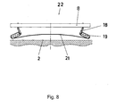
- the holder 18 is fixedly mounted on a guide 20 and can be displaced along this (see also FIG. 8).
- the edge guide roller 19 is the side edge of the sheet 21 assigned and the air box 9 is pivoted on the machine frame 15, that between the guide surface 11 and the periphery of the printing cylinder 2 is preferably a divergent gap arises.
- the rigid materials (sheets) 21 conveyed by the printing press first come into contact with the edge guide rollers 19 arranged on both sides in the rear area of the sheet guide device.
- the edge guide rollers 19 support the side edge of the sheet 21, so that the sheet rear edge is guided over the entire width at a distance below the guide surface 11.
- the sheet 21 After the sheet 21 has left the effective area of the edge guide rollers 19, it moves outwards as a result of its bending tension and lies against the guide surface 11 with the trailing edge.
- the rear edge of the sheet 21 has passed the end of the guide surface 11, the rear edge follows the common tangent between the impression cylinder 2 and the blanket cylinder 3.
- the air box 9 can be acted upon pneumatically when processing cardboard become.
- the air emerging from the nozzles 12 of the guide surface 11 acts on the arc 21 towards printing cylinder 2.
- the arrangement of the sheet guiding device and its function when processing limp materials (paper) is shown in FIG. 7.
- the edge guide roller 19 is placed outside the sheet format to be processed.
- the air box 9 is previously pneumatically actuated by the fans 16.
- the air box 9 was previously pivoted to the machine frame 15 such that a convergent gap is formed between the guide surface 11 and the periphery of the printing cylinder 2 in the sheet conveying direction 19. If the sheet 21 reaches the area of the guide surface 11, the air emerging from the nozzles 12 acts on the sheet 21 and forces it onto the printing cylinder 2.
- the sheet 21 is spread out and runs without creasing and without smearing in the printing nip 7 of printing and rubber cylinder 2.3. The sheet 21 does not come into contact with the guide surface 11.
Landscapes
- Supply, Installation And Extraction Of Printed Sheets Or Plates (AREA)
- Feeding Of Articles By Means Other Than Belts Or Rollers (AREA)
Abstract
Description
Nachteilig an diesen Einrichtungen ist weiterhin, dass aus dem Bereich des Druckspaltes der sich berührenden Zylinder Luft zwischen Bogenleiteinrichtung und Gummizylinder abfließen kann. Es können dadurch Luftströme auftreten, die das Bogenende des Bogens unterblasen können.
Auch ist nicht auszuschließen, dass vom Gummizylinder in den Druckspalt eingeschleppte Luft die glatte Auflage des Bedruckstoffes auf den Druckzylinder verhindert und damit einer störungsfreien Bogenführung hinderlich ist.
Eine derartige Bogenleiteinrichtung ist aus der DE-OS 21 56 577 bekannt. Gemäß dieser Druckschrift sind über einem Druckzylinder Führungswalzen in Reihe und achsparallel über die Breite des Zylinders angeordnet. Mittels der Führungswalzen soll das biegesteife Material in eine vorbestimmte Bahn gezwungen werden, um eine Berührung mit Maschinenteilen zu verhindern.
Nachteilig an dieser Bogenleiteinrichtung ist, dass eine derartige Anordnung der Rollen diese in Berührung mit dem bedruckten Bogen bringt. Dadurch kann es zu einem Abschmieren der Farbe kommen. Diese Einrichtung funktioniert nur, wenn im Druckmotiv durchgängig druckfreie Korridore vorhanden sind.
Nachteilig an dieser Einrichtung ist, dass sie für biegesteife Materialien eine gute Führungs- und Leitfunktion ausübt, für die Unterstützung der Bogenführung bei Verarbeitung von Papier jedoch nur bedingt geeignet ist.
Unter einer zunehmenden Düsendichte in der Führungsfläche wird verstanden, dass in Bogenförderrichtung bzw. nach einer zweiten Variante in und quer zur Bogenförderrichtung von außen nach innen der Anteil der Düsenfläche an der gesamten Führungsfläche zunimmt. Dies wird durch eine größere Anzahl von Düsen in der Führungsfläche und/oder durch größere Düsenöffnungen erreicht.
Die aus den Düsen der Führungsfläche im Bereich des Druckspaltes austretende Luft ist bestrebt, aus diesem Bereich auch über den Raum zwischen Gummizylinder und Luftkasten zu entweichen. Durch den Aufbau des Sperrpolsters wird diese Luft am Abfließen zwischen Gummizylinder und Luftkasten gehindert. Die Luft fließt dadurch zwischen Führungsfläche und Bogen entgegen der Bogenförderrichtung ab und streicht damit den Bogen auf dem Druckzylinder aus. Gleichzeitig fließt eine Luftströmung aus dem unter hohem Druck stehenden Sperrpolster in den Bereich vor den Druckspalt ab, erhöht den Luftdruck vor dem Druckspalt, wird in diesem Bereich umgelenkt und fließt am Bogen entgegen der Bogenlaufrichtung durch den Führungsspalt mit ab und erhöht dabei die vorstehende beschriebene Wirkung. Dadurch wird verhindert, dass in diesem Bereich der Bogen im hinteren Bereich unterblasen wird.
Die Bogenkantenleiteinrichtung wird dagegen nur bei Verarbeitung von biegesteifen Materialien wirksam. Die Kantenleitrollen befinden sich sonst außerhalb des Formatbereiches.
Nachdem der Bogen die Kantenleitrolle passiert hat, wird er an die Bogenleiteinrichtung übergeben. Die Bogenführung durch die Führungsfläche des Luftkastens erfolgt durch Entlanggleiten der Bogenhinterkante an der Führungsfläche, wobei ein Abschmieren des Bogens vermieden wird, da der Bogen die Führungsfläche nur mit seiner Hinterkante berührt.
Durch die Kombination der Bogenkantenleiteinrichtung mit der Bogenleiteinrichtung wird sichergestellt, dass alle biegesteifen Materialien ohne abzuschmieren und Beschädigungen vor der Kontaktzone gefördert und bedruckt werden können. Die Bogenleiteinrichtung ist einfach im Aufbau und sie ist mit wenigen Handgriffen bei Auftragswechsel auf die Verarbeitung von Bogen einer anderen Materialdicke einstellbar.
In den dazugehörenden Zeichnungen zeigt
- Fig. 1:
- Ausschnitt aus einer Druckmaschine
- Fig. 2:
- Bogenleiteinrichtung in detaillierter Darstellung
- Fig. 3:
- Blick auf die Führungsfläche mit der Düsenanordnung (erste Variante; Blick B nach Fig.2)
- Fig. 4:
- Blick auf die Führungsfläche mit der Düsenanordnung(zweite Variante; Blick B nach Fig.2)
- Fig. 5:
- Blick auf den Luftkasten nach einer Variante der Gestaltung der Führungsfläche in Bogenförderrichtung (Blickrichtung A gemäß Fig. 2)
- Fig. 6:
- Bogenleiteinrichtung bei Verarbeitung von biegesteifen Materialien (Karton)
- Fig. 7:
- Bogenleiteinrichtung bei Verarbeitung von biegeschlaffen Materialien (Papier)
- Fig. 8:
- Blick auf die Kantenleiteinrichtung in Blickrichtung A gem. Fig. 6
Vor und nach dem Druckspalt 7 von Gummi- und Druckzylinder 3,2 ist eine Bogenleiteinrichtung 6 angeordnet, die nachfolgend anhand der Bogenleiteinrichtung 6 vor dem Druckspalt 7 erklärt werden soll. Die Bogenleiteinrichtung 6 nach dem Druckspalt 7 ist spiegelbildlich bzw. annähernd spiegelbildlich zur Bogenleiteinrichtung 6 vor dem Druckspalt 7 angeordnet. Die Bogenförderrichtung 8 ergibt sich aus der Drehrichtung der Zylinder 2,5, die durch den Drehrichtungspfeil angezeigt ist.
Bogenführungs- und Druckzylinder 5,2 haben den gemeinsamen Tangentenpunkt t2,5.
Der Luftkasten 9 ist schwenkbar am Maschinengestell 15 gelagert. Zum Luftkasten 9 führen pneumatische Luftversorgungssysteme 16, die im Ausführungsbeispiel als Ventilatoren 16 ausgebildet sind.
In Richtung Bogen ist der Luftkasten 9 mit einer Führungsfläche 11 versehen, die nahe des Druckspaltes 7 mit einer der Kontur des Gummizylinders 3 angepassten Sperrfläche 10 des Luftkastens 9 am Anfang des Luftkastens 9 zusammenläuft, wo im Luftkasten 9 eine in Richtung Druckspalt 7 weisende Austrittsöffnung 13 eingebracht ist. Die Anpassung der Sperrfläche 10 an die Kontur des Gummizylinders 3 ist vorteilhaft, jedoch nicht Bedingung für den Aufbau eines Sperrpolsters.
Die Führungsfläche 11 bildet mit der Mantelfläche des Druckzylinders 2 den Führungsspalt 17. In Bogenförderrichtung gesehen, kann der Führungsspalt 17 zum Druckzylinder 2 konvergieren oder divergieren oder parallel verlaufen. Als vorteilhaft hat sich jedoch erwiesen, wenn der Luftkasten 9 derart geschwenkt wird, dass der Führungsspalt 17 konvergiert. (sh.Fig.2).
Wesentlich für die Anzahl der Düsenreihe 14 ist, dass ein wirkungsvolles Sperrpolster gegen das Ab- und Zufließen unkontrollierter Luft aufgebaut wird. Für die erfolgversprechende Wirkung ist es aber nicht unbedingt erforderlich, dass Düsenreihen vorhanden sind. Wesentlich ist, dass ein Sperrpolster aufgebaut wird, wobei die Luft auch aus über die Breite der Sperrfläche 10 asymmetrisch angeordneten Einzeldüsen geblasen werden kann. Die Länge L der Sperrfläche 10 ist wesentlich für den Aufbau des Sperrpolsters. Je größer die Sperrfläche 10 ist, um so wirkungsvoller ist das aufgebaute Sperrpolster. Dabei ist die Länge L der Sperrfläche 10 größer als der Abstand S.
Die Führungsfläche 11 ist ganzflächig mit Düsen 12 versehen, die senkrecht aus der Führungsfläche 11 blasen. Dabei nimmt die Düsendichte in Bogenförderrichtung 8 (Fig. 3) bzw. nach einer anderen Variante in Bogenförderrichtung und von außen nach innen zu (Fig. 4).
Im Einzelnen besteht die Bogenkantenleiteinrichtung 22 aus einer drehbar an einem Halter 18 gelagerten Kantenleitrolle 19.
Die Kantenleitrolle 19 ist über dem Halter 18 unter einem Winkel dem Druckzylinder 2 und damit der Seitenkante des Bogens 21 zugeordnet. Der Halter 18 ist auf einer Führung 20 fest gelagert und längs dieser verschiebbar (s. auch Fig. 8).
Nachdem der Bogen 21 den Wirkbereich der Kantenleitrollen 19 verlassen hat, bewegt er sich infolge seiner Biegespannung nach außen und legt sich mit der Hinterkante an die Führungsfläche 11 an. Nachdem die Hinterkante des Bogens 21 das Ende der Führungsfläche 11 passiert hat, folgt die Hinterkante der gemeinsamen Tangente zwischen Druckzylinder 2 und Gummizylinder 3.
Die Kantenleitrolle 19 wird außerhalb des zu verarbeitenden Bogenformates gestellt. Der Luftkasten 9 wird zuvor durch die Ventilatoren 16 pneumatisch beaufschlagt. Der Luftkasten 9 wurde zuvor derart zum Maschinengestell 15 geschwenkt, dass zwischen Führungsfläche 11 und der Peripherie des Druckzylinders 2 in Bogenförderrichtung 19 ein konvergenter Spalt entsteht.
Gelangt der Bogen 21 in den Bereich der Führungsfläche 11, wirkt die aus den Düsen 12 austretende Luft auf den Bogen 21 und zwingt diesen auf den Druckzylinder 2. Der Bogen 21 wird dabei ausgestrichen und läuft knitterfrei und ohne abzuschmieren in den Druckspalt 7 von Druck- und Gummizylinder 2,3 ein. Eine Berührung des Bogens 21 mit der Führungsfläche 11 findet nicht statt.
- 1
- Druckwerk
- 2
- Druckzylinder
- 3
- Gummizylinder; Lackformzylinder
- 4
- Plattenzylinder
- 5
- Bogenführungszylinder
- 6
- Bogenleiteinrichtung
- 7
- Druckspalt
- 8
- Bogenförderrichtung
- 9
- Luftkasten
- 10
- Sperrfläche
- 11
- Führungsfläche
- 12
- Düsen
- 13
- Austrittsöffnung
- 14
- Düsenreihe
- 15
- Maschinengestell
- 16
- Luftversorgungssystem, Ventilator
- 17
- Führungsspalt
- 18
- Halter
- 19
- Kantenleitrolle
- 20
- Führung
- 21
- Bogen
- 22
- Bogenkantenleiteinrichtung
- t2,5
- Tangentenpunkt von Druck- und Bogenführungszylinder
- S
- Abstand zwischen Sperrfläche und Gummizylinder
- L
- Länge der Sperrfläche
Claims (20)
- Bogenleiteinrichtung in Druckmaschinen zur Unterstützung der Bogenführung im Bereich des Druckspaltes (7) zweier Zylinder (2, 3), bestehend aus einem sich über die Breite des Bogenförderweges erstreckenden, mit einem Luftversorgungssystem (16) verbundenen Luftkasten (9), wobei der Luftkasten (9) eine zum Bogenförderweg weisende Führungsfläche (11) mit Düsen (12) aufweist und die Dichte der Düsen (12) in der Führungsfläche (11) in Bogenförderrichtung (8) zunimmt.
- Bogenleiteinrichtung in Druckmaschinen zur Unterstützung der Bogenführung im Bereich des Druckspaltes (7) zweier Zylinder (2, 3), bestehend aus einem sich über die Breite des Bogenförderweges erstreckenden, mit einem Luftversorgungssystem (16) verbundenen Luftkasten (9), wobei der Luftkasten (9) eine zum Bogenförderweg weisende Führungsfläche (11) mit Düsen (12) aufweist und die Dichte der Düsen (12) in der Führungsfläche (11) in Bogenförderrichtung (8) und von außen nach innen zunimmt.
- Bogenleiteinrichtung nach Anspruch 1, wobei der Luftkasten (9) sich von dem dem Druckzylinder (2) vorgeordneten Bogenführungszylinder (5) bis nahe zum Druckspalt (7) erstreckt.
- Bogenleiteinrichtung nach Anspruch 1 oder 2, wobei die Düsen (12) in der gesamten Führungsfläche (11) angeordnet sind.
- Bogenleiteinrichtung nach Anspruch 1 oder 2, wobei die Strömung im Führungsspalt (17) entgegen der Bogenförderrichtung (8) und von innen nach außen verläuft.
- Bogenleiteinrichtung nach Anspruch 1 oder 2, wobei die Führungsfläche (11) axial zur Bogenförderrichtung (8) von außen nach innen zur Druckzylinderoberfläche konvergiert.
- Bogenleiteinrichtung nach Anspruch 1 oder 2, wobei in Bogenförderrichtung die Führungsfläche (11) mit der Mantelfläche des Druckzylinders (2) einen konvergierenden oder einen divergierenden oder einen parallelen Spalt (17) bildet.
- Bogenleiteinrichtung nach Anspruch 1, 2 oder 4, wobei die Düsen (12) senkrecht aus der Führungsfläche (11) austreten.
- Bogenleiteinrichtung in Druckmaschinen zur Unterstützung der Bogenförderung im Bereich des Druckspaltes (7) zweier Zylinder (2,3), bestehend aus einem sich über die Breite des Bogenförderweges erstreckenden, mit einem Luftversorgungssystem (16) verbundenen Luftkasten (9), wobei der Luftkasten (9) eine auf den Bogenförderweg gerichtete Führungsfläche (11) mit Düsen (12) aufweist, die Führungsfläche (11) zur Mantelfläche des Druckzylinders (2) einen Abstand besitzt und der Luftkasten (9) eine zum Gummizylinder (3) gerichtete beabstandete Sperrfläche (10) mit Düsenreihen (14) aufweist.
- Bogenleiteinrichtung nach Anspruch 9, wobei die Sperrfläche (10) des Luftkastens (9) der Kontur des Gummizylinders (3) angepasst ist.
- Bogenleiteinrichtung nach Anspruch 9, wobei die aus den Düsenreihen (14) austretende Luft zwischen der Sperrfläche (10) und dem Gummizylinder (3) ein Sperrpolster erzeugt.
- Bogenleiteinrichtung nach Anspruch 9, wobei die Sperrfläche (10) im Abstand (S) zum Gummizylinder (3) angeordnet ist.
- Bogenleiteinrichtung nach Anspruch 9 und 12, wobei die Länge (L) der Sperrfläche (10) wesentlich für die Wirkung des Luftpolsters ist.
- Bogenleiteinrichtung nach Anspruch 12 und 13, wobei die Länge L der Sperrfläche (10) größer ist als der Abstand S des Luftkastens (9) zur Mantelfläche des Gummizylinders (3).
- Bogenleiteinrichtung nach Anspruch 9, wobei die Bogenleiteinrichtung vor und nach dem Druckspalt (7) angeordnet ist.
- Bogenleiteinrichtung in Druckmaschinen zur Unterstützung der Bogenführung vor dem Druckspalt (7) zwischen Druck- und Gummizylinder (2,3) oberhalb des Tangentenpunktes t2,5 von Druckzylinder (2) und dem dem Druckzylinder (2) vorgeordneten Bogenführungszylinder (5), bestehend aus der Kombination einerwahlweise zuschaltbaren Bogenkantenleiteinrichtung (22) mit auf die Seitenkante des Bogens (21) einstellbaren Kantenleitrollen (19) undeiner der Bogenkantenleiteinrichtung (22) zugeordneten Bogenleiteinrichtung (6), wobei die Bogenleiteinrichtung (6)über die Breite des Bogenförderweges (19) angeordnet ist,einen pneumatisch beaufschlagbaren Luftkasten (9) aufweist undder Luftkasten (9) mit einer auf den Bogenförderweg (19) gerichteten mit Düsen (12) versehenen Führungsfläche (11) ausgestattet ist.
- Bogenleiteinrichtung nach Anspruch 16, wobei die Bogenkantenleiteinrichtung (22) bei der Verarbeitung biegesteifer Materialien wirksam wird.
- Bogenleiteinrichtung nach Anspruch 16, wobei der Luftkasten (9) am Maschinengestell (15) schwenkbar angeordnet ist.
- Bogenleiteinrichtung nach Anspruch 16, wobei die Führungsfläche (11) des Luftkastens (9) bei Verarbeitung von biegesteifen Materialien (Karton) in Bogenlaufrichtung (19) mit dem Druckzylinder (2) einen vorzugsweise divergenten Spalt bildet.
- Bogenleiteinrichtung nach Anspruch 16, wobei die Führungsfläche (11) des Luftkastens (9) bei Verarbeitung von biegeschlaffen Materialien (Papier) in Bogenlaufrichtung (19) mit dem Druckzylinder (2) einen konvergenten Spalt bildet.
Priority Applications (1)
| Application Number | Priority Date | Filing Date | Title |
|---|---|---|---|
| EP08164150A EP1995064B1 (de) | 2000-10-26 | 2001-10-23 | Bogenglätteinrichtung in Druckmaschinen zur Unterstützung der Bogenführung |
Applications Claiming Priority (6)
| Application Number | Priority Date | Filing Date | Title |
|---|---|---|---|
| DE10053106 | 2000-10-26 | ||
| DE10053105 | 2000-10-26 | ||
| DE2000153105 DE10053105A1 (de) | 2000-10-26 | 2000-10-26 | Leiteinrichtung in Druckmaschinen |
| DE2000153104 DE10053104A1 (de) | 2000-10-26 | 2000-10-26 | Bogenglätteinrichtung in Druckmaschinen zur Unterstützung der Bogenführung |
| DE2000153106 DE10053106A1 (de) | 2000-10-26 | 2000-10-26 | Bogenglätteinrichtung in Druckmaschinen zur Unterstützung der Bogenführung |
| DE10053104 | 2000-10-26 |
Related Child Applications (2)
| Application Number | Title | Priority Date | Filing Date |
|---|---|---|---|
| EP08164150A Division EP1995064B1 (de) | 2000-10-26 | 2001-10-23 | Bogenglätteinrichtung in Druckmaschinen zur Unterstützung der Bogenführung |
| EP08164150.8 Division-Into | 2008-09-11 |
Publications (3)
| Publication Number | Publication Date |
|---|---|
| EP1201428A2 true EP1201428A2 (de) | 2002-05-02 |
| EP1201428A3 EP1201428A3 (de) | 2007-04-18 |
| EP1201428B1 EP1201428B1 (de) | 2011-03-23 |
Family
ID=27214131
Family Applications (2)
| Application Number | Title | Priority Date | Filing Date |
|---|---|---|---|
| EP08164150A Expired - Lifetime EP1995064B1 (de) | 2000-10-26 | 2001-10-23 | Bogenglätteinrichtung in Druckmaschinen zur Unterstützung der Bogenführung |
| EP20010125107 Expired - Lifetime EP1201428B1 (de) | 2000-10-26 | 2001-10-23 | Bogenleiteinrichtung in Druckmaschinen zur Unterstützung der Bogenführung |
Family Applications Before (1)
| Application Number | Title | Priority Date | Filing Date |
|---|---|---|---|
| EP08164150A Expired - Lifetime EP1995064B1 (de) | 2000-10-26 | 2001-10-23 | Bogenglätteinrichtung in Druckmaschinen zur Unterstützung der Bogenführung |
Country Status (2)
| Country | Link |
|---|---|
| EP (2) | EP1995064B1 (de) |
| DE (1) | DE50115825D1 (de) |
Cited By (3)
| Publication number | Priority date | Publication date | Assignee | Title |
|---|---|---|---|---|
| DE102013209699A1 (de) | 2012-05-24 | 2013-11-28 | Koenig & Bauer Aktiengesellschaft | Bogenführungseinrichtung für eine bogenverarbeitende Maschine und Verfahren zum Glattstreichen eines Bogens auf einem Zylinder |
| CN108537949A (zh) * | 2018-04-15 | 2018-09-14 | 浙江师范大学 | 全自动双面展平纸币整理机 |
| CN111098592A (zh) * | 2018-10-29 | 2020-05-05 | 海德堡印刷机械股份公司 | 在压印间隙之前具有喷吹装置的印刷机 |
Family Cites Families (10)
| Publication number | Priority date | Publication date | Assignee | Title |
|---|---|---|---|---|
| DE2156577B2 (de) * | 1971-11-15 | 1974-07-04 | Roland Offsetmaschinenfabrik Faber & Schleicher Ag, 6050 Offenbach | Vorgreiferschwinganlage |
| DE2603483B2 (de) * | 1976-01-30 | 1978-06-08 | Reinhard Mohn Ohg, 4830 Guetersloh | Verfahren zum Führen eines Bogens zum gleichzeitigen Bedrucken mit einem Schön- und Widerdruck sowie Vorrichtung zur Durchführung des Verfahrens |
| GB2190364A (en) * | 1986-05-14 | 1987-11-18 | Wallace Knight Ltd | An assembly for preventing the detachment of a substrate from a revolving cylinder |
| WO1993003990A1 (de) * | 1991-08-16 | 1993-03-04 | Heidelberger Druckmaschinen Ag | Einrichtung zur regelung und/oder steuerung einzelner stellelemente im auslegerbereich einer druckmaschine |
| DE9115032U1 (de) * | 1991-12-04 | 1992-01-16 | Heidelberger Druckmaschinen Ag, 6900 Heidelberg | Bogenausleger an Druckmaschinen |
| DE4443493C2 (de) * | 1994-12-07 | 2002-06-06 | Koenig & Bauer Ag | Leiteinrichtung für biegesteife Materialien |
| DE19549845B4 (de) * | 1995-06-24 | 2007-07-12 | Heidelberger Druckmaschinen Ag | Vorrichtung zur Erzielung einer einwandfreien Auflage eines Bedruckstoffes in einer Druckmaschine |
| DE19723146C2 (de) * | 1997-06-03 | 1999-11-18 | Koenig & Bauer Ag | Bogenweiche zur Unterstützung der Bogenführung |
| DE19753089C2 (de) * | 1997-11-29 | 2000-06-29 | Roland Man Druckmasch | Bogenführungseinrichtung in einer Druckmaschine |
| DE29721185U1 (de) * | 1997-11-29 | 1998-01-15 | MAN Roland Druckmaschinen AG, 63075 Offenbach | Bogenführungseinrichtung in einer Druckmaschine |
-
2001
- 2001-10-23 DE DE50115825T patent/DE50115825D1/de not_active Expired - Lifetime
- 2001-10-23 EP EP08164150A patent/EP1995064B1/de not_active Expired - Lifetime
- 2001-10-23 EP EP20010125107 patent/EP1201428B1/de not_active Expired - Lifetime
Cited By (5)
| Publication number | Priority date | Publication date | Assignee | Title |
|---|---|---|---|---|
| DE102013209699A1 (de) | 2012-05-24 | 2013-11-28 | Koenig & Bauer Aktiengesellschaft | Bogenführungseinrichtung für eine bogenverarbeitende Maschine und Verfahren zum Glattstreichen eines Bogens auf einem Zylinder |
| DE102013209699B4 (de) * | 2012-05-24 | 2020-08-27 | Koenig & Bauer Ag | Bogenführungseinrichtung für eine bogenverarbeitende Maschine |
| CN108537949A (zh) * | 2018-04-15 | 2018-09-14 | 浙江师范大学 | 全自动双面展平纸币整理机 |
| CN111098592A (zh) * | 2018-10-29 | 2020-05-05 | 海德堡印刷机械股份公司 | 在压印间隙之前具有喷吹装置的印刷机 |
| CN111098592B (zh) * | 2018-10-29 | 2024-01-30 | 海德堡印刷机械股份公司 | 在压印间隙之前具有喷吹装置的印刷机 |
Also Published As
| Publication number | Publication date |
|---|---|
| EP1995064A1 (de) | 2008-11-26 |
| EP1995064B1 (de) | 2012-12-12 |
| EP1201428B1 (de) | 2011-03-23 |
| EP1201428A3 (de) | 2007-04-18 |
| DE50115825D1 (de) | 2011-05-05 |
Similar Documents
| Publication | Publication Date | Title |
|---|---|---|
| EP0706881B1 (de) | Bogenführungsmodul für eine Wendeeinrichtung in einer für Schön- und Widerdruck einsetzbaren Rotations-druckmaschine | |
| DE4217813A1 (de) | Vorrichtung zum Erzielen einer flächigen Anlage von Bedruckstoffen | |
| EP0858889B1 (de) | Bogenrotationsdruckmaschine mit einem Entstaubungssystem mit Bogenführungseinrichtung | |
| EP0922574B1 (de) | Bogenführungseinrichtung in einer Druckmaschine | |
| DE4443493A1 (de) | Leiteinrichtung für biegesteife Materialien | |
| EP0922577B1 (de) | Bogenführungseinrichtung in einer Druckmaschine | |
| EP0000011B2 (de) | Bogenrotationsdruckmaschine. | |
| AT413274B (de) | Bogenleiteinrichtung in einer rotationsdruckmaschine | |
| DE19829095A1 (de) | Bogenführungseinrichtung in einer Druckmaschine | |
| EP0924069B1 (de) | Bogenführungseinrichtung in einer Druckmaschine | |
| DE10056018B4 (de) | Einrichtung zur Unterstützung der Bogenführung und Bogenablage | |
| DE19814006C1 (de) | Verfahren und Einrichtung zur Bogenführung an einer Leitrakel in Druckmaschinen | |
| EP2011650A2 (de) | Bogenführung für Bogeninspektionssystem | |
| DE4430105C2 (de) | Verfahren und Vorrichtung zur flächigen Führung von im Greiferschluß fixierten Bogen auf einer gekrümmten Oberfläche eines Zylinders einer Roationsdruckmaschine | |
| EP1995064B1 (de) | Bogenglätteinrichtung in Druckmaschinen zur Unterstützung der Bogenführung | |
| DE4342203C2 (de) | Einrichtung zum Einwirken auf Bogen in einer Bogenrotationsdruckmaschine | |
| DE4344039A1 (de) | Bogenleiteinrichtung in umstellbaren Druckmaschinen | |
| EP0662439A1 (de) | Pneumatische Bogenleiteinrichtung | |
| EP0922575B1 (de) | Bogenführungseinrichtung in einer Druckmaschine | |
| DE20313394U1 (de) | Auslegevorrichtung für eine Bogenverarbeitungsmaschine | |
| DD253020A1 (de) | Leiteinrichtung in auslegern von bogendruckmaschinen | |
| DE3509696A1 (de) | Einrichtung in bogenauslegern | |
| DE10023435A1 (de) | Leiteinrichtung in umstellbaren Druckmaschinen | |
| DD225411A1 (de) | Einrichtung zur einwirkung auf den bogen in bogenauslegern | |
| DE102010042928B4 (de) | Bogentransportvorrichtung in einer Verarbeitungsmaschine und Verfahren zum Führen von Bogenmaterial |
Legal Events
| Date | Code | Title | Description |
|---|---|---|---|
| PUAI | Public reference made under article 153(3) epc to a published international application that has entered the european phase |
Free format text: ORIGINAL CODE: 0009012 |
|
| AK | Designated contracting states |
Kind code of ref document: A2 Designated state(s): AT BE CH CY DE DK ES FI FR GB GR IE IT LI LU MC NL PT SE TR |
|
| AX | Request for extension of the european patent |
Free format text: AL;LT;LV;MK;RO;SI |
|
| RIN1 | Information on inventor provided before grant (corrected) |
Inventor name: WEISBACH, GUENTER Inventor name: BEYER, MICHAEL Inventor name: KOCH, MICHAEL Inventor name: REINECKER, MATTHIAS Inventor name: LEUSCHKE, ANDREAS |
|
| PUAL | Search report despatched |
Free format text: ORIGINAL CODE: 0009013 |
|
| AK | Designated contracting states |
Kind code of ref document: A3 Designated state(s): AT BE CH CY DE DK ES FI FR GB GR IE IT LI LU MC NL PT SE TR |
|
| AX | Request for extension of the european patent |
Extension state: AL LT LV MK RO SI |
|
| RIC1 | Information provided on ipc code assigned before grant |
Ipc: B41F 21/00 20060101AFI20020222BHEP Ipc: B65H 5/36 20060101ALI20070313BHEP |
|
| 17P | Request for examination filed |
Effective date: 20070609 |
|
| 17Q | First examination report despatched |
Effective date: 20071017 |
|
| AKX | Designation fees paid |
Designated state(s): DE FR GB |
|
| GRAP | Despatch of communication of intention to grant a patent |
Free format text: ORIGINAL CODE: EPIDOSNIGR1 |
|
| GRAS | Grant fee paid |
Free format text: ORIGINAL CODE: EPIDOSNIGR3 |
|
| GRAA | (expected) grant |
Free format text: ORIGINAL CODE: 0009210 |
|
| AK | Designated contracting states |
Kind code of ref document: B1 Designated state(s): DE FR GB |
|
| REG | Reference to a national code |
Ref country code: GB Ref legal event code: FG4D Free format text: NOT ENGLISH |
|
| REF | Corresponds to: |
Ref document number: 50115825 Country of ref document: DE Date of ref document: 20110505 Kind code of ref document: P |
|
| REG | Reference to a national code |
Ref country code: DE Ref legal event code: R096 Ref document number: 50115825 Country of ref document: DE Effective date: 20110505 |
|
| PLBE | No opposition filed within time limit |
Free format text: ORIGINAL CODE: 0009261 |
|
| STAA | Information on the status of an ep patent application or granted ep patent |
Free format text: STATUS: NO OPPOSITION FILED WITHIN TIME LIMIT |
|
| 26N | No opposition filed |
Effective date: 20111227 |
|
| REG | Reference to a national code |
Ref country code: DE Ref legal event code: R097 Ref document number: 50115825 Country of ref document: DE Effective date: 20111227 |
|
| PGFP | Annual fee paid to national office [announced via postgrant information from national office to epo] |
Ref country code: DE Payment date: 20121103 Year of fee payment: 12 Ref country code: FR Payment date: 20121031 Year of fee payment: 12 |
|
| PGFP | Annual fee paid to national office [announced via postgrant information from national office to epo] |
Ref country code: GB Payment date: 20121019 Year of fee payment: 12 |
|
| GBPC | Gb: european patent ceased through non-payment of renewal fee |
Effective date: 20131023 |
|
| REG | Reference to a national code |
Ref country code: DE Ref legal event code: R119 Ref document number: 50115825 Country of ref document: DE Effective date: 20140501 |
|
| PG25 | Lapsed in a contracting state [announced via postgrant information from national office to epo] |
Ref country code: GB Free format text: LAPSE BECAUSE OF NON-PAYMENT OF DUE FEES Effective date: 20131023 |
|
| REG | Reference to a national code |
Ref country code: FR Ref legal event code: ST Effective date: 20140630 |
|
| PG25 | Lapsed in a contracting state [announced via postgrant information from national office to epo] |
Ref country code: DE Free format text: LAPSE BECAUSE OF NON-PAYMENT OF DUE FEES Effective date: 20140501 Ref country code: FR Free format text: LAPSE BECAUSE OF NON-PAYMENT OF DUE FEES Effective date: 20131031 |