EP1201445A2 - Dispositif d'enregistrement - Google Patents
Dispositif d'enregistrement Download PDFInfo
- Publication number
- EP1201445A2 EP1201445A2 EP01125866A EP01125866A EP1201445A2 EP 1201445 A2 EP1201445 A2 EP 1201445A2 EP 01125866 A EP01125866 A EP 01125866A EP 01125866 A EP01125866 A EP 01125866A EP 1201445 A2 EP1201445 A2 EP 1201445A2
- Authority
- EP
- European Patent Office
- Prior art keywords
- conveying
- motor
- recording
- recording medium
- conveying roller
- Prior art date
- Legal status (The legal status is an assumption and is not a legal conclusion. Google has not performed a legal analysis and makes no representation as to the accuracy of the status listed.)
- Granted
Links
- 230000005540 biological transmission Effects 0.000 claims description 17
- 238000010586 diagram Methods 0.000 description 8
- 238000000034 method Methods 0.000 description 5
- 230000000694 effects Effects 0.000 description 3
- 238000007796 conventional method Methods 0.000 description 2
- 239000006185 dispersion Substances 0.000 description 2
- 239000010408 film Substances 0.000 description 2
- 239000007788 liquid Substances 0.000 description 2
- 230000004048 modification Effects 0.000 description 2
- 238000012986 modification Methods 0.000 description 2
- 238000009835 boiling Methods 0.000 description 1
- 230000003247 decreasing effect Effects 0.000 description 1
- 230000005415 magnetization Effects 0.000 description 1
- 238000004519 manufacturing process Methods 0.000 description 1
- 230000002093 peripheral effect Effects 0.000 description 1
- 230000001360 synchronised effect Effects 0.000 description 1
- 239000010409 thin film Substances 0.000 description 1
Images


Classifications
-
- B—PERFORMING OPERATIONS; TRANSPORTING
- B41—PRINTING; LINING MACHINES; TYPEWRITERS; STAMPS
- B41J—TYPEWRITERS; SELECTIVE PRINTING MECHANISMS, i.e. MECHANISMS PRINTING OTHERWISE THAN FROM A FORME; CORRECTION OF TYPOGRAPHICAL ERRORS
- B41J11/00—Devices or arrangements of selective printing mechanisms, e.g. ink-jet printers or thermal printers, for supporting or handling copy material in sheet or web form
- B41J11/36—Blanking or long feeds; Feeding to a particular line, e.g. by rotation of platen or feed roller
- B41J11/42—Controlling printing material conveyance for accurate alignment of the printing material with the printhead; Print registering
-
- B—PERFORMING OPERATIONS; TRANSPORTING
- B41—PRINTING; LINING MACHINES; TYPEWRITERS; STAMPS
- B41J—TYPEWRITERS; SELECTIVE PRINTING MECHANISMS, i.e. MECHANISMS PRINTING OTHERWISE THAN FROM A FORME; CORRECTION OF TYPOGRAPHICAL ERRORS
- B41J13/00—Devices or arrangements of selective printing mechanisms, e.g. ink-jet printers or thermal printers, specially adapted for supporting or handling copy material in short lengths, e.g. sheets
- B41J13/0009—Devices or arrangements of selective printing mechanisms, e.g. ink-jet printers or thermal printers, specially adapted for supporting or handling copy material in short lengths, e.g. sheets control of the transport of the copy material
Definitions
- the present invention relates to a recording apparatus which forms an image on a recording medium such as a sheet or the like.
- a method of stopping the DC motor basically, a method of turning off a power supply of the motor when the rotation of a roller to convey the sheet reaches a target position and thus stopping the motor by inertia is general.
- a first manner there is a manner to increase a quantity of information in the low-speed driving immediately before the motor stops and thus improve controllability by using an analog encoder so as to increase resolution of the rotary encoder.
- a second manner there is a manner to sufficiently enlarge the diameter of the rotary encoder (codewheel) as compared with that of the conveying roller to prevent accuracy decrease by an eccentric of the encoder, and also to increase a peripheral speed of an encoder slit to increase the number of counts of the encoder slit during the low-speed driving immediately before the motor stops, so as to increase the quantity of information and thus improve the controllability.
- the disturbance torque can be eliminated and controlled by lowering to a certain extent the driving speed immediately before the motor stops.
- servo control is executed until the last time that the motor stops by increasing the quantity of information during the low-speed driving immediately before the motor stops so as to suppress small-period torque change and speed change, and also the accuracy is secured by reducing eccentric errors of the conveying roller and the encoder as much as possible so as to tolerate to a certain extent dispersion of the stop accuracy caused by the control.
- the analog encoder and the large-diameter codewheel are adopted, thereby increasing cost.
- the torque (or speed) is forcibly suppressed immediately before the motor stops.
- the stop accuracy tends to be influenced and the stop control becomes complicated, because of dispersion caused by mass production regarding the cogging torque ripple of the motor.
- control of a pitch in the torque change and the speed change smaller than the period of the cogging torque ripple of the motor, such as an interlock change of a gear and a belt acting as driving transmission means, is more difficult, whereby such an inconvenience can not be solved by the conventional method.
- An object of the present invention is to provide a recording apparatus equipped with a conveying configuration in which stop accuracy of a recording medium is not influenced by a torque (speed) ripple of a conveying motor or a transmission means and which is highly accurate and low cost.
- Another object of the present invention is to provide a recording apparatus which comprises a conveying roller for conveying a recording medium, a conveying motor for generating driving force to drive the conveying roller, a driving transmission means for transmitting the driving force of the conveying motor to the conveying roller, a detecting means for detecting a rotation angle of the conveying roller, and a control means for controlling driving and stopping of the conveying roller on the basis of a signal from the detecting means, wherein a conveying quantity of the recording medium at a time of recording operation is an integer multiple of a conveying quantity of the recording medium corresponding to one period of a torque change or a speed change caused by the conveying motor or the driving transmission means.
- serial printer equipped with an inkjet head having a detachable ink tank will be explained by way of example.
- the present invention is not limited to this but applicable to a so-called line printer having a long recording head not executing a scan in a row direction.
- Fig. 1 is an outside perspective diagram of the serial inkjet printer being an example of a recording apparatus to which the present invention is applied.
- a guide shaft 103 slidably guiding a carriage 102 in a main scan direction is fixed to a chassis 114 of the printer.
- a cartridge-type recording head 101 detachably having the ink tank is exchangeably mounted on the carriage 102.
- a belt 104 acting as a driving transmission means is engaged to the part of the carriage 102, and put (or wound) on a pulley and a rotation axis of a carriage motor 105 acting as a driving means, along the guide shaft 103.
- the carriage motor 105 By driving the carriage motor 105, the carriage 102 equipped with the recording head 101 can be shifted in the main scan direction.
- a recording sheet (recording medium) 115 fed from a sheet feed base 106 is conveyed toward a direction intersecting the main scan direction (preferably a direction perpendicular to the main scan direction) by a conveying roller 110, and recording is then executed on a platen 112 by the recording head 101.
- the conveying roller 110 is rotatably attached to the chassis 114.
- a pinch roller 111 rotating pursuant to the conveying roller 110 is arranged on the conveying roller 110 in the state that the roller 111 is being pressurized by a pinch roller spring (not shown).
- a conveying roller gear 109 is attached to the end of the axis of the conveying roller 110.
- a motor gear 108 attached to the rotation axis of a conveying motor 107 acting as a DC motor is engaged with the conveying roller gear 109.
- a codewheel 116 is fitted into the axis of the conveying roller 110, and an encoder sensor 117 is disposed on the periphery of the codewheel 116.
- a configuration that a droplet is emitted from a nozzle by using film boiling caused by thermal energy is applied to liquid is applicable, and also another configuration that a thin film element is minutely displaced according to an electrical signal input thereto to cause a nozzle to emit liquid is applicable.
- the recording sheets 115 are being stacked on the sheet feed base 106 while such the printer is on standby for recording, and the sheet 115 is fed inside the apparatus by a not-shown sheet feed roller when the recording starts.
- the conveying roller 110 is rotated by driving force of the conveying motor 107 acting as the DC motor through a train of gears (the motor gear 108, the conveying roller gear 109) acting as the driving transmission means, to convey the fed recording sheet 115.
- the recording sheet 115 is conveyed by an appropriate conveying quantity by the conveying roller 110 and the following pinch roller 111, and the conveying quantity is controlled by detecting and counting a slit (not shown) on the codewheel (rotary encoder film) 116 at the end of the axis of the conveying roller 110 by means of an encoder sensor 117, thereby enabling highly accurate conveying of the recording sheet.
- the recording of one line is executed by causing the recording head 101 to emit ink droplets onto the recording sheet 115 pressed to the platen 112 on the basis of image information.
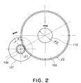
- Fig. 2 is a diagram for explaining the structure of the driving transmission means shown in Fig. 1.
- the number of teeth of the motor gear 108 is given by Z1
- the number of teeth of the conveying roller gear 109 is given by Z2
- the conveying diameter of the conveying roller 110 is given by ⁇ D.
- the conveying motor 107 is rotated by a certain angle ⁇ (rad)
- the recording sheet 115 is conveyed with the conveying roller 110 by ⁇ D ⁇ (Z1/Z2) ⁇ ( ⁇ /2 ⁇ ).
- Fig. 3 shows relation between a cogging torque ripple Tc of the conveying motor 107 acting as the DC motor and the recording sheet conveying quantity by the conveying roller.
- the longitudinal axis indicates torque (or may indicate speed), and the lateral axis indicates the recording sheet conveying quantity by the conveying roller.
- ten-period torque changes arise in a period TM of one rotation of the motor because of balance of magnetic force as shown in Fig. 3. That is, a similar torque change period Tp arises every 1/10 period of the motor.
- the torque changes (or the speed changes) might be slightly different from others due to an axial loss of the motor, mechanical balance and electrical balance, this periodicity is not greatly degraded because the period itself is determined by the structure of the motor.
- a deceleration ratio to satisfy the above expression is determined (i.e., if the number of teeth Z1 and the number of teeth Z2 are determined), as shown in Fig. 3, when the conveying of the determined conveying pitch Pf is executed, a cogging torque ripple phase angle at the motor stop is always constant.
- the motor shifts to a position X2 if the conveying of the pitch Pf is executed, and the motor further shifts to a position X3 if the conveying of the pitch Pf is further executed.
- Each stop point is at the same-phase position on the cogging torque ripple Tc.
- the cogging torque causing disturbance at each stop position is always similar or approximate, and also prestop disturbance torque is approximate every time the motor stops, whereby servo-controlled speed is substantially constant.
- the motor stop position is stable.
- the stop position deviates from the stop target (OFF timing for stopping driving of the DC motor).
- the stop position is substantially the same every time the motor stops, whereby accuracy of the conveying pitch being the relative stop position can be secured. That is, in Fig. 3, although the phase angle at each conveying pitch Pf is always 0°, the phase angle itself need not be 0°. Thus, even if another phase angle (e.g., 45°, 90°, 135° or the like) is given, it may be employed on the condition that such the phase angle be always constant.
- the basic minimum conveying pitch P is equal to the period TM of one rotation of the motor, whereby the motor can stop in the state that, as well as the period of the cogging torque ripple (cogging period), a motor one-period torque change (a torque change in the period of the motors) due to the axial loss of the motor or the motor structure is always the same, thereby further increasing accuracy.
- the deceleration ratio only has to be set, and the encoder information of the excessively small pitch used to strictly control the torque change (and the speed change) due to the cogging period is not necessary, whereby neither special parts nor the control are necessary. For this reason, restriction on the size of the codewheel and the kind of encoder is small, whereby there is a significant merit that the conveying of high accuracy can be achieved cheaply and easily.
- the whole conveying quantity Pf is matched with the integer multiple of the conveying quantity Tp corresponding to one period of the change due to the cogging
- the whole conveying quantity Pf need not necessarily be matched and the speed may be preferentially set in a skip conveying executed mode where an adjacent image area does not exist, in a high-speed recording mode where image quality is no object, and the like.
- the one-step deceleration gear as shown in Fig. 2 has been explained by way of example.
- the basic minimum conveying pitch of the sheet can be easily matched with an integer multiple of the sheet conveying quantity by the rotation of the conveying motor corresponding to one period of the cogging torque ripple of the motor.
- a belt having gear teeth a cogged belt or timing belt
- the basic minimum conveying pitch being as much as an integer multiple of the cogging torque change period is provided, and then the whole conveying quantity is set to be an integer multiple of this pitch.
- the present invention is not limited to this, and the whole conveying quantity only has to be an integer multiple of the cogging torque change period. That is, the present invention is not limited to the structure that the whole conveying quantity is an integer multiple of the basic minimum conveying pitch.
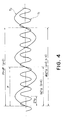
- Fig. 4 is a diagram showing relation between a torque change (speed change) (Tt) due to an interlock period of a gear and a recording sheet conveying quantity by a conveying roller.
- the longitudinal axis indicates torque (or may indicate speed), and the lateral axis indicates the recording sheet conveying quantity by the conveying roller.
- more accurate sheet conveying can be achieved by simultaneously matching the sheet conveying quantity Pf with an integer multiple of the sheet conveying quantity corresponding to one period of a cogging torque ripple Tc of the conveying motor 107.
- the present invention is not limited to these values. That is, the value a only has to be an integer even if the conveying quantity becomes variable during the recording, and the value b only has to be an integer even when the number of teeth is determined.
- the conveying quantity Pf in all modes is matched with an integer multiple of the recording sheet conveying quantity Z1p corresponding to the pitch (one period) of the torque change (speed change) due to the interlock
- the conveying quantity Pf need not necessarily be matched and the speed may be preferentially set in a skip conveying mode where an adjacent image area does not exist, in a high-speed recording mode where image quality is no object, and the like.
- the one-step deceleration gear has been explained by way of example.
- the basic minimum conveying pitch of the sheet can be easily matched with an integer multiple of the sheet conveying quantity by the rotation of the conveying motor corresponding to one period of the torque change (speed change) due to the interlock.
- a belt having gear teeth a cogged belt or timing belt
- the basic minimum conveying pitch being as much as an integer multiple of the cogging torque change period is provided, and then the whole conveying quantity is set to be an integer multiple of this pitch.
- the present invention is not limited to this, and the whole conveying quantity only has to be an integer multiple of the cogging torque change period. That is, the present invention is not limited to the structure that the whole conveying quantity is an integer multiple of the basic minimum conveying pitch.
- the conveying quantity of the recording medium by the conveying roller is matched with an integer multiple of the recording medium conveying quantity by the rotation of the conveying roller corresponding to one period of the change due to the cogging of the DC motor acting as the driving motor of the conveying roller, whereby the phase angle of the cogging torque ripple being the disturbance at the time of stopping the DC motor is always the same, the prestop speed is approximate, and thus the low-speed driving before the motor stops is stabilized and also the stop position is stabilized.
- conveying pitch accuracy can be secured, and an image of higher quality can be formed.
- the deceleration ratio of the driving transmission means only has to be set such that the conveying quantity by the conveying roller becomes an integer multiple of the recording medium conveying quantity corresponding to the cogging period of the DC motor.
- the torque change (speed change) of excessively small pitch which is hard to be controlled can be synchronized in the same manner as in case of the above change due to the cogging, whereby the conveying of higher accuracy can be achieved without increasing costs.
- a recording apparatus comprises a conveying roller for conveying a recording medium, a conveying motor for generating driving force to drive the conveying roller, a driving transmitter for transmitting the driving force of the conveying motor to the conveying roller, a detector for detecting a rotation angle of the conveying roller, and a controller for controlling driving and stopping of the conveying roller on the basis of a signal from the detector, wherein a conveying quantity of the recording medium at a time of recording operation is an integer multiple of a conveying quantity of the recording medium corresponding to one period of a torque change or a speed change caused by the conveying motor or the driving transmitter, so that stop accuracy of the recording medium is not influenced by a torque (speed) ripple of the conveying motor or the transmitter.
Landscapes
- Handling Of Sheets (AREA)
- Delivering By Means Of Belts And Rollers (AREA)
- Character Spaces And Line Spaces In Printers (AREA)
Applications Claiming Priority (2)
| Application Number | Priority Date | Filing Date | Title |
|---|---|---|---|
| JP2000332714 | 2000-10-31 | ||
| JP2000332714A JP3833060B2 (ja) | 2000-10-31 | 2000-10-31 | 記録装置 |
Publications (3)
| Publication Number | Publication Date |
|---|---|
| EP1201445A2 true EP1201445A2 (fr) | 2002-05-02 |
| EP1201445A3 EP1201445A3 (fr) | 2003-08-13 |
| EP1201445B1 EP1201445B1 (fr) | 2004-12-29 |
Family
ID=18808885
Family Applications (1)
| Application Number | Title | Priority Date | Filing Date |
|---|---|---|---|
| EP01125866A Expired - Lifetime EP1201445B1 (fr) | 2000-10-31 | 2001-10-30 | Dispositif d'enregistrement |
Country Status (4)
| Country | Link |
|---|---|
| US (1) | US6702492B2 (fr) |
| EP (1) | EP1201445B1 (fr) |
| JP (1) | JP3833060B2 (fr) |
| DE (1) | DE60108040T2 (fr) |
Cited By (1)
| Publication number | Priority date | Publication date | Assignee | Title |
|---|---|---|---|---|
| US7183730B2 (en) | 2003-05-15 | 2007-02-27 | Hewlett-Packard Development Company, L.P. | Method and apparatus for receiving and manipulating sheet material |
Families Citing this family (12)
| Publication number | Priority date | Publication date | Assignee | Title |
|---|---|---|---|---|
| FR2803929B1 (fr) * | 1999-12-30 | 2004-09-17 | Ferid Allani | Procede et dispositif pour acceder a des sources d'information et services sur le web |
| JP3809406B2 (ja) * | 2002-08-29 | 2006-08-16 | キヤノン株式会社 | 記録装置及び記録装置の制御方法 |
| JP4366150B2 (ja) | 2003-09-05 | 2009-11-18 | キヤノン株式会社 | 記録装置 |
| JP4447891B2 (ja) * | 2003-10-31 | 2010-04-07 | キヤノン株式会社 | Dcモータ制御装置および記録装置 |
| JP4470795B2 (ja) | 2005-03-30 | 2010-06-02 | ブラザー工業株式会社 | 画像形成装置 |
| JP4760090B2 (ja) | 2005-03-30 | 2011-08-31 | ブラザー工業株式会社 | 搬送装置及び画像形成装置 |
| US7837194B2 (en) | 2005-03-30 | 2010-11-23 | Brother Kogyo Kabushiki Kaisha | Feeding apparatus and image forming system |
| KR100645441B1 (ko) | 2005-05-03 | 2006-11-14 | 삼성전자주식회사 | 화상형성장치 |
| US7959248B2 (en) | 2007-06-29 | 2011-06-14 | Canon Kabushiki Kaisha | Recording apparatus and method for controlling the recording apparatus |
| JP5383118B2 (ja) | 2008-08-25 | 2014-01-08 | キヤノン株式会社 | 記録装置および搬送ローラの原点検出方法 |
| US9145014B1 (en) * | 2014-05-19 | 2015-09-29 | Eastman Kodak Company | Drive gears providing improved registration in digital printing systems |
| CN107633626A (zh) * | 2017-09-14 | 2018-01-26 | 深圳怡化电脑股份有限公司 | 介质回收设备、金融自助终端及介质回收方法 |
Family Cites Families (8)
| Publication number | Priority date | Publication date | Assignee | Title |
|---|---|---|---|---|
| JPH07311486A (ja) * | 1994-05-16 | 1995-11-28 | Fujitsu Ltd | 画像形成装置 |
| JP3686721B2 (ja) * | 1996-01-08 | 2005-08-24 | アルプス電気株式会社 | プリンタの紙送り装置およびその紙送り制御方法 |
| US5940105A (en) | 1996-01-26 | 1999-08-17 | Canon Kabushiki Kaisha | Motor drive controlling method for an image forming apparatus and motor drive controlling apparatus in the image forming apparatus using the method |
| JP3736010B2 (ja) | 1997-03-19 | 2006-01-18 | 富士ゼロックス株式会社 | 印刷装置及び用紙送り装置 |
| JP2000095386A (ja) * | 1998-09-21 | 2000-04-04 | Alps Electric Co Ltd | 紙送り制御方法 |
| JP2000272115A (ja) | 1999-03-25 | 2000-10-03 | Canon Inc | 記録装置 |
| US6364549B1 (en) * | 2000-04-27 | 2002-04-02 | Hewlett-Packard Company | Calibration of a media advanced system |
| JP2002005655A (ja) * | 2000-06-23 | 2002-01-09 | Canon Inc | 搬送ローラ搬送角度検出用のスケール製造方法及び記録装置 |
-
2000
- 2000-10-31 JP JP2000332714A patent/JP3833060B2/ja not_active Expired - Fee Related
-
2001
- 2001-10-25 US US09/983,578 patent/US6702492B2/en not_active Expired - Lifetime
- 2001-10-30 EP EP01125866A patent/EP1201445B1/fr not_active Expired - Lifetime
- 2001-10-30 DE DE60108040T patent/DE60108040T2/de not_active Expired - Lifetime
Cited By (2)
| Publication number | Priority date | Publication date | Assignee | Title |
|---|---|---|---|---|
| US7183730B2 (en) | 2003-05-15 | 2007-02-27 | Hewlett-Packard Development Company, L.P. | Method and apparatus for receiving and manipulating sheet material |
| DE102004007639B4 (de) * | 2003-05-15 | 2008-11-20 | Hewlett-Packard Development Co., L.P., Houston | Verfahren und Vorrichtung zum Aufnehmen und Manipulieren von Blattmaterial |
Also Published As
| Publication number | Publication date |
|---|---|
| JP2002128313A (ja) | 2002-05-09 |
| EP1201445A3 (fr) | 2003-08-13 |
| US6702492B2 (en) | 2004-03-09 |
| JP3833060B2 (ja) | 2006-10-11 |
| US20020051670A1 (en) | 2002-05-02 |
| EP1201445B1 (fr) | 2004-12-29 |
| DE60108040D1 (de) | 2005-02-03 |
| DE60108040T2 (de) | 2006-03-16 |
Similar Documents
| Publication | Publication Date | Title |
|---|---|---|
| US6599043B2 (en) | Control method for sheet member conveying apparatus and control method for recording apparatus | |
| EP1201445B1 (fr) | Dispositif d'enregistrement | |
| US7560892B2 (en) | Method of controlling stepping motor, apparatus for controlling stepping motor, and printer | |
| JP4886426B2 (ja) | 記録装置及び搬送制御方法 | |
| JP2005178395A (ja) | テープ駆動機構および印刷装置 | |
| JP3859115B2 (ja) | プリンタ用モータの制御装置および制御方法ならびに制御プログラムを記録した記録媒体 | |
| US6515445B2 (en) | Digital encoder control method | |
| US7784892B2 (en) | Printer and method of controlling the same | |
| EP1063093B1 (fr) | Dispositif d'alimentation en papier et imprimante utilisant ceci | |
| JP4215064B2 (ja) | ステッピングモータの制御方法、ステッピングモータの制御装置およびプリンタ | |
| JP7722008B2 (ja) | 搬送装置および画像記録装置 | |
| JP3818496B2 (ja) | プリンタ制御装置及びプリンタ制御方法 | |
| US9278561B2 (en) | Printing apparatus and printing method | |
| JP3675236B2 (ja) | 紙送り装置 | |
| JP3287516B2 (ja) | プリンタの紙送り装置 | |
| JP2006150619A (ja) | 印刷装置、コンピュータプログラム、印刷システム、及び、印刷方法 | |
| JP2006224559A (ja) | インクジェットプリンタ | |
| JP2007118304A (ja) | 記録装置 | |
| JP2007282307A (ja) | ステッピングモータの制御方法、ステッピングモータの制御装置およびプリンタ | |
| JP2004181824A (ja) | シリアル記録装置におけるラインフィード用モーター制御機構および方法 | |
| JP2007296802A (ja) | 画像形成装置 | |
| JPH07205514A (ja) | 記録装置 | |
| JP2004230565A (ja) | 印字装置 | |
| JP2008100478A (ja) | プリンタ | |
| JP2006159625A (ja) | シリアルプリンタ |
Legal Events
| Date | Code | Title | Description |
|---|---|---|---|
| PUAI | Public reference made under article 153(3) epc to a published international application that has entered the european phase |
Free format text: ORIGINAL CODE: 0009012 |
|
| AK | Designated contracting states |
Kind code of ref document: A2 Designated state(s): AT BE CH CY DE DK ES FI FR GB GR IE IT LI LU MC NL PT SE TR |
|
| AX | Request for extension of the european patent |
Free format text: AL;LT;LV;MK;RO;SI |
|
| PUAL | Search report despatched |
Free format text: ORIGINAL CODE: 0009013 |
|
| AK | Designated contracting states |
Designated state(s): AT BE CH CY DE DK ES FI FR GB GR IE IT LI LU MC NL PT SE TR |
|
| AX | Request for extension of the european patent |
Extension state: AL LT LV MK RO SI |
|
| GRAP | Despatch of communication of intention to grant a patent |
Free format text: ORIGINAL CODE: EPIDOSNIGR1 |
|
| 17P | Request for examination filed |
Effective date: 20040105 |
|
| AKX | Designation fees paid |
Designated state(s): DE FR GB IT |
|
| GRAS | Grant fee paid |
Free format text: ORIGINAL CODE: EPIDOSNIGR3 |
|
| GRAA | (expected) grant |
Free format text: ORIGINAL CODE: 0009210 |
|
| AK | Designated contracting states |
Kind code of ref document: B1 Designated state(s): DE FR GB IT |
|
| REG | Reference to a national code |
Ref country code: GB Ref legal event code: FG4D |
|
| REG | Reference to a national code |
Ref country code: IE Ref legal event code: FG4D |
|
| REF | Corresponds to: |
Ref document number: 60108040 Country of ref document: DE Date of ref document: 20050203 Kind code of ref document: P |
|
| PLBE | No opposition filed within time limit |
Free format text: ORIGINAL CODE: 0009261 |
|
| STAA | Information on the status of an ep patent application or granted ep patent |
Free format text: STATUS: NO OPPOSITION FILED WITHIN TIME LIMIT |
|
| 26N | No opposition filed |
Effective date: 20050930 |
|
| ET | Fr: translation filed | ||
| REG | Reference to a national code |
Ref country code: FR Ref legal event code: PLFP Year of fee payment: 15 |
|
| REG | Reference to a national code |
Ref country code: FR Ref legal event code: PLFP Year of fee payment: 16 |
|
| PGFP | Annual fee paid to national office [announced via postgrant information from national office to epo] |
Ref country code: DE Payment date: 20161031 Year of fee payment: 16 Ref country code: FR Payment date: 20161024 Year of fee payment: 16 Ref country code: GB Payment date: 20161021 Year of fee payment: 16 |
|
| PGFP | Annual fee paid to national office [announced via postgrant information from national office to epo] |
Ref country code: IT Payment date: 20161005 Year of fee payment: 16 |
|
| REG | Reference to a national code |
Ref country code: DE Ref legal event code: R119 Ref document number: 60108040 Country of ref document: DE |
|
| GBPC | Gb: european patent ceased through non-payment of renewal fee |
Effective date: 20171030 |
|
| REG | Reference to a national code |
Ref country code: FR Ref legal event code: ST Effective date: 20180629 |
|
| PG25 | Lapsed in a contracting state [announced via postgrant information from national office to epo] |
Ref country code: DE Free format text: LAPSE BECAUSE OF FAILURE TO SUBMIT A TRANSLATION OF THE DESCRIPTION OR TO PAY THE FEE WITHIN THE PRESCRIBED TIME-LIMIT Effective date: 20180501 Ref country code: GB Free format text: LAPSE BECAUSE OF NON-PAYMENT OF DUE FEES Effective date: 20171030 |
|
| PG25 | Lapsed in a contracting state [announced via postgrant information from national office to epo] |
Ref country code: FR Free format text: LAPSE BECAUSE OF NON-PAYMENT OF DUE FEES Effective date: 20171031 |
|
| PG25 | Lapsed in a contracting state [announced via postgrant information from national office to epo] |
Ref country code: IT Free format text: LAPSE BECAUSE OF NON-PAYMENT OF DUE FEES Effective date: 20171030 |
|
| RIC2 | Information provided on ipc code assigned after grant |
Ipc: B41J 13/00 20060101ALI20020207BHEP Ipc: B41J 11/42 20060101AFI20020207BHEP |