EP1201463A2 - Bandage pneumatique radial - Google Patents
Bandage pneumatique radial Download PDFInfo
- Publication number
- EP1201463A2 EP1201463A2 EP01125248A EP01125248A EP1201463A2 EP 1201463 A2 EP1201463 A2 EP 1201463A2 EP 01125248 A EP01125248 A EP 01125248A EP 01125248 A EP01125248 A EP 01125248A EP 1201463 A2 EP1201463 A2 EP 1201463A2
- Authority
- EP
- European Patent Office
- Prior art keywords
- bead
- ply
- reinforcing
- tire
- carcass
- Prior art date
- Legal status (The legal status is an assumption and is not a legal conclusion. Google has not performed a legal analysis and makes no representation as to the accuracy of the status listed.)
- Granted
Links
Images

Classifications
-
- B—PERFORMING OPERATIONS; TRANSPORTING
- B60—VEHICLES IN GENERAL
- B60C—VEHICLE TYRES; TYRE INFLATION; TYRE CHANGING; CONNECTING VALVES TO INFLATABLE ELASTIC BODIES IN GENERAL; DEVICES OR ARRANGEMENTS RELATED TO TYRES
- B60C15/00—Tyre beads, e.g. ply turn-up or overlap
- B60C15/0009—Tyre beads, e.g. ply turn-up or overlap features of the carcass terminal portion
- B60C15/0072—Tyre beads, e.g. ply turn-up or overlap features of the carcass terminal portion with ply reverse folding, i.e. carcass layer folded around the bead core from the outside to the inside
-
- B—PERFORMING OPERATIONS; TRANSPORTING
- B60—VEHICLES IN GENERAL
- B60C—VEHICLE TYRES; TYRE INFLATION; TYRE CHANGING; CONNECTING VALVES TO INFLATABLE ELASTIC BODIES IN GENERAL; DEVICES OR ARRANGEMENTS RELATED TO TYRES
- B60C15/00—Tyre beads, e.g. ply turn-up or overlap
- B60C15/0009—Tyre beads, e.g. ply turn-up or overlap features of the carcass terminal portion
- B60C15/0018—Tyre beads, e.g. ply turn-up or overlap features of the carcass terminal portion not folded around the bead core, e.g. floating or down ply
-
- B—PERFORMING OPERATIONS; TRANSPORTING
- B60—VEHICLES IN GENERAL
- B60C—VEHICLE TYRES; TYRE INFLATION; TYRE CHANGING; CONNECTING VALVES TO INFLATABLE ELASTIC BODIES IN GENERAL; DEVICES OR ARRANGEMENTS RELATED TO TYRES
- B60C15/00—Tyre beads, e.g. ply turn-up or overlap
- B60C15/06—Flipper strips, fillers, or chafing strips and reinforcing layers for the construction of the bead
-
- Y—GENERAL TAGGING OF NEW TECHNOLOGICAL DEVELOPMENTS; GENERAL TAGGING OF CROSS-SECTIONAL TECHNOLOGIES SPANNING OVER SEVERAL SECTIONS OF THE IPC; TECHNICAL SUBJECTS COVERED BY FORMER USPC CROSS-REFERENCE ART COLLECTIONS [XRACs] AND DIGESTS
- Y10—TECHNICAL SUBJECTS COVERED BY FORMER USPC
- Y10T—TECHNICAL SUBJECTS COVERED BY FORMER US CLASSIFICATION
- Y10T152/00—Resilient tires and wheels
- Y10T152/10—Tires, resilient
- Y10T152/10495—Pneumatic tire or inner tube
- Y10T152/10819—Characterized by the structure of the bead portion of the tire
- Y10T152/10837—Bead characterized by the radial extent of apex, flipper or chafer into tire sidewall
Definitions
- the present invention relates to a pneumatic radial tire suitable for use as a high performance tire particularly aimed to run on circuits and being capable of improving initial response characteristics at the time of steering and of achieving cuts in running times by restricting deformation owing to torsion at bead portions thereof.
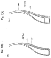
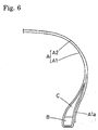
- a 1-1 structure is often employed for the purpose of improving lateral rigidity and of securing cornering force wherein a carcass A is formed of an inner carcass ply A1 (so-called inner ply) that is fold up from inside to outside around a bead core B and an outer carcass ply A2 (so-called outer ply) that is overlapped with and connected to the fold-up portion Ala of the inner carcass ply A1 by being extending inwardly to the outside of the bead core B as schematically illustrated in Fig. 6.
- the inventor supposed that deformation owing to torsion of the bead portions in an initial stage of steering is a large factor thereof. More particularly, while movements are transmitted at the time of steering from a wheel rim to the bead portions, from the bead portions to the side wall portion, and from the side wall portion to a tread portion in this order, it is assumed that occurrence of torsional deformation of a pulled portion of the bead portions or bead cores at the initial stage of steering, causes a delay in transmission of movements to the tires.
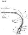
- Fig. 1 is a sectional view of a tire according to one embodiment of the present invention.
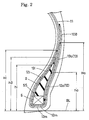
- Fig. 2 is a sectional view in which a bead portion thereof is illustrated in an enlarged manner.
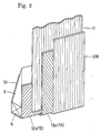
- Fig. 3 is a perspective view for schematically showing a cord arrangement of the bead portions.
- Fig. 4 is a sectional view illustrating another embodiment of the second bead reinforcing layer.
- Fig. 5(A) and Fig. 5(B) are sectional views illustrating still another embodiment of the second bead reinforcing layer.
- Fig. 6 is a sectional view for explaining a prior art.
- Fig. 1 is a meridian sectional view of the pneumatic radial tire of the present invention, which is a high performance tire of a size of 225/45R16 for use in a passenger car.
- the pneumatic radial tire 1 (hereinafter referred to as "tire 1") includes a tread portion 2, a pair of side wall portions 3 inwardly extending radially from both ends of the tread portion 2, and bead portions 4 located at inner ends of the respective side wall portions 3.
- the tire 1 is further provided with a carcass 6 extending to bridge over the bead portions 4,4 and a belt layer 7 that is disposed inward of the tread portion 2 and outside of the carcass 6 in a radial direction.
- the carcass 6 has a 1-1 structure consisting of an inner carcass ply 10 disposed on inner side i facing an tire inner space and an outer carcass ply 11 disposed outside thereof.
- the inner carcass ply 10 is arranged in that a ply fold-up portion 10B, which is fold up from inside to outside of the tire around the bead core 5, is integrally formed with a ply main body portion 10A that extends from the tread portion 2 over the side wall portions 3 to the bead cores 5 of the bead portions 4.
- a bead apex rubber 9 is provided between the ply main body portion 10A and the ply fold-up portion 10B to outwardly extend in a radial direction in a tapered manner from an upper surface 5S of the bead core 5.
- the bead apex rubber 9 might suitably be formed of hard rubber having a durometer A hardness of 80 to 96 degrees, similar to the prior art, for reinforcing regions extending from the bead portions 4 to the side wall portions 3.
- the outer carcass ply 11 extends inwardly in a radial direction from the tread portion 2 over the side wall portions 3 and is rolled down between the bead apex rubber 9 and the ply fold-up portion 10B to be engaged thereat.
- An inner end of the outer carcass ply 11 in this preferred embodiment terminates in a height region between the upper surface 5S and the bottom surface of the bead core 5, and a fold-up end of the inner carcass ply 10 (outer end of the ply fold-up portion 11B) terminates in a height region between a maximum width position P of the tire and a tread end.
- the inner and outer carcass plies 10, 11 include carcass cords respectively arranged at angles of 70 to 90 degrees with respect to a peripheral direction of the tire, and suitable materials that might be employed for such carcass cords are organic fiber cords such as those made of nylon, polyester, rayon or aromatic polyamide.
- the belt layer 7 consists of two or more of highly elastic belt cords such as aromatic polyamide fiber cords or steel cords that are arranged at angles of 10 to 35 with respect to a peripheral direction of the tire, and in this embodiment, of two inner and outer belt plies 7A, 7B.
- the belt cords are disposed at different directions of arrangements such that they intersect between the plies and thereby to reinforce the tread portion 2 and to improve its tread rigidity substantially over its entire width owing to the strong hoop effects.
- a band layer (not shown) further outside of the belt layer 7 in which organic fiber cords such as those made of nylon are, for instance, spirally wound at an angle of 5 degrees or less with respect to a peripheral direction of the tire for the purpose of preventing lifting of the tread portion 2 accompanying high speed running.
- the bead portions 4 are equipped with first and second reinforcing layers 12, 13 for the purpose of restricting torsional deformation of the bead portions 4.
- the first bead reinforcing layer 12 is formed of a single reinforcing ply 22 having reinforcing cords inclining at cord angles of 15 to 60 degrees with respect to a peripheral direction of the tire, wherein the reinforcing ply 22 may be made of a fabric material in which the reinforcing cords are used as warps that are arranged to be parallel to each other, or of a textile material in which the reinforcing cords are used as warps/wefts that are woven in a lattice-like shape. As for the textile material, at least one group of the reinforcing cords (warps or wefts) should be disposed at an angle within the above range (15 to 60 degrees) . While the reinforcing cords may be organic fiber cords or steel cords, suitably used organic fiber cords are those of nylon or aromatic polyamide wherein the latter is more suitable.
- the first bead reinforcing layer 12 is formed such a U-letter shape wherein an inner turn up portion 12i adjoining an inner surface of the bead apex rubber 9 and an outer turn up portion 12o adjoining an outer surface of the bead apex rubber 9, are provided and connected to both sides of a base portion 12m extending through the bottom surface of the bead core 5. More particularly, the first bead reinforcing layer 12 enwraps the bead core 5 and the bead apex layer 9 in a closely fitted manner for firmly bonding both members in an integral manner.
- a height hi from a base bead line BL at an outer end of the inner turn up portion 12i in a radial direction is smaller than a height h9 of an outer end of the bead apex rubber 9 but larger than a height ho of an outer end of the outer turn up portion 12o, that is, in which h9>hi>ho is satisfied.
- T he "bead base line BL" is a line parallel to a tire axis passing through an intersection of the extension of a bead bottom surface and a bead outer surface of the tire and indicates a nominal rim diameter.
- the second bead reinforcing layer 13 is similarly formed of a single reinforcing ply 23 including reinforcing cords inclining at cord angles of 15 to 60 degrees with respect to a peripheral direction of the tire.
- the reinforcing cords are disposed at different cord angles or directions of inclination such that they intersect with the reinforcing cords of the reinforcing ply 22. Therefore, a firm truss structure is formed by the respectively intersecting reinforcing cords in cooperation with the carcass cords at regions where the reinforcing plies 22, 23 overlap to thus exhibit strong torsion rigidity, and possible to effectively restrict torsional deformation of the bead core 5.
- the reinforcing ply 23 may be made of a fabric material in which the respective reinforcing cords are used as warps and are arranged to be parallel to each other, or of a textile material in which the reinforcing cords are used as warps/wefts and are woven in a lattice-like shape, wherein in case of employing a textile material, at least one group of the reinforcing cords shall be disposed at an angle within the above range (15 to 60 degrees). While the reinforcing cords may be organic fiber cords or steel cords, suitably used organic fiber cords are those of nylon or aromatic polyamide wherein the latter is particularly suitable.
- the second bead reinforcing layer 13 has an outer piece portion 13o which extends from a position beyond the outer end of the outer turn up portion 12o to exceed inwardly the upper surface 5S of the bead core 5 to inside in the radial direction, it overlaps with the outer turn up portion 120 outwardly in an axial direction of the tire.
- This overlapping region at least outside of the bead apex rubber 9 in an axial direction of the tire and covering the outer end of the outer turn up portion 12o of the U-shaped first bead reinforcing layer 12 enwrapping the bead core 5 by the outer piece portion 13o is both effective in restricting torsional deformation of the bead portions 4.
- the second bead reinforcing layer 13 is shaped in U-letter form in which the outer piece portion 13o is extended to the base piece portion 13m and the inner piece portion 13i that respectively overlap the base portion 12m and the inner turn up portion 12i.
- the heights Hi, Ho of the respective outer ends of the inner piece portion 13i and the outer piece portion 13o from the bead base line BL are set such that that they are at least larger than the heights hi, ho, that is, that Hi>hi and Ho>ho is satisfied, so that the second bead reinforcing layer 13 will further cover the first bead reinforcing layer 12 in an enwrapping manner.
- it is arranged to satisfy Hi > h9 > hi, Ho > h9 > ho.
- both bead reinforcing layers 12, 13 By forming both bead reinforcing layers 12, 13 to be in a U-shaped form, it is possible to increase overlapping regions and since these regions successively enclose substantially the entire periphery of the bead core 5 and the bead apex rubber 9, and to further improve effects of restricting torsional deformation.
- the outer piece portion 13o is interposed between the ply fold-up portion 10B and the outer carcass ply 11 such that four layers, namely the outer turn up portion 12o, the outer carcass ply 11, the outer piece portion 13o and the ply fold-up portion 10B are sequentially overlaid from inside to outside in an axial direction of the tire.
- four layers namely the outer turn up portion 12o, the outer carcass ply 11, the outer piece portion 13o and the ply fold-up portion 10B are sequentially overlaid from inside to outside in an axial direction of the tire.
- the outer piece portion 13o might also be interposed between the outer turn up'portion 12o and the outer carcass ply 11, while such an arrangement is somewhat inferior as a truss structure than the former one since the cords will not intersect between the adjoining outer carcass ply 11 and the ply fold-up portion 10B.
- the reinforcing cords employed in the reinforcing plies 22, 23 shall have a diameter of 0.4 to 0.7 mm in case they are steel cords; in case they are aromatic polyamide fiber cords, those having a size of 1,100 to 1,800 dtex may be suitable employed.
- Prototypes of a high performance passenger car tire of size of 225/45R16 shown in fig. 1 were manufactured according to the specifications of Table 1, and initial response characteristics of the respective prototype tires at steering were compared depending on running time on a circuit.
- the tires are of identical specifications except the points listed in Table 1.
- Prototype tires were attached to all wheels of a vehicle (2,000 cc: FR vehicle) with conditions for a rim being 7.5 J ⁇ 16 and for an internal pressure 250 kPa, wherein a time trial was made on a circuit course (paved road) for measuring a running time thereof.
- the tire of the embodiments in which especially the second bead reinforcing layer is in a U-shaped while matching with a carcass of 1-1 structure was capable of restricting torsional deformation of bead portions and of achieving improvements in initial response characteristics of steering so that the running time was shortened.
Landscapes
- Engineering & Computer Science (AREA)
- Mechanical Engineering (AREA)
- Tires In General (AREA)
Applications Claiming Priority (2)
| Application Number | Priority Date | Filing Date | Title |
|---|---|---|---|
| JP2000333093 | 2000-10-31 | ||
| JP2000333093A JP3493173B2 (ja) | 2000-10-31 | 2000-10-31 | 空気入りラジアルタイヤ |
Publications (3)
| Publication Number | Publication Date |
|---|---|
| EP1201463A2 true EP1201463A2 (fr) | 2002-05-02 |
| EP1201463A3 EP1201463A3 (fr) | 2003-04-09 |
| EP1201463B1 EP1201463B1 (fr) | 2005-09-14 |
Family
ID=18809223
Family Applications (1)
| Application Number | Title | Priority Date | Filing Date |
|---|---|---|---|
| EP01125248A Expired - Lifetime EP1201463B1 (fr) | 2000-10-31 | 2001-10-24 | Bandage pneumatique radial |
Country Status (4)
| Country | Link |
|---|---|
| US (1) | US6834698B2 (fr) |
| EP (1) | EP1201463B1 (fr) |
| JP (1) | JP3493173B2 (fr) |
| DE (1) | DE60113361T2 (fr) |
Cited By (4)
| Publication number | Priority date | Publication date | Assignee | Title |
|---|---|---|---|---|
| US8413700B2 (en) | 2010-02-04 | 2013-04-09 | Bridgestone Americas Tire Operations, Llc | Tire having staggered turn-ups |
| US8517072B2 (en) | 2010-02-04 | 2013-08-27 | Bridgestone Americas Tire Operations, Llc | Tire having gum strip and chafer |
| WO2018044605A1 (fr) * | 2016-08-30 | 2018-03-08 | Bridgestone Americas Tire Operations, Llc | Pneumatique |
| EP3895916A1 (fr) * | 2020-04-17 | 2021-10-20 | Sumitomo Rubber Industries, Ltd. | Pneumatique |
Families Citing this family (8)
| Publication number | Priority date | Publication date | Assignee | Title |
|---|---|---|---|---|
| JP5167599B2 (ja) * | 2006-06-30 | 2013-03-21 | 横浜ゴム株式会社 | 空気入りタイヤ |
| US20120085476A1 (en) * | 2010-10-07 | 2012-04-12 | Yves Donckels | Pneumatic tire with a woven or knitted bead reinforcement |
| KR102590070B1 (ko) * | 2015-10-15 | 2023-10-16 | 스미토모 고무 코교 카부시키카이샤 | 공기 타이어 |
| KR101849234B1 (ko) * | 2016-12-28 | 2018-05-28 | 넥센타이어 주식회사 | 래디얼 타입 레이싱 타이어 이중 체이퍼 구조 |
| KR101981892B1 (ko) * | 2018-06-15 | 2019-05-23 | 한국타이어 주식회사 | 공기압 타이어의 비드 보강 장치 |
| FI4461565T3 (fi) * | 2023-05-08 | 2025-11-19 | Nokian Renkaat Oyj | Nastarengas, jolla on pienempi tien kuluttavuus |
| CN117246075A (zh) * | 2023-10-24 | 2023-12-19 | 山东玲珑轮胎股份有限公司 | 提升全钢载重子午线轮胎胎圈耐久性的双钢丝补强层结构 |
| JP2025137108A (ja) * | 2024-03-08 | 2025-09-19 | 住友ゴム工業株式会社 | 空気入りタイヤ |
Family Cites Families (9)
| Publication number | Priority date | Publication date | Assignee | Title |
|---|---|---|---|---|
| US2971553A (en) * | 1957-03-04 | 1961-02-14 | Firestone & Tire & Rubber Comp | Tire construction |
| IT1112231B (it) * | 1979-04-10 | 1986-01-13 | Pirelli | Perfezionamento ai pneumatici radiali provvisti di struttura di irrigidimento nei fianchi |
| JPS584610A (ja) * | 1981-06-27 | 1983-01-11 | Yokohama Rubber Co Ltd:The | ラジアルタイヤ |
| US4896709A (en) * | 1987-04-17 | 1990-01-30 | The Goodyear Tire & Rubber Company | Pneumatic tire including square woven bead reinforcing layers |
| FR2615453B1 (fr) * | 1987-05-21 | 1990-07-20 | Bridgestone Corp | Pneumatique a carcasse radiale a talons renforces |
| JPH0253613A (ja) * | 1988-08-11 | 1990-02-22 | Sumitomo Rubber Ind Ltd | タイヤ |
| US5479977A (en) * | 1992-10-30 | 1996-01-02 | Sumitomo Rubber Industries, Ltd. | Pneumatic tire with carcass structure for increased sidewall rigidity |
| JP3393520B2 (ja) * | 1994-06-10 | 2003-04-07 | 住友ゴム工業株式会社 | 空気入りラジアルタイヤの製造方法 |
| JP2000190714A (ja) | 1998-12-25 | 2000-07-11 | Sumitomo Rubber Ind Ltd | 空気入りタイヤ |
-
2000
- 2000-10-31 JP JP2000333093A patent/JP3493173B2/ja not_active Expired - Fee Related
-
2001
- 2001-10-24 EP EP01125248A patent/EP1201463B1/fr not_active Expired - Lifetime
- 2001-10-24 DE DE60113361T patent/DE60113361T2/de not_active Expired - Fee Related
- 2001-10-31 US US09/984,893 patent/US6834698B2/en not_active Expired - Fee Related
Cited By (7)
| Publication number | Priority date | Publication date | Assignee | Title |
|---|---|---|---|---|
| US8413700B2 (en) | 2010-02-04 | 2013-04-09 | Bridgestone Americas Tire Operations, Llc | Tire having staggered turn-ups |
| US8517072B2 (en) | 2010-02-04 | 2013-08-27 | Bridgestone Americas Tire Operations, Llc | Tire having gum strip and chafer |
| US9440499B2 (en) | 2010-02-04 | 2016-09-13 | Bridgestone Americas Tire Operations, Llc | Tire having gum strip and chafer |
| WO2018044605A1 (fr) * | 2016-08-30 | 2018-03-08 | Bridgestone Americas Tire Operations, Llc | Pneumatique |
| US11046124B2 (en) | 2016-08-30 | 2021-06-29 | Bridgestone Americas Tire Operations, Llc | Pneumatic tire |
| EP3895916A1 (fr) * | 2020-04-17 | 2021-10-20 | Sumitomo Rubber Industries, Ltd. | Pneumatique |
| US11850892B2 (en) | 2020-04-17 | 2023-12-26 | Sumitomo Rubber Industries, Ltd. | Pneumatic tire |
Also Published As
| Publication number | Publication date |
|---|---|
| DE60113361T2 (de) | 2006-06-14 |
| JP3493173B2 (ja) | 2004-02-03 |
| US6834698B2 (en) | 2004-12-28 |
| JP2002137608A (ja) | 2002-05-14 |
| DE60113361D1 (de) | 2005-10-20 |
| EP1201463A3 (fr) | 2003-04-09 |
| EP1201463B1 (fr) | 2005-09-14 |
| US20020074072A1 (en) | 2002-06-20 |
Similar Documents
| Publication | Publication Date | Title |
|---|---|---|
| JP4046502B2 (ja) | 空気入りラジアルタイヤ | |
| US2895525A (en) | Pneumatic tire | |
| EP0778161B1 (fr) | Pneumatique et procédé de fabrication | |
| US4100955A (en) | Pneumatic tire | |
| EP0344086A2 (fr) | Bandage pneumatique | |
| US7128114B2 (en) | Pneumatic tire and method of manufacturing the tire | |
| JP7363937B2 (ja) | 重荷重用空気入りタイヤ | |
| EP1201463B1 (fr) | Bandage pneumatique radial | |
| JPH1170802A (ja) | 空気入りラジアルタイヤ | |
| JPS63279907A (ja) | 重量車用空気入りタイヤ | |
| EP1938959A1 (fr) | Pneu doté d'une structure de pli et revers d'enveloppe composites | |
| EP1094956B1 (fr) | Pneu pour roulage a plat avec toile sous-jacente visant a renforcer la rigidite meridienne et circonferentielle de la bande de roulement et procede de fabrication | |
| JPH0466309A (ja) | 空気入りタイヤ | |
| EP0301093B1 (fr) | Pneu a carcasse radiale destine aux charges elevees, a amortissement de vibrations ameliore | |
| CN1982091A (zh) | 具有改进的高速性能的轮胎以及制造方法 | |
| JP4938327B2 (ja) | 航空機用ラジアルタイヤ、及び、航空機用ラジアルタイヤの製造方法 | |
| JP2002002216A (ja) | 空気入りタイヤ | |
| JP2643085B2 (ja) | 空気入りタイヤ及びその製造方法 | |
| JP3609568B2 (ja) | 自動二輪車用の空気入りタイヤ | |
| JPH05238208A (ja) | 空気入りタイヤ | |
| JP3101605B2 (ja) | 重荷重、小型トラック用の空気入りタイヤ | |
| JPH04254204A (ja) | 空気入りタイヤ | |
| JP3715058B2 (ja) | 空気入りタイヤ | |
| EP1488939A1 (fr) | Pneumatique | |
| JP2892927B2 (ja) | 空気入りラジアルタイヤ |
Legal Events
| Date | Code | Title | Description |
|---|---|---|---|
| PUAI | Public reference made under article 153(3) epc to a published international application that has entered the european phase |
Free format text: ORIGINAL CODE: 0009012 |
|
| AK | Designated contracting states |
Kind code of ref document: A2 Designated state(s): AT BE CH CY DE DK ES FI FR GB GR IE IT LI LU MC NL PT SE TR |
|
| AX | Request for extension of the european patent |
Free format text: AL;LT;LV;MK;RO;SI |
|
| PUAL | Search report despatched |
Free format text: ORIGINAL CODE: 0009013 |
|
| AK | Designated contracting states |
Kind code of ref document: A3 Designated state(s): AT BE CH CY DE DK ES FI FR GB GR IE IT LI LU MC NL PT SE TR |
|
| AX | Request for extension of the european patent |
Extension state: AL LT LV MK RO SI |
|
| 17P | Request for examination filed |
Effective date: 20031008 |
|
| AKX | Designation fees paid |
Designated state(s): DE FR GB |
|
| 17Q | First examination report despatched |
Effective date: 20040203 |
|
| GRAP | Despatch of communication of intention to grant a patent |
Free format text: ORIGINAL CODE: EPIDOSNIGR1 |
|
| GRAS | Grant fee paid |
Free format text: ORIGINAL CODE: EPIDOSNIGR3 |
|
| GRAA | (expected) grant |
Free format text: ORIGINAL CODE: 0009210 |
|
| AK | Designated contracting states |
Kind code of ref document: B1 Designated state(s): DE FR GB |
|
| REG | Reference to a national code |
Ref country code: GB Ref legal event code: FG4D |
|
| REF | Corresponds to: |
Ref document number: 60113361 Country of ref document: DE Date of ref document: 20051020 Kind code of ref document: P |
|
| ET | Fr: translation filed | ||
| PLBE | No opposition filed within time limit |
Free format text: ORIGINAL CODE: 0009261 |
|
| STAA | Information on the status of an ep patent application or granted ep patent |
Free format text: STATUS: NO OPPOSITION FILED WITHIN TIME LIMIT |
|
| 26N | No opposition filed |
Effective date: 20060615 |
|
| PGFP | Annual fee paid to national office [announced via postgrant information from national office to epo] |
Ref country code: GB Payment date: 20061018 Year of fee payment: 6 |
|
| PGFP | Annual fee paid to national office [announced via postgrant information from national office to epo] |
Ref country code: DE Payment date: 20061019 Year of fee payment: 6 |
|
| GBPC | Gb: european patent ceased through non-payment of renewal fee |
Effective date: 20071024 |
|
| PG25 | Lapsed in a contracting state [announced via postgrant information from national office to epo] |
Ref country code: DE Free format text: LAPSE BECAUSE OF NON-PAYMENT OF DUE FEES Effective date: 20080501 |
|
| REG | Reference to a national code |
Ref country code: FR Ref legal event code: ST Effective date: 20080630 |
|
| PGFP | Annual fee paid to national office [announced via postgrant information from national office to epo] |
Ref country code: FR Payment date: 20061010 Year of fee payment: 6 |
|
| PG25 | Lapsed in a contracting state [announced via postgrant information from national office to epo] |
Ref country code: GB Free format text: LAPSE BECAUSE OF NON-PAYMENT OF DUE FEES Effective date: 20071024 |
|
| PG25 | Lapsed in a contracting state [announced via postgrant information from national office to epo] |
Ref country code: FR Free format text: LAPSE BECAUSE OF NON-PAYMENT OF DUE FEES Effective date: 20071031 |