EP1201595A2 - Coulisseau de levage, en particulier tablier porteur de fourche, et procédé pour fabriquer un coulisseau de levage - Google Patents
Coulisseau de levage, en particulier tablier porteur de fourche, et procédé pour fabriquer un coulisseau de levage Download PDFInfo
- Publication number
- EP1201595A2 EP1201595A2 EP01109170A EP01109170A EP1201595A2 EP 1201595 A2 EP1201595 A2 EP 1201595A2 EP 01109170 A EP01109170 A EP 01109170A EP 01109170 A EP01109170 A EP 01109170A EP 1201595 A2 EP1201595 A2 EP 1201595A2
- Authority
- EP
- European Patent Office
- Prior art keywords
- lifting carriage
- lifting
- carriage according
- carriage
- receiving
- Prior art date
- Legal status (The legal status is an assumption and is not a legal conclusion. Google has not performed a legal analysis and makes no representation as to the accuracy of the status listed.)
- Withdrawn
Links
- 238000004519 manufacturing process Methods 0.000 title claims description 20
- 238000000034 method Methods 0.000 title claims description 10
- 239000000725 suspension Substances 0.000 claims abstract description 4
- 238000005266 casting Methods 0.000 claims description 8
- 229910001018 Cast iron Inorganic materials 0.000 claims description 5
- 239000000463 material Substances 0.000 claims description 5
- 229910001141 Ductile iron Inorganic materials 0.000 claims description 4
- 238000007669 thermal treatment Methods 0.000 claims description 2
- OKTJSMMVPCPJKN-UHFFFAOYSA-N Carbon Chemical compound [C] OKTJSMMVPCPJKN-UHFFFAOYSA-N 0.000 claims 3
- 229910002804 graphite Inorganic materials 0.000 claims 3
- 239000010439 graphite Substances 0.000 claims 3
- 238000003466 welding Methods 0.000 description 5
- 238000010276 construction Methods 0.000 description 3
- 238000011161 development Methods 0.000 description 2
- 230000008030 elimination Effects 0.000 description 2
- 238000003379 elimination reaction Methods 0.000 description 2
- 238000013461 design Methods 0.000 description 1
- 238000006073 displacement reaction Methods 0.000 description 1
- 238000012545 processing Methods 0.000 description 1
- 238000007493 shaping process Methods 0.000 description 1
- 238000003860 storage Methods 0.000 description 1
- 238000012549 training Methods 0.000 description 1
Images


Classifications
-
- B—PERFORMING OPERATIONS; TRANSPORTING
- B66—HOISTING; LIFTING; HAULING
- B66F—HOISTING, LIFTING, HAULING OR PUSHING, NOT OTHERWISE PROVIDED FOR, e.g. DEVICES WHICH APPLY A LIFTING OR PUSHING FORCE DIRECTLY TO THE SURFACE OF A LOAD
- B66F9/00—Devices for lifting or lowering bulky or heavy goods for loading or unloading purposes
- B66F9/06—Devices for lifting or lowering bulky or heavy goods for loading or unloading purposes movable, with their loads, on wheels or the like, e.g. fork-lift trucks
- B66F9/075—Constructional features or details
- B66F9/08—Masts; Guides; Chains
Definitions
- the invention relates to a lifting carriage, in particular fork carriage for Industrial truck, consisting of a front plate for receiving a Load handler and a mounting flange for mounting the lifting carriage a lifting device.
- the invention also relates to a method of manufacture a lifting carriage.
- Lift carriage is designed as a fork carriage and consists of an upper and a lower guide profile.
- the front panel is used to hold a load handler. Forks or an attachment, for example, a sideshift or a rotating device.
- the lifting carriage is made up of several individual parts assembled, for example two legs, an upper and a lower Guide profile and, if applicable, vertical webs connecting the guide profiles.
- the assembly of the individual components, some of which are forged can be formed takes place in known lifting carriages by means of welding.
- the present invention has for its object a lifting carriage and a To provide a method for manufacturing a lifting carriage that a enable low manufacturing costs and lower manufacturing costs.
- This object is achieved with respect to the lifting carriage in that the lifting carriage is made in one piece.
- the configuration of the lifting carriage as a component results in a simple one Manufacturing with low manufacturing costs and low manufacturing costs, because on elaborate welds can be dispensed with and not one with several Components welded lifting carriage necessary straightening process is required.
- the lifting carriage is as Cast component formed.
- the lifting carriage by casting in a simple way the lifting carriage by exhausting the degrees of freedom of the Casting in terms of shape to specific requirements of the application be adjusted.
- a lifting slide produced by casting points through the Elimination of the assembly of several components and the elimination of the Straightening process on low manufacturing costs and low manufacturing costs.
- a lifting carriage in which the receiving flange of two spaced vertical legs is formed, there are special Advantages if there is at least one bearing journal on each of the legs a guide roller is arranged.
- Screwable journals can be provided on the legs.
- the bearing journal is integral with the Legs are formed.
- the journals for the guide rollers are thus at a lifting slide designed as a cast component has already been cast on, as a result of which results in low construction costs and high stability in the area of the bearing journal.
- only the cast-on bearing journals are used Editing a leadership role.
- only the journal for the upper or lower guide rollers or the journals for the upper and lower guide rollers are formed on the legs.
- the front panel as an upper and a lower horizontal guide profile is formed, there is a simple design of the lifting carriage arranged as a fork carriage on which fork tines or various attachments that can be used universally.
- Safety devices are expedient in the area of the upper guide profile trained for the load handler. By cast on Securing devices, for example several grooves, can easily be Forks must be secured against slipping sideways.
- a fastening element especially for a chain holder, designed for a lifting chain.
- a chain holder for a lifting chain can thus be attached to the lifting carriage or formed in one piece on the lifting carriage become. Due to the degrees of freedom of casting can easily Chain holder for a lifting chain can be provided on the lifting carriage.
- the lifting carriage can be tilted is provided relative to the mast of the industrial truck, there is a small Construction effort, if on the legs each have a receiving device for one Tilting device provided with guide rollers, in particular an eccentric shaft is.
- a receiving device for one Tilting device provided with guide rollers, in particular an eccentric shaft is.
- Through cast-on receiving devices, for example half shells for one Storage of an eccentric shaft forming the tilting device can be done in a simple manner Way an eccentric shaft which enables the tilting of the lifting carriage Lifting carriage can be rotatably supported.
- a mounting flange for the tilting device is expedient here actuating drive, for example a hydraulic cylinder.
- drive for example a hydraulic cylinder.
- the lifting carriage as a cast component can be a mounting flange for one drive designed as a hydraulic cylinder, for example a fastening fork, can be easily cast on the lifting slide.
- the view of that arranged on the lifting slide Load suspension devices are improved. With a cast lifting carriage, they are Openings can be produced in a simple manner using appropriate cores.
- the object is achieved in that the Lifting carriage is poured.
- a cast lifting carriage has low manufacturing costs and a low manufacturing cost. It is also by casting manufactured lifting sled possible in a simple manner by inserting different cores in a mold different variants of lifting slides for manufacture different types of industrial trucks.
- a cast lifting carriage used as spheroidal graphite cast iron.
- Spheroidal graphite cast iron points high strength and toughness and is particularly suitable for one Lifting.
- the material is austenitic - bainitic Ductile iron is used.
- An austenitic - bainitic cast iron has a high elongation at break and high strength values.
- the lifting carriage can are subjected to a thermal treatment sequence after casting, which the structure changes in such a way that the material properties are improved become.
- a lifting sled cast from austenitic - bainitic cast iron is thus comparable in material properties to a welded one Lifting carriage, with lower manufacturing costs due to the production by casting and a low manufacturing cost and high degrees of freedom in terms of Shaping are made possible.
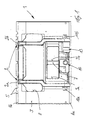
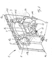
- FIG. 1 to 4 show a lifting carriage 1 designed as a fork carriage two forming a receiving flange 2 on a lifting device, no longer shown, spaced vertical legs 2a, 2b and a front panel 3.
- the Lift carriage 1 is in one piece and designed as a cast component.
- the front plate 3 has a lower horizontal guide profile 4a and an upper one horizontal guide profile 4b, by means of which as a fork or as Attachment-designed load suspension device, not shown, on the lifting carriage 1 can be attached.
- the upper guide profile 4b is with several as grooves trained safety devices 5 provided, by means of which fork tines against lateral displacement can be secured.
- the front panel 3 is designed such that in the upper region of the front panel 3 an opening 8 is provided. In the lower area of the front panel 3 is another Opening formed by means of a central, vertical strut 7 in lateral Openings 9a, 9b is divided.
- the opening 8, 9a, 9b allow the view of the Driver through the front plate 3 on the forks or the attachment.
- a bearing pin 10a, 10b in the lower region molded onto which, after mechanical processing, a lower guide roller can be rotatably attached.
- receiving devices 11a designed as semicircular bearing shells, 11b, in which a tilting device, which is no longer shown, for example an eccentric shaft which is provided with upper guide rollers, can be arranged.
- the receiving devices 11a, 11b further comprise each have a flange surface 12a, 12b formed on the legs 2a, 2b, by means of the a further bearing shells are attached to the corresponding leg 2a, 2b can.
- a tilting device designed as an eccentric shaft, on which the Upper guide rollers are arranged, so the fork carriage relative to Mast are tilted.
- An actuating device for example as Hydraulic cylinder trained drive can on a mounting flange 13, the Fork is formed and arranged in the lower region of the fork carrier on which Fork brackets are supported ..
- the fork carrier By designing the fork carrier as a cast component, it is simple possible, for stiffening between the legs 2a, 2b and the front plate 3 Struts 15a, 15b, 16a, 16b forming stiffening ribs. You can also in a simple manner, the bearing pins 10a, 10b, the fastener 14, the Mounting flange 13, the bearing shells 11a, 11b with the flange surfaces 12a, 12b and the openings 8, 9a, 9b are formed on the fork carriage 1.
Landscapes
- Engineering & Computer Science (AREA)
- Transportation (AREA)
- Structural Engineering (AREA)
- Civil Engineering (AREA)
- Life Sciences & Earth Sciences (AREA)
- Geology (AREA)
- Mechanical Engineering (AREA)
- Forklifts And Lifting Vehicles (AREA)
Applications Claiming Priority (2)
| Application Number | Priority Date | Filing Date | Title |
|---|---|---|---|
| DE10018990 | 2000-04-17 | ||
| DE2000118990 DE10018990A1 (de) | 2000-04-17 | 2000-04-17 | Hubschlitten, insbesondere Gabelträger und Verfahren zur Herstellung eines Hubschlittens |
Publications (2)
| Publication Number | Publication Date |
|---|---|
| EP1201595A2 true EP1201595A2 (fr) | 2002-05-02 |
| EP1201595A3 EP1201595A3 (fr) | 2003-05-28 |
Family
ID=7639043
Family Applications (1)
| Application Number | Title | Priority Date | Filing Date |
|---|---|---|---|
| EP01109170A Withdrawn EP1201595A3 (fr) | 2000-04-17 | 2001-04-12 | Coulisseau de levage, en particulier tablier porteur de fourche, et procédé pour fabriquer un coulisseau de levage |
Country Status (3)
| Country | Link |
|---|---|
| EP (1) | EP1201595A3 (fr) |
| JP (1) | JP2001302193A (fr) |
| DE (1) | DE10018990A1 (fr) |
Cited By (2)
| Publication number | Priority date | Publication date | Assignee | Title |
|---|---|---|---|---|
| CN107934850A (zh) * | 2017-12-31 | 2018-04-20 | 荣成中磊石材有限公司 | 一种双向调节货叉 |
| CN108689343A (zh) * | 2017-04-06 | 2018-10-23 | 海斯特-耶鲁集团有限公司 | 用于叉式托架的侧板 |
Families Citing this family (3)
| Publication number | Priority date | Publication date | Assignee | Title |
|---|---|---|---|---|
| GB2385044B (en) | 2002-02-12 | 2005-03-09 | Nippon Yusoki Co Ltd | Reach type forklift truck |
| DE102014113603A1 (de) * | 2014-09-19 | 2016-03-24 | Jungheinrich Ag | Lastteil für ein Flurförderzeug |
| US10308491B2 (en) | 2016-11-18 | 2019-06-04 | Hyster-Yale Group, Inc. | Sideplate for fork carriage |
Citations (1)
| Publication number | Priority date | Publication date | Assignee | Title |
|---|---|---|---|---|
| DE3421281A1 (de) | 1984-06-07 | 1985-12-12 | Linde Ag, 6200 Wiesbaden | Gabeltraegerseitenteil und verfahren zu dessen herstellung |
Family Cites Families (8)
| Publication number | Priority date | Publication date | Assignee | Title |
|---|---|---|---|---|
| US2178368A (en) * | 1938-02-16 | 1939-10-31 | Clark Equipment Co | Industrial truck |
| US4363266A (en) * | 1980-10-07 | 1982-12-14 | Atlas Pacific Engineering Company | Machine for slicing unpeeled apples into rings |
| US4949816A (en) * | 1988-11-03 | 1990-08-21 | Clark Equipment Company | Upright for lift truck |
| DE9211514U1 (de) * | 1992-08-27 | 1992-11-12 | Aslan, Mehmet, 7889 Grenzach-Wyhlen | Gabelstapler-Anbauklammergerät |
| DE4444772C2 (de) * | 1994-12-15 | 2000-09-07 | Linde Ag | Deichselkopf für ein deichselgelenktes Flurförderzeug |
| DE19522456C2 (de) * | 1995-06-21 | 1999-12-30 | Jungheinrich Ag | Deichselhubwagen |
| DE19742190B4 (de) * | 1997-09-24 | 2007-09-27 | Linde Material Handling Gmbh & Co. Kg | Gabelhubwagen, insbesondere Niederhubkommisionierer |
| JP4103186B2 (ja) * | 1998-07-27 | 2008-06-18 | 株式会社豊田自動織機 | フォークリフトのマスト支持装置 |
-
2000
- 2000-04-17 DE DE2000118990 patent/DE10018990A1/de not_active Withdrawn
-
2001
- 2001-04-12 EP EP01109170A patent/EP1201595A3/fr not_active Withdrawn
- 2001-04-17 JP JP2001118782A patent/JP2001302193A/ja active Pending
Patent Citations (1)
| Publication number | Priority date | Publication date | Assignee | Title |
|---|---|---|---|---|
| DE3421281A1 (de) | 1984-06-07 | 1985-12-12 | Linde Ag, 6200 Wiesbaden | Gabeltraegerseitenteil und verfahren zu dessen herstellung |
Cited By (4)
| Publication number | Priority date | Publication date | Assignee | Title |
|---|---|---|---|---|
| CN108689343A (zh) * | 2017-04-06 | 2018-10-23 | 海斯特-耶鲁集团有限公司 | 用于叉式托架的侧板 |
| CN108689343B (zh) * | 2017-04-06 | 2020-08-18 | 海斯特-耶鲁集团有限公司 | 用于叉式托架的侧板 |
| CN107934850A (zh) * | 2017-12-31 | 2018-04-20 | 荣成中磊石材有限公司 | 一种双向调节货叉 |
| CN107934850B (zh) * | 2017-12-31 | 2023-11-24 | 荣成中磊科技发展有限公司 | 一种双向调节货叉 |
Also Published As
| Publication number | Publication date |
|---|---|
| JP2001302193A (ja) | 2001-10-31 |
| DE10018990A1 (de) | 2001-10-18 |
| EP1201595A3 (fr) | 2003-05-28 |
Similar Documents
| Publication | Publication Date | Title |
|---|---|---|
| DE10140288C1 (de) | Querlenker | |
| DE19722647A1 (de) | Befestigungsanordnung für eine Fahrzeugrahmenanordnung | |
| DE102010051741A1 (de) | Verfahren zur Herstellung eines Lenkerarms und Lenkerarm | |
| EP2284065A1 (fr) | Support d'axe avant, en particulier pour véhicules automobiles | |
| DE102009055634A1 (de) | Hinterrahmen für ein Kraftfahrzeug und Karosserie eines Kraftfahrzeuges mit einem solchen Hinterrahmen | |
| DE102007006722A1 (de) | Träger für eine Karosserie eines Kraftwagens | |
| WO2007128251A1 (fr) | Bras porteur pour plate-forme de levage | |
| EP1201595A2 (fr) | Coulisseau de levage, en particulier tablier porteur de fourche, et procédé pour fabriquer un coulisseau de levage | |
| DE60010667T2 (de) | Verfahren und vorrichtung für die lagerung eines fahrerhauses in bezug auf das fahrgestell | |
| EP0940320A1 (fr) | Chassis pour véhicule utilitaire lourd | |
| DE69426991T2 (de) | Längsarmaufhängung | |
| EP0940319B1 (fr) | Chassis d'un véhicule utilitaire lourd | |
| DE2906712A1 (de) | Richtbank fuer fahrzeugrahmen | |
| DE7721078U1 (de) | Giessgeraet | |
| DE2658696A1 (de) | Rahmen fuer ein kraftfahrzeug | |
| DE20003490U1 (de) | Kranfahrzeug | |
| EP0972688A2 (fr) | Dispositif de levage avec fût de conduit et tube support | |
| DE19742190B4 (de) | Gabelhubwagen, insbesondere Niederhubkommisionierer | |
| EP0940322B1 (fr) | Chassis pour véhicule utilitaire lourd | |
| DE10108830B4 (de) | Lagerbock, Lageranordnung und Verfahren zur Herstellung eines Lagerbockes | |
| EP3202703B1 (fr) | Mât de levage d'un chariot de manutention | |
| EP0940324A1 (fr) | Chassis pour véhicule utilitaire lourd | |
| EP0940325A1 (fr) | Chassis pour véhicule utilitaire lourd | |
| EP1386879B1 (fr) | Chassis pour un véhicule industriel | |
| DE102015004858A1 (de) | Lenker für Starrachsen von Nutzfahrzeugen |
Legal Events
| Date | Code | Title | Description |
|---|---|---|---|
| PUAI | Public reference made under article 153(3) epc to a published international application that has entered the european phase |
Free format text: ORIGINAL CODE: 0009012 |
|
| AK | Designated contracting states |
Kind code of ref document: A2 Designated state(s): AT BE CH CY DE DK ES FI FR GB GR IE IT LI LU MC NL PT SE TR |
|
| AX | Request for extension of the european patent |
Free format text: AL;LT;LV;MK;RO;SI |
|
| PUAL | Search report despatched |
Free format text: ORIGINAL CODE: 0009013 |
|
| AK | Designated contracting states |
Designated state(s): AT BE CH CY DE DK ES FI FR GB GR IE IT LI LU MC NL PT SE TR |
|
| AX | Request for extension of the european patent |
Extension state: AL LT LV MK RO SI |
|
| RIC1 | Information provided on ipc code assigned before grant |
Ipc: 7B 66F 9/12 B Ipc: 7B 66F 9/08 A |
|
| 17P | Request for examination filed |
Effective date: 20031030 |
|
| AKX | Designation fees paid |
Designated state(s): AT BE CH CY DE DK ES FI FR GB GR IE IT LI LU MC NL PT SE TR |
|
| RAP1 | Party data changed (applicant data changed or rights of an application transferred) |
Owner name: OM CARRELLI ELEVATORI S.P.A. |
|
| 17Q | First examination report despatched |
Effective date: 20071031 |
|
| GRAP | Despatch of communication of intention to grant a patent |
Free format text: ORIGINAL CODE: EPIDOSNIGR1 |
|
| GRAC | Information related to communication of intention to grant a patent modified |
Free format text: ORIGINAL CODE: EPIDOSCIGR1 |
|
| STAA | Information on the status of an ep patent application or granted ep patent |
Free format text: STATUS: THE APPLICATION IS DEEMED TO BE WITHDRAWN |
|
| 18D | Application deemed to be withdrawn |
Effective date: 20100407 |