EP1201611A2 - Vorrichtung zum Trennen eines geritzten Glastafels - Google Patents
Vorrichtung zum Trennen eines geritzten Glastafels Download PDFInfo
- Publication number
- EP1201611A2 EP1201611A2 EP01125155A EP01125155A EP1201611A2 EP 1201611 A2 EP1201611 A2 EP 1201611A2 EP 01125155 A EP01125155 A EP 01125155A EP 01125155 A EP01125155 A EP 01125155A EP 1201611 A2 EP1201611 A2 EP 1201611A2
- Authority
- EP
- European Patent Office
- Prior art keywords
- sheet
- unit
- parting
- support
- stop member
- Prior art date
- Legal status (The legal status is an assumption and is not a legal conclusion. Google has not performed a legal analysis and makes no representation as to the accuracy of the status listed.)
- Withdrawn
Links
Images
Classifications
-
- C—CHEMISTRY; METALLURGY
- C03—GLASS; MINERAL OR SLAG WOOL
- C03B—MANUFACTURE, SHAPING, OR SUPPLEMENTARY PROCESSES
- C03B33/00—Severing cooled glass
- C03B33/02—Cutting or splitting sheet glass or ribbons; Apparatus or machines therefor
- C03B33/023—Cutting or splitting sheet glass or ribbons; Apparatus or machines therefor the sheet or ribbon being in a horizontal position
- C03B33/033—Apparatus for opening score lines in glass sheets
Definitions
- the present invention relates to a unit for parting notched sheets of glass.
- Sheets of glass with one or more notch lines are parted on parting units normally comprising a table supporting the sheet to be parted; and two top stop bars, fixed to the supporting table, and a bottom parting bar, which, in use, extend parallel to, and are the same length as, or longer than, the notched parting line on the sheet. More specifically, in use, the stop bars are located over the sheet, on opposite sides of the notch line, and the parting bar is located at the notch line, and is powered to move, through a gap formed in the supporting table, between a lowered rest position and a raised parting position to part the sheet.
- the parted products are sometimes unacceptable in terms of quality by comprising splinters and/or edges not coinciding with the notch lines.
- a unit for parting a sheet of glass comprising a support defining a supporting surface for a sheet of glass having at least one notch line; and parting means for parting said sheet along said notch line; said parting means comprising a stop member and a pressure member facing each other and located, in use, on opposite sides of said sheet and said notch line; and actuating means for moving said pressure member and said stop member with respect to each other; characterized in that said pressure member and said stop member are separate from said support and located close to an outer peripheral edge of said support, and are of respective lengths, measured parallel to the notch line, shorter than the length of the notch line, so as to only cooperate with an outer peripheral portion of the sheet projecting from said outer peripheral edge and crossed by said notch line.
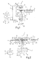
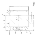
- Number 1 in the accompanying drawings indicates as a whole a unit for parting a sheet 2 of glass having, in the example shown, only one notch line as indicated by 3 in Figure 2.
- Unit 1 comprises a support 4 - in the example shown, a supporting table or a feed branch of a conveyor belt-defining a supporting surface 5 for sheet 2, an outer peripheral portion 2a of which projects from an outer peripheral edge 4a of support 4; and a parting device 6 separate from support 4 and comprising a powered frame 7 extending outside support 4.
- frame 7 is C-shaped with its concavity facing support 4, and is connected to a known powered actuating member 8, e.g.
- a controlled-axis manipulator or any other actuating device which forms part of unit 1 and provides for rotating frame 7 about a vertical axis 9 perpendicular to supporting surface 5, and for moving frame 7 along vertical axis 9 and around support 4 in a number of directions 10 lying in a plane parallel to supporting surface 5.
- Frame 7 comprises two arms 11 and 12 projecting facing each other on opposite sides of supporting surface 5 and peripheral portion 2a of sheet 2.
- Arm 11 is fitted integrally with a stop member 13, which is located, in use, astride an end portion 3a of notch line 3 extending across peripheral portion 2a, and is of a length L1, measured parallel to notch line 3, shorter than the length L of line 3 and, in particular, shorter than or at most equal to the length of end portion 3a.
- Stop member 13 extends, in use, outside a vertical plane P through edge 4a of support 4, and is defined, on the side facing portion 2a of sheet 2, by a concave surface 14 comprising two flat portions 15 converging with each other towards arm 11 ( Figure 2).
- arm 12 supports a pressure member 16 facing stop member 13 and positioned, in use, at and for exerting parting pressure on portion 3a.
- pressure member 16 is of a length L2, also measured parallel to notch line 3, equal to or less than the length of stop member 13; also extends outside plane P; and is connected integrally to the output rod 18 of a linear actuator, preferably a pneumatic or hydraulic jack 19, connected to arm 12 directly or, as in the example shown, via a powered guide-slide assembly 20 for adjusting the zero position of pressure member 16 as a function of the thickness S of sheet 2.
- Pressure member 16 is moved to and from stop member 13 - in the example shown, in a direction perpendicular to supporting surface 5 - according to a predetermined law of motion depending on the characteristics of sheet 2.
- jack 19 is controlled by a proportional solenoid valve 22, which is interposed between jack 19 and a known source (not shown) supplying a compressed fluid to jack 19, and is in turn controlled by a known central control unit 23 as a function of the thickness S of sheet 2 and the length L of notch line 3, which may be sent to central control unit 23 by known detecting devices (not shown) forming part of unit 1 or not, or may be stored in a memory 24 of central control unit 23 for storing such information relative to a number of differently sized and/or notched sheets for parting.
- central control unit 23 also controls powered member 8 and, hence, the movement of frame 7 along axis 9 and in directions 10.
- unit 1 Operation of unit 1 will now be described as of the condition in which the sheet 2 of glass is positioned on support 4 with portion 2a projecting from support 4, and pressure member 16 is in a lowered rest position separated from stop member 13 by a distance greater than thickness S of sheet 2.
- central control unit 23 first commands actuating member 8 to position stop member 13 astride portion 3a of notch line 3, and to position pressure member 16 at portion 3a, and then commands solenoid valve 22 to move pressure member 16 gradually towards sheet 2 and force portion 2a of sheet 2 against surface 14 so as to gradually part sheet 2 along notch line 3. Simultaneously with the movement of pressure member 16, central control unit 23 also raises actuating member 8 along axis 9 to lift sheet 2 gradually and partly off supporting surface 5.
- Lifting sheet 2 assists in guiding the break along notch line 3 and so reducing splintering and the likelihood of the break following a course other than the notch line.
- sheet 2 comprises further notch lines in addition to line 3
- central control unit 23 - which, in this case, knows the exact coordinates and length of each further notch line and the characteristics of the sheet portion obtained from the previous parting operation, because they are memorized beforehand and supplied to central control unit 23 - moves actuating member 8 in a plane parallel to supporting surface 5 so as to position stop and pressure members 13 and 16 at an end portion of the next notch line projecting from edge 4a, after which, the parting operations described above are repeated, and so on for each further notch line.
- unit 1 described therefore has the following advantages:
- support 4 is a straightforward support with a "clear" supporting surface, i.e. unhindered by fixed or, more importantly, transversely movable parting members, so that the sheet can be loaded easily and with no impediment on to the support either manually or by means of any handling device.
- parting members movable about the support and only acting on end portions of the notch lines provides for fast, accurate positioning of the parting members with respect to the notch line, and, above all, for positioning the parting members with no need to adjust the position of or move the sheet on the support, which is otherwise indispensable in the case of a sheet with a number of notch lines extending in different directions.
- the sheet need simply be placed on the support so that an end portion of each notch line projects from the edge of the support, after which, the sheet is parted successively by unit 1, which automatically moves about support 4 and automatically sets the parting members to the correct parting position.
Landscapes
- Chemical & Material Sciences (AREA)
- Engineering & Computer Science (AREA)
- Materials Engineering (AREA)
- Organic Chemistry (AREA)
- Securing Of Glass Panes Or The Like (AREA)
- Mirrors, Picture Frames, Photograph Stands, And Related Fastening Devices (AREA)
- Glass Compositions (AREA)
- Surface Treatment Of Glass (AREA)
Applications Claiming Priority (2)
| Application Number | Priority Date | Filing Date | Title |
|---|---|---|---|
| IT2000TO001011A IT1320824B1 (it) | 2000-10-24 | 2000-10-24 | Unita' per il troncaggio di una lastra di vetro incisa. |
| ITTO001011 | 2000-10-24 |
Publications (2)
| Publication Number | Publication Date |
|---|---|
| EP1201611A2 true EP1201611A2 (de) | 2002-05-02 |
| EP1201611A3 EP1201611A3 (de) | 2002-12-04 |
Family
ID=11458162
Family Applications (1)
| Application Number | Title | Priority Date | Filing Date |
|---|---|---|---|
| EP01125155A Withdrawn EP1201611A3 (de) | 2000-10-24 | 2001-10-23 | Vorrichtung zum Trennen eines geritzten Glastafels |
Country Status (2)
| Country | Link |
|---|---|
| EP (1) | EP1201611A3 (de) |
| IT (1) | IT1320824B1 (de) |
Cited By (1)
| Publication number | Priority date | Publication date | Assignee | Title |
|---|---|---|---|---|
| DE10205320A1 (de) * | 2002-02-08 | 2003-08-21 | Hegla Fahrzeug Und Maschb Gmbh | Verfahren und Vorrichtung zum Brechen von Glasplatten |
Family Cites Families (3)
| Publication number | Priority date | Publication date | Assignee | Title |
|---|---|---|---|---|
| US4595132A (en) * | 1983-11-01 | 1986-06-17 | Morton Glass Works | Device for fracturing glass along a scoreline |
| JPH06340439A (ja) * | 1993-05-26 | 1994-12-13 | Shigiya Seiki Seisakusho:Kk | 板ガラスの折割り装置とその関連装置 |
| IT1308409B1 (it) * | 1999-03-05 | 2001-12-17 | Bottero Spa | Metodo e macchina per la realizzazione di lastre di vetro sagomate. |
-
2000
- 2000-10-24 IT IT2000TO001011A patent/IT1320824B1/it active
-
2001
- 2001-10-23 EP EP01125155A patent/EP1201611A3/de not_active Withdrawn
Cited By (2)
| Publication number | Priority date | Publication date | Assignee | Title |
|---|---|---|---|---|
| DE10205320A1 (de) * | 2002-02-08 | 2003-08-21 | Hegla Fahrzeug Und Maschb Gmbh | Verfahren und Vorrichtung zum Brechen von Glasplatten |
| DE10205320B4 (de) * | 2002-02-08 | 2007-12-06 | Hegla Fahrzeug- Und Maschinenbau Gmbh & Co Kg | Verfahren zum Brechen von Glasplatten |
Also Published As
| Publication number | Publication date |
|---|---|
| EP1201611A3 (de) | 2002-12-04 |
| ITTO20001011A0 (it) | 2000-10-24 |
| IT1320824B1 (it) | 2003-12-10 |
| ITTO20001011A1 (it) | 2002-04-24 |
Similar Documents
| Publication | Publication Date | Title |
|---|---|---|
| US4971515A (en) | Apparatus for moving individual sheets from a stack of sheets | |
| US5457868A (en) | Work supporting method using a deck for use in machine tools, particularly in cutting machines | |
| EP1175957A1 (de) | Vacuum-Tisch-Vorrichtung zum Stützen und Halten einer Glasscheibe | |
| CN104822617B (zh) | 夹持表面定位系统 | |
| US4804173A (en) | Method and apparatus for moving individual sheets from a stack of sheets | |
| KR950005123B1 (ko) | 산업용 로봇의 복합기구손 | |
| JP3459796B2 (ja) | 単層又は多層のシート材を支持面上に保持するための装置及び方法 | |
| CA1257302A (en) | Pattern former/loader system for bakery products | |
| EP1201612A2 (de) | Vorrichtung zum trennen und handhaben von Glastafeln | |
| CN112693909B (zh) | 一种工业互联网用5g智能搬运机器人及使用系统 | |
| CN114901439A (zh) | 工件搬运系统 | |
| EP1201611A2 (de) | Vorrichtung zum Trennen eines geritzten Glastafels | |
| US6171045B1 (en) | Device for backing book blocks | |
| FI84715C (fi) | Foerfarande och anordning foer behandling av last. | |
| EP3257794B1 (de) | Glasverarbeitungstisch mit separaten lade- und verarbeitungsbereichen | |
| JPH07206158A (ja) | 物品移送装置 | |
| JP3788001B2 (ja) | コイル搬送用吊具及びその使用方法 | |
| JPS59193718A (ja) | プレスブレ−キにおける上下型の並行維持制御方法 | |
| JPH06206187A (ja) | 被搬送物挟持方法および装置 | |
| JP4045503B2 (ja) | 物品把持装置 | |
| EP1300352A2 (de) | Verfahren und Vorrichtung zum Aufgreifen von übereineanderliegenden Glastafeln | |
| EP3909900B1 (de) | Konstruktionsverfahren der greifausrüstung eines hebegeräts und mit einer solchen greifausrüstung verfügter hebegeräte | |
| CN106743566B (zh) | 转料装置 | |
| JP2535729B2 (ja) | ケ―スの移載方法及び移載装置 | |
| FI68596B (fi) | Foerfarande och anordning foer styrning av balanslyft |
Legal Events
| Date | Code | Title | Description |
|---|---|---|---|
| PUAI | Public reference made under article 153(3) epc to a published international application that has entered the european phase |
Free format text: ORIGINAL CODE: 0009012 |
|
| AK | Designated contracting states |
Kind code of ref document: A2 Designated state(s): AT BE CH CY DE DK ES FI FR GB GR IE IT LI LU MC NL PT SE TR |
|
| AX | Request for extension of the european patent |
Free format text: AL;LT;LV;MK;RO;SI |
|
| PUAL | Search report despatched |
Free format text: ORIGINAL CODE: 0009013 |
|
| AK | Designated contracting states |
Kind code of ref document: A3 Designated state(s): AT BE CH CY DE DK ES FI FR GB GR IE IT LI LU MC NL PT SE TR |
|
| AX | Request for extension of the european patent |
Free format text: AL;LT;LV;MK;RO;SI |
|
| 17P | Request for examination filed |
Effective date: 20030530 |
|
| AKX | Designation fees paid |
Designated state(s): AT BE CH CY DE DK ES FI FR GB GR IE IT LI LU MC NL PT SE TR |
|
| 17Q | First examination report despatched |
Effective date: 20031014 |
|
| STAA | Information on the status of an ep patent application or granted ep patent |
Free format text: STATUS: THE APPLICATION IS DEEMED TO BE WITHDRAWN |
|
| 18D | Application deemed to be withdrawn |
Effective date: 20040225 |