EP1203224B1 - Procede d'imagerie thermique avec reference synthetique - Google Patents
Procede d'imagerie thermique avec reference synthetique Download PDFInfo
- Publication number
- EP1203224B1 EP1203224B1 EP00939787A EP00939787A EP1203224B1 EP 1203224 B1 EP1203224 B1 EP 1203224B1 EP 00939787 A EP00939787 A EP 00939787A EP 00939787 A EP00939787 A EP 00939787A EP 1203224 B1 EP1203224 B1 EP 1203224B1
- Authority
- EP
- European Patent Office
- Prior art keywords
- pixel
- time
- image
- temperature
- data
- Prior art date
- Legal status (The legal status is an assumption and is not a legal conclusion. Google has not performed a legal analysis and makes no representation as to the accuracy of the status listed.)
- Expired - Lifetime
Links
- 238000000034 method Methods 0.000 title claims abstract description 34
- 238000001931 thermography Methods 0.000 title claims abstract description 24
- 230000001052 transient effect Effects 0.000 claims abstract description 21
- 238000004458 analytical method Methods 0.000 claims description 17
- 238000010438 heat treatment Methods 0.000 claims description 14
- 230000036962 time dependent Effects 0.000 claims 1
- 229910052751 metal Inorganic materials 0.000 description 20
- 239000002184 metal Substances 0.000 description 18
- 239000000463 material Substances 0.000 description 16
- 238000005259 measurement Methods 0.000 description 11
- 238000009499 grossing Methods 0.000 description 10
- 230000006870 function Effects 0.000 description 9
- 238000003384 imaging method Methods 0.000 description 9
- 230000002123 temporal effect Effects 0.000 description 7
- 238000013459 approach Methods 0.000 description 6
- 150000002739 metals Chemical class 0.000 description 6
- 230000003287 optical effect Effects 0.000 description 6
- 238000010304 firing Methods 0.000 description 5
- 230000008901 benefit Effects 0.000 description 4
- 230000000694 effects Effects 0.000 description 4
- 238000009659 non-destructive testing Methods 0.000 description 4
- 230000005855 radiation Effects 0.000 description 4
- 230000004044 response Effects 0.000 description 4
- 238000000576 coating method Methods 0.000 description 3
- 238000010586 diagram Methods 0.000 description 3
- 238000011156 evaluation Methods 0.000 description 3
- 238000005206 flow analysis Methods 0.000 description 3
- 229910052755 nonmetal Inorganic materials 0.000 description 3
- 230000008569 process Effects 0.000 description 3
- 238000012545 processing Methods 0.000 description 3
- 238000000926 separation method Methods 0.000 description 3
- 239000007787 solid Substances 0.000 description 3
- 238000012360 testing method Methods 0.000 description 3
- 230000008859 change Effects 0.000 description 2
- 239000011248 coating agent Substances 0.000 description 2
- 239000013078 crystal Substances 0.000 description 2
- 230000001419 dependent effect Effects 0.000 description 2
- 230000007246 mechanism Effects 0.000 description 2
- 150000002843 nonmetals Chemical class 0.000 description 2
- 239000005304 optical glass Substances 0.000 description 2
- 238000001454 recorded image Methods 0.000 description 2
- 238000005070 sampling Methods 0.000 description 2
- VYPSYNLAJGMNEJ-UHFFFAOYSA-N silicon dioxide Inorganic materials O=[Si]=O VYPSYNLAJGMNEJ-UHFFFAOYSA-N 0.000 description 2
- 230000001629 suppression Effects 0.000 description 2
- 229910000990 Ni alloy Inorganic materials 0.000 description 1
- 238000010521 absorption reaction Methods 0.000 description 1
- 230000004308 accommodation Effects 0.000 description 1
- 230000003466 anti-cipated effect Effects 0.000 description 1
- 230000009286 beneficial effect Effects 0.000 description 1
- 238000009529 body temperature measurement Methods 0.000 description 1
- 238000004891 communication Methods 0.000 description 1
- 239000002131 composite material Substances 0.000 description 1
- 238000007405 data analysis Methods 0.000 description 1
- 238000013500 data storage Methods 0.000 description 1
- 230000003247 decreasing effect Effects 0.000 description 1
- 230000004069 differentiation Effects 0.000 description 1
- 238000009792 diffusion process Methods 0.000 description 1
- 230000004907 flux Effects 0.000 description 1
- 239000011888 foil Substances 0.000 description 1
- 239000005350 fused silica glass Substances 0.000 description 1
- 238000007654 immersion Methods 0.000 description 1
- 230000006872 improvement Effects 0.000 description 1
- 239000007788 liquid Substances 0.000 description 1
- 238000013507 mapping Methods 0.000 description 1
- 238000000691 measurement method Methods 0.000 description 1
- 239000002905 metal composite material Substances 0.000 description 1
- 238000012986 modification Methods 0.000 description 1
- 230000004048 modification Effects 0.000 description 1
- 230000002093 peripheral effect Effects 0.000 description 1
- 239000010453 quartz Substances 0.000 description 1
- 230000000191 radiation effect Effects 0.000 description 1
- 238000012552 review Methods 0.000 description 1
- 230000000007 visual effect Effects 0.000 description 1
- 239000011800 void material Substances 0.000 description 1
Images


Classifications
-
- G—PHYSICS
- G01—MEASURING; TESTING
- G01B—MEASURING LENGTH, THICKNESS OR SIMILAR LINEAR DIMENSIONS; MEASURING ANGLES; MEASURING AREAS; MEASURING IRREGULARITIES OF SURFACES OR CONTOURS
- G01B21/00—Measuring arrangements or details thereof, where the measuring technique is not covered by the other groups of this subclass, unspecified or not relevant
- G01B21/02—Measuring arrangements or details thereof, where the measuring technique is not covered by the other groups of this subclass, unspecified or not relevant for measuring length, width, or thickness
- G01B21/08—Measuring arrangements or details thereof, where the measuring technique is not covered by the other groups of this subclass, unspecified or not relevant for measuring length, width, or thickness for measuring thickness
- G01B21/085—Measuring arrangements or details thereof, where the measuring technique is not covered by the other groups of this subclass, unspecified or not relevant for measuring length, width, or thickness for measuring thickness using thermal means
-
- G—PHYSICS
- G01—MEASURING; TESTING
- G01N—INVESTIGATING OR ANALYSING MATERIALS BY DETERMINING THEIR CHEMICAL OR PHYSICAL PROPERTIES
- G01N25/00—Investigating or analyzing materials by the use of thermal means
- G01N25/72—Investigating presence of flaws
-
- G—PHYSICS
- G01—MEASURING; TESTING
- G01B—MEASURING LENGTH, THICKNESS OR SIMILAR LINEAR DIMENSIONS; MEASURING ANGLES; MEASURING AREAS; MEASURING IRREGULARITIES OF SURFACES OR CONTOURS
- G01B11/00—Measuring arrangements characterised by the use of optical techniques
- G01B11/02—Measuring arrangements characterised by the use of optical techniques for measuring length, width or thickness
- G01B11/06—Measuring arrangements characterised by the use of optical techniques for measuring length, width or thickness for measuring thickness ; e.g. of sheet material
Definitions
- the present invention relates to thermographic nondestructive testing techniques for determining the thickness of an object. More particularly, the present invention relates to a infrared transient thermography method that utilizes a synthetic thermal reference in determining the wall thickness of metal turbine rotor blades or the like.
- infrared (IR) transient thermography is a somewhat more versatile nondestructive testing technique that relies upon temporal measurements of heat transference through an object to provide information concerning the structure and integrity of the object. Since heat flow through an object is substantially unaffected by the micro-structure and the single-crystal orientations of the material of the object, an infrared transient thermography analysis is essentially free of the limitations this creates for ultrasonic measurements. In contrast to most ultrasonic techniques, a transient thermographic analysis approach is not significantly hampered by the size, contour or shape of the object being tested and, moreover, can be accomplished ten to one-hundred times faster than most conventional ultrasonic methods if testing objects of large surface area.
- the size and a value indicative of a "relative" depth of a flaw can be determined based upon a careful analysis of the temperature changes occurring at each resolution element over the surface of the object.
- the "actual" depth of a flaw i. e., the depth of a flaw from the surface of the object
- a "standards block" having voids at known depths, or an "infinite" (thermally thick) reference region on the object is included as part of the thermographic data acquisition and analysis for comparison against the relative depth values.
- the surface of an object must be heated to a particular temperature in a sufficiently short period of time so as to preclude any significant heating of the remainder of the object.
- a quartz lamp or a high intensity flash-lamp is conventionally used to generate a heat pulse of the proper magnitude and duration.
- the specific mechanism used to heat the object surface could be any means capable of quickly heating the surface to a temperature sufficient to permit thermographic monitoring-such as, for example, pulsed laser light.
- an infrared (IR) video camera has been used to record and store successive thermal images (frames) of an object surface after heating it.
- Each video image is composed of a fixed number of pixels.
- a pixel is a small picture element in an image array or frame which corresponds to a rectangular area, called a "resolution element", on the surface of the object being imaged. Since, the temperature at each resolution element is directly related to the intensity of the corresponding pixel, temperature changes at each resolution element on the object surface can be analyzed in terms of changes in pixel contrast.
- the stored IR video images are used to determine the contrast of each pixel in an image frame by subtracting the mean pixel intensity for a particular image frame, representing a known point in time, from the individual pixel intensity at that same point in time.
- the contrast data for each pixel is then analyzed in the time domain (i.e., over many image frames) to identify the time of occurrence of an "inflection point" of the contrast curve data, which is mathematically related to a relative depth of a flaw within the object.
- a heat flux pulse impinging on an object takes a certain "characteristic time", T c , to penetrate through the object to the opposite side (back wall) and return to the front surface being imaged.
- T-t characteristic time
- T c characteristic time
- Equ. (2) This relationship between the inflection point and the characteristic time, as expressed by Equ. (2) above, is precise to approximately 1% for one-dimensional (1-D), as well as two-dimensional (2-D), heat flow analysis.
- a slab object of similar material having portions of known thickness is used as a "infinite half-space" reference standard within the same image frame (a "thermally thick” section of the examined object may optionally be used as the reference).
- the flash-lamp are fitted with spectrally tuned optical filters that minimize long-wave IR "afterglow” emissions and reduce background radiation effects which affect the accuracy of thermal measurements.
- a predetermined number of IR image frames are acquired and recorded over a predetermined period of time after firing the flash-lamps to develop a temperature-time (T-t) history of the object surface (and the reference standard). Contrast verses time data is then developed for each pixel in the image to determine object thickness at a location corresponding to the pixel position.
- contrast-time data is developed by subtracting temperature-time data of the slab reference standard (or temperature-time data of a "deep" thermally thick reference region on the object) from the temperature-time data of each pixel.
- this method suffers from the disadvantage that it may introduce some degree of error when imaging objects that have varying surface uniformity.
- it requires the presence of a slab standard in the image or the use of temperature-time data from a deep reference region on the object-assuming such a reference region is available.
- a special coating must usually be applied to the surface of the object (and the slab standard) prior to imaging to enhance optical absorption and improve surface uniformity.
- the present invention relates to a nondestructive testing method and apparatus for determining and displaying the actual thickness of an object through the use of high speed infrared (IR) transient thermography.
- An improved high-speed IR transient thermography analysis approach is utilized to accurately measure the thickness of an object and provide a visual coded display indicative of its cross-sectional thickness over a desired area of the object.
- a salient feature of the present invention is that a "synthetic" or computed reference, based on actual surface temperature, is used to compute the contrast verses time data needed to determine thickness. Consequently, at least one beneficial aspect of the present invention is that it does not require the use of a separate reference standard or a reference region on the examined object.
- the transient thermographic technique of the present invention there is no need to apply special coatings to the object (s) being examined.
- the method of the present invention can readily accommodate objects having non-uniform surfaces or varying surface emissivity.
- the present invention makes use of an inflection point in a temperature-time (T-t) response analysis of the surface of a rapidly heated object, preferably obtained from "front-side" IR camera observations.
- This inflection point, t infl occurs relatively early in the T-t response and is essentially independent of lateral heat loss mechanisms. (Such considerations may be of particular relevance, for example, when working with metals since, due to the high thermal conductivity of metals, the thermal response of a metal object is fairly quick and, consequently, the time available for obtaining thermal data measurements is usually short).
- the inflection point, t infl is extracted from thermal data acquired over a predetermined time period from successive IR camera image frames.
- this time period is at least somewhat longer than an anticipated characteristic time, as obtained from Equ. (1), based on an estimation of the thickness of the object being evaluated.
- the inflection point, t jnfl is determined by utilizing pixel contrast data that is based on a "synthetic" or computed thermal reference instead of a "real" reference such as a slab standard or a suitable region on the examined object.
- T s t A ⁇ t 1 / 2 - ( t - ⁇ ⁇ ) 1 / 2
- A is a parameter selected to match actual surface temperature on an object surface at a location corresponding to a selected analysis pixel in an acquired IR image, and is a duration of heating the object before acquiring image frames.
- Equ. (3) describes a "synthetic" half-space thermal decay based on an initial temperature, A, at a particular location on the surface of the object.
- the "synthetic" thermal reference data as obtained from Equ. (3) is first computed for each (x, y) pixel location of the imaged object and then used to determine contrast as a function of time for each pixel.
- determination of the synthetic thermal reference data is not dependent upon the nature or characteristic of the particular material or metal being evaluated-as it is not a parameter in Equ. (3).
- the apparatus includes an imaging system comprising one or more high power flash lamps fitted with special optical filters, an IR sensitive focal-plane array camera for data acquisition and a display monitor.
- a computer system controls the imaging system, records and analyzes surface temperature data acquired via the IR camera and provides a color or gray pattern-keyed image on the display monitor that accurately corresponds to thickness of the object
- the acquisition of surface temperature data is initiated by firing the flash-lamps to illuminate the surface of the object.
- the special optical filters are spectrally tuned to absorb and/or reflect all 3-5 micron IR radiation back into the flash-lamp(s). This prevents undesirable long-wave IR "afterglow” emissions-typicatty generated by overheated metallic elements in the flash-lamps after the lamps are extinguished-from reaching the object or the camera.
- the use of such filters enables a more precise thermal evaluation that can produce dimensional measurements within an accuracy range of 1%-3% of actual thickness.
- a predetermined number of image frames are then recorded over a period of time after the flash lamps are fired and the recorded images used to develop a temperature-time (T-t) history for every elemental region or "resolution element" over the region of interest on the object surface.
- Each recorded image frame is comprised of a predetermined n x m array of image pixels whose intensity correlate to the surface temperature of the object at the time the frame data was acquired-each pixel having an (x,y) location designation within the image frame that corresponds to a particular resolution element.
- T c characteristic time
- a value for characteristic time T c may be determined by using a recorded intensity-verses-time history of the pixel to compute contrast-verses-time data for the pixel-which in the present invention is accomplished by subtracting the "synthetic" thermal reference T-t data from the recorded intensity-verses-time data of the pixel.
- a contrast-verse-time curve is determined for each (x,y) pixel location corresponding to each resolution element of the object surface.
- Gaussian temporal smoothing of the pixel contrast curve data is employed to improve the signal-to-noise ratio of the measurements.
- the mathematical derivative of the contrast curve is then computed to identify an inflection point in the data. This derivative is preferably computed using a three-point data sampling having a first and third sample point separation that is proportionally related to the value of the image frame number at the second sample point.
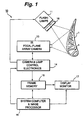
- FIGURE 1 illustrates an example IR transient thermography system 10 for determining and displaying the thickness of an object, e.g., a metal turbine airfoil 1 having intentional voids 4.
- an object e.g., a metal turbine airfoil 1 having intentional voids 4.
- the "thickness" of an object refers to a front wall or surface thickness in the context of a hollow or semi-hollow object (i.e., an object having an intentional void).
- a flash-lamp heat-pulse source 11 is used to rapidly heat the surface of the object being measured.
- One suitable arrangement for flash-lamp heat-pulse source 11 would be, for example, a set of four or eight high-speed, high output power photographic flash-lamps, each capable of about 4.8 Kilo-joules output and having individual power supplies (such as, for example, flash-lamps manufactured by Speedotron, Corp. in Chicago, IL).
- one or more filters may be used (e.g., one per each flash-lamp). These filters act to prevent direct long wave radiation-typically generated from the "afterglow” of overheated metallic elements in the flash-lamps-from ever leaving the flash-lamps and impinging on the target or otherwise reflecting back into focal-plane array camera 13. Such primary afterglow radiation from flash-lamps 11 competes and can interfere with the long-wave IR emissions from the targeted object during early thermal data acquisition, thus obscuring the true target-generated IR radiation and reducing ultimate image contrast and quality. Thus, the use of these special filters produces a sufficiently sharp heat pulse to enable the shorter heat travel time in metal to be detected.
- flash-lamp filter 18 may be composed of PyrexTM, fused quartz, BK7TM, or other optical material that is transparent to visible and UV light and is coated on the flash-lamp facing side with an infrared-reflective coating to reflect all radiation in the 3-5 micron range back into the flash-lamps.
- Optical glass and coated filters may be acquired or specially manufactured by a general scientific optics and optical glass manufacturer such as, for example, Oriel in Stratford, CT.).
- IR sensitive imaging system comprising an IR sensitive focal-plane array camera 13 (e.g., a Radiance HS camera may be available from Amber Engineering in Goleta, Ca.-a Raytheon Company), control electronics 14, frame data memory 15, control computer/image processor 16 and display monitor 17.
- IR sensitive focal-plane array camera 13 e.g., a Radiance HS camera may be available from Amber Engineering in Goleta, Ca.-a Raytheon Company
- Flash-lamp firing is controlled via conventional flash-lamp electronics 14 managed by conventional video frame acquisition software running on system computer 16 (such as provided by the ImageDeskTM frame acquisition system from Amber Corp. or other conventional frame acquisition and flash-lamp control software, for example, such as commercially available from Thermal Wave Imaging Inc. in Lathrup Village, MI).
- system computer 16 such as provided by the ImageDeskTM frame acquisition system from Amber Corp. or other conventional frame acquisition and flash-lamp control software, for example, such as commercially available from Thermal Wave Imaging Inc. in Lathrup Village, MI).
- the system control computer/image processor 16 is a specially programmed general purpose digital computer that is capable of peripheral equipment control and communication functions in addition to digital image processing and display in accordance with the method of the present invention.
- System computer 16 controls camera and lamp electronics 14 and frame data memory 15 to acquire a predetermined number of successive thermal image frames of the object surface which are stored in memory 15 for future analysis.
- IR camera 13 is first calibrated using a "full-field" dual-image calibration technique as now described.
- This preferred technique employs two “black-body” (BB) image calibration references: a BB “cold” source using a room-temperature flat-black plate and a BB “hot” source using a heated flat-black plate.
- BB black-body
- a flat-black painted box enclosing the room-temperature flat-black plate, arranged at a 45° angle to the camera lens, is placed directly in front of the lens.
- the camera lens For acquiring the BB "hot” source calibration image, the camera lens is placed into the same flat-black painted box unit after heating the flat-black plate-nominally to about 10° C above ambient-such that the camera images the heated plate over its full field.
- the above described dual-image calibration technique is preferred, any calibration technique that results in producing maximum uniformity of the image field-which is important for high contrast imaging and obtaining improved thermal accuracy-can be used.
- Each image frame acquired during the imaging process consists of NxN pixels-each pixel corresponding to a resolution element on the object surface-where N is typically either 128 or 256 depending on the resolution and accuracy desired.
- N is typically either 128 or 256 depending on the resolution and accuracy desired.
- Each pixel occupies about two bytes of storage memory and may be represented, for example, by a 12-bit or larger binary number.
- the stored image frames are sequentially identified with increasing frame number values which together serve to provide a historical record of the temperature vs. time (T-t) characteristics of a front surface of object 1 for a predetermined period after being struck by the heat impulse imparted by flash lamp 11.
- image data frames are acquired from camera 13 and the IR intensity at each resolution element on the image is digitally recorded and stored in frame data recorder 15.
- Data acquisition continues over a predetermined number of sequential image frames that are sufficient to acquire a meaningful T-t history over a duration of at least one estimated "characteristic time" for the material of the object.
- the total number of image frames acquired may vary depending on the accuracy and image resolution desired and can be as high as 550 frames per second of data acquisition.
- Frame data recorder 15 may be a conventional digital memory internal to processor 16 or any suitable video frame data storage device accessible by processor 16. Each successive thermal image frame acquired is assigned an increasing frame number, Z, corresponding to the passage of real time.
- the resulting data frame "stack" is then analyzed taking a one-dimensional heat flow analysis approach, as outlined above.
- the method of the present invention takes advantage of a known thermal invariance property-evidenced in the temperature vs. time (T-t) history of each image pixel over successive IR image frames-that relies on identifying the location of an inflection point" or peak slope time, i.e., the point in time of maximum slope on the T-t data curve.
- FIGURE 2 a flow diagram is presented that illustrates example processing steps for conducting transient IR thermography using synthetic-reference thermal imaging techniques of the present invention. These steps may be implemented, for example, by appropriately programming computer 16 ( Fig. 1 ) using known conventional programming techniques.
- a region of interest on the object is identified (i.e., the IR camera is focused to capture the region of interest) and the system operator selects or inputs information concerning relevant parameters for examining the object such as, for example, a thermal diffusivity coefficient for the material.
- the system control computer instructs the flash-lamp electronics to fire flash-lamps 11 and initiate image frame data acquisition from the focal plane array IR camera 13. Data acquisition proceeds over a predetermined number of sequential image frames and then, as indicated at 21, the image sequence is stored in frame memory 15 after identifying each acquired image frame with a sequential frame number, Z.
- a set of T-t curve data is identified for each pixel in the thermal image corresponding to each resolution element location over the region of interest on the surface of the object. Also, a time and frame number of the initial IR "flash” heating is identified, a first unsaturated data frame is identified, and a "synthetic" half-space thermal decay T-t reference data curve ( refcurve ) is generated based upon an initial surface temperature parameter, A, and the flash duration, ⁇ , according to Equ (3) as given above.
- Equ. (3) is valid for times (t) greater than or equal to (the flash heating duration).
- the parameter A is chosen to match the actual initial value of temperature as measured at a selected analysis pixel in the image.
- the starting temperature for a synthetic thermal decay reference, thus generated is rendered adjustable at each pixel without having to know the nature of the particular material being examined.
- the generated synthetic reference of the present invention can accommodate such variations; whereas, a "real" slab standard thermal reference can not, since it is limited to a fixed-value starting temperature.
- a first pixel (or the next pixel) is then selected for analysis and its T-t curve data ( ttcurve ) is developed from recorded pixel intensity data stored in frame memory 15.
- T-t curve data ( ttcurve ) is developed from recorded pixel intensity data stored in frame memory 15.
- optional offset and scale (amplitude) adjustments can also be made at this step to help compensate for any derogatory effects such as, for example, loss of amplitude due to surface curvatures.
- a contrast curve ( concurve ) is determined for the selected pixel by subtracting the synthetic reference T-t curve data ( refcurve ) from the T-t curve ( ttcurve ) data of the pixel.
- a Gaussian function temporal smoothing of the contrast curve data may also be performed.
- a "temporal window" used in the Gaussian smoothing algorithm is made to vary as a function of time by making it proportional to the image frame number, Z, corresponding to the contrast data. Essentially, this smoothing "window” controls the full-width of the Gaussian at half-maximum (i.e., the "2- ⁇ " width).
- Using a variable-width frame-number smoothing as described is more advantageous than a traditional Gaussian smoothing because it tends to compensate for the effects of heat diffusion at increasing depths within the material.
- the width of the smoothing window at a selected data point is made proportional to the square-root of the image frame number at that point.
- a number of software implemented "imaging filters" may also be applied to the contrast curve data at this stage, including spatial smoothing, initial and ending noise suppression, negative contrast suppression and contrast thresholding.
- the mathematical derivative of the contrast curve, indicative of the inflection point is determined. It is well known that the point of maximum slope on a curve can be determined by using a conventional 3-consecutive-point derivative algorithm in which three equally spaced consecutive data points along the curve are sampled and used to calculate the slope of the curve at the second (middle) data point. In accordance with the present invention, three points are still used to determine the derivative of the contrast curve, but the separation of the first and third sample derivative points (i.e., the width of the derivative base interval) is linked to real time in the image evolution via the image frame number. Specifically, the width of the derivative base interval at any selected point along the contrast curve is made proportional to the square-root of the IR image frame number, Z.
- the signal-to-noise (S/N) characteristics are maximized even in the midst of high noise levels.
- This improvement in the S/N ratio results from "sampling" over a larger interval and, thus, detects the largest signal change rather than the differential change traditionally obtained with fixed-width 3-point differentiation. Since a maximum S/N ratio is obtained when the sample point separation is equal to the full Gaussian width, the maximum possible S/N ratio is always achieved by using the frame-number proportional-width approach of the present invention.
- step 28 all local peaks in the derivative curve are identified and a significance "weighting" factor is used to assess the proper peak to use as the t infl inflection point.
- a list of all peak location times (i.e., frame numbers) and amplitudes is maintained in computer memory.
- By applying a predetermined appropriate weighting function to the peak list it is possible to adjust the significance of each peak so that, for example, peak-producing noise effects arising early in the data acquisition time are effectively discounted. Since empirical evidence indicates that peaks occurring later in time tend to be more significant, a temporal weighting function is implemented in the present example embodiment by simply multiplying the amplitude of a peak by the time at which it occurred. The peaks are then sorted according to decreasing significance (weight) and the peak having the greatest weighting value (i.e., the most significant) is selected as indicative of the proper inflection point.
- the thickness of the object at the location of the resolution element corresponding to the selected pixel is determined. This is accomplished by identifying the frame number in which the most significant peak occurs, i.e., the inflection point t infl , and converting that value to real time. Since acquisition of IR image frames occurs at a fixed predetermined rate, a frame number can be equated to a real elapsed time. Accordingly, the frame number of the IR image frame harboring the most significant peak in the derivative curve provides an actual quantitative time value for t infl . Using this value for t infl in Equ. (1) and Equ. (2) above, provides a thickness value, L, denoting the actual thickness of the object at the location of the resolution element corresponding to the analyzed pixel.
- the thickness value, L is stored in memory and used to build a color-mapped or gray-scale image of the region of interest on the object surface for display or print-each color or gray shade corresponding to a particular thickness.
- the next pixel is then selected, as indicated at 23, and the above steps are reiterated for each pixel comprising the IR image.
- wall thickness values can be accurately obtained even between closely spaced back wall or internal structures that may form a part of, or be connected to, the tested object-e.g., the rib-like structures often found in turbine air foils (as depicted in FIGURE 1 )-whereas using traditional thermal or ultrasonic methods such closely positioned back-wall structures would normally result in blurred images and distorted data.
- FIGURE 3 a diagram of an infrared transient thermography display image for a multi-tiered object block is depicted.
- Object block 31 depicted in FIGURE 3 has six square sections of different thickness. The thickness of each of the six sections is indicated by a different color or gray tone in the generated image (shown here as different cross-hatchings) which corresponds to a like color or shade in a bar-scale thickness key displayed at the right of the image.
- the bar-scale includes indicia of thickness ranging from 0.033 to 0.142 cm (0.013 to 0.056 inches), but a displayed bar-scale having a different range may also be used.
Landscapes
- General Physics & Mathematics (AREA)
- Physics & Mathematics (AREA)
- Immunology (AREA)
- Chemical & Material Sciences (AREA)
- Analytical Chemistry (AREA)
- Biochemistry (AREA)
- General Health & Medical Sciences (AREA)
- Life Sciences & Earth Sciences (AREA)
- Health & Medical Sciences (AREA)
- Pathology (AREA)
- Radiation Pyrometers (AREA)
- Investigating Or Analyzing Materials Using Thermal Means (AREA)
- Closed-Circuit Television Systems (AREA)
- Length Measuring Devices With Unspecified Measuring Means (AREA)
- Image Processing (AREA)
- Transforming Light Signals Into Electric Signals (AREA)
- Thermal Transfer Or Thermal Recording In General (AREA)
- Heating, Cooling, Or Curing Plastics Or The Like In General (AREA)
- Heat Sensitive Colour Forming Recording (AREA)
Claims (4)
- Procédé de thermographie infrarouge (LR) en régime transitoire permettant de déterminer l'épaisseur d'un objet ayant une surface qui peut être visualisée sous la forme d'une matrice de pixels, comprenant les étapes consistant à:(a) chauffer rapidement la surface de l'objet;(b) enregistrer une intensité de pixel d'une séquence d'images IR, chaque image ayant un numéro d'image séquentielle attribué (Z) lié au temps écoulé depuis le chauffage de la surface de l'objet à l'étape (a);
caractérisé par les étapes consistant à:(c) déterminer des données de contraste de pixel d'après au moins l'intensité de pixel et une courbe de référence température-temps, Ts(t), calculée selon l'équation mathématique suivante:
dans laquelle A est la température initiale à un endroit particulier sur la surface de l'objet et est choisie pour concorder avec la température réelle sur la surface de l'objet à un endroit correspondant à un pixel d'analyse choisi dans une image IR acquise, τ est une durée de chauffage de l'objet avant l'acquisition d'images et t est le temps; et(d) déterminer l'épaisseur de l'objet d'après au moins le contraste de pixel déterminé à l'étape (c) et le numéro d'image (Z) attribué à l'étape (b). - Procédé selon la revendication 1, comprenant en outre l'étape de mesure d'une température sur la surface de l'objet correspondant audit pixel d'analyse choisi.
- Procédé selon la revendication 1, dans lequel l'objet est chauffé en utilisant un dispositif à lampe flash.
- Procédé selon la revendication 1, comprenant en outre le fait d'utiliser une caméra à matrice à plan focal sensible à l'IR pour acquérir des données d'intensité de pixel à partir de la séquence d'images IR de l'objet, chaque image comprenant une pluralité de pixels; et dans lequel
ladite courbe de référence température-temps, Ts(t), est calculée à partir d'un modèle mathématique de référence thermique représentant un flux de chaleur monodimensionnel dans un milieu semi-infini; et dans lequel
lesdites données de contraste de pixel sont déterminées en soustrayant ladite courbe de référence température-temps de données d'intensité de pixel acquises afin de développer des données de contraste température-temps pour au moins un pixel; et dans lequel
l'épaisseur réelle au niveau d'un élément de résolution de l'objet correspondant au pixel est déterminée en utilisant lesdites données de contraste, ladite détermination étant basée sur une relation d'invariance du flux de chaleur entre un point d'inflexion dans les données de contraste et un temps caractéristique du flux de chaleur qui dépend de la diffusivité thermique de l'objet.
Applications Claiming Priority (5)
| Application Number | Priority Date | Filing Date | Title |
|---|---|---|---|
| US14488699P | 1999-07-21 | 1999-07-21 | |
| US144886P | 1999-07-21 | ||
| US568053 | 2000-05-10 | ||
| US09/568,053 US6367969B1 (en) | 1999-07-21 | 2000-05-10 | Synthetic reference thermal imaging method |
| PCT/US2000/016053 WO2001007902A1 (fr) | 1999-07-21 | 2000-06-12 | Procede d'imagerie thermique a coordonnees synthetiques |
Publications (2)
| Publication Number | Publication Date |
|---|---|
| EP1203224A1 EP1203224A1 (fr) | 2002-05-08 |
| EP1203224B1 true EP1203224B1 (fr) | 2008-07-09 |
Family
ID=26842457
Family Applications (1)
| Application Number | Title | Priority Date | Filing Date |
|---|---|---|---|
| EP00939787A Expired - Lifetime EP1203224B1 (fr) | 1999-07-21 | 2000-06-12 | Procede d'imagerie thermique avec reference synthetique |
Country Status (9)
| Country | Link |
|---|---|
| US (1) | US6367969B1 (fr) |
| EP (1) | EP1203224B1 (fr) |
| JP (1) | JP4698907B2 (fr) |
| KR (1) | KR100720214B1 (fr) |
| AT (1) | ATE400808T1 (fr) |
| BR (1) | BR0012679A (fr) |
| DE (1) | DE60039433D1 (fr) |
| TR (1) | TR200200139T2 (fr) |
| WO (1) | WO2001007902A1 (fr) |
Cited By (4)
| Publication number | Priority date | Publication date | Assignee | Title |
|---|---|---|---|---|
| US8197129B2 (en) | 2006-09-15 | 2012-06-12 | Siemens Aktiengesellschaft | Method and apparatus for determining component parameters by means of thermography |
| WO2013083846A1 (fr) | 2011-12-10 | 2013-06-13 | Thermosensorik Gmbh | Procédé d'étude d'un échantillon au moyen de la thermographie à flux de chaleur |
| EP2743688A1 (fr) | 2012-12-17 | 2014-06-18 | Thermosensorik Gmbh | Procédé et système pour l'examen d'un échantillon par thermographie |
| CN109030546A (zh) * | 2018-07-23 | 2018-12-18 | 清华大学 | 高温变形和温度测量系统和方法 |
Families Citing this family (39)
| Publication number | Priority date | Publication date | Assignee | Title |
|---|---|---|---|---|
| WO2001041421A2 (fr) * | 1999-12-02 | 2001-06-07 | Thermal Wave Imaging, Inc. | Procede et systeme thermographique de detection sans reference de defauts de sous-surfaces au moyen de donnees d'images comprimees |
| US6517238B2 (en) * | 2001-01-18 | 2003-02-11 | The United States Of America As Represented By The United States Department Of Energy | Thermal imaging measurement of lateral diffusivity and non-invasive material defect detection |
| ITRM20020023A1 (it) * | 2002-01-18 | 2003-07-18 | Intelligence Devices S R L | Metodo e relativo dispositivo per il rilevamento di oggetti. |
| US6712502B2 (en) * | 2002-04-10 | 2004-03-30 | The United States Of America As Represented By The Administrator Of The National Aeronautics And Space Administration | Synchronized electronic shutter system and method for thermal nondestructive evaluation |
| US7064331B2 (en) * | 2002-09-13 | 2006-06-20 | Siemens Power Generation, Inc. | Method for calibrating and enhancing flaw detection of an acoustic thermography system |
| US7071462B2 (en) * | 2003-06-16 | 2006-07-04 | Raytek Corporation | Calibration system and method to correct distortion of thermal images from in-line and rotary thermoforming machines |
| US20050018748A1 (en) * | 2003-07-24 | 2005-01-27 | Ringermacher Harry Israel | Actively quenched lamp, infrared thermography imaging system, and method for actively controlling flash duration |
| US7015473B2 (en) * | 2003-09-30 | 2006-03-21 | General Electric Company | Method and apparatus for internal feature reconstruction |
| JP4672313B2 (ja) * | 2004-09-01 | 2011-04-20 | アンリツ株式会社 | 印刷はんだ検査装置 |
| CN100383502C (zh) * | 2004-12-17 | 2008-04-23 | 华中科技大学 | 红外序列图像历史趋势分析方法 |
| US7591583B2 (en) * | 2005-05-18 | 2009-09-22 | Federal-Mogul World Wide, Inc. | Transient defect detection algorithm |
| US7388204B2 (en) * | 2005-12-07 | 2008-06-17 | Meyer Tool, Inc. | Apparatus and method for analyzing relative outward flow characterizations of fabricated features |
| US7409313B2 (en) * | 2005-12-16 | 2008-08-05 | General Electric Company | Method and apparatus for nondestructive evaluation of insulative coating |
| US7822268B2 (en) * | 2006-06-06 | 2010-10-26 | Siemens Energy, Inc. | Advanced processing of active thermography signals |
| US7671338B2 (en) * | 2006-06-14 | 2010-03-02 | Meyer Tool, Inc. | Apparatus and method for analyzing relative outward flow characterizations of fabricated features |
| US7365330B1 (en) * | 2006-09-18 | 2008-04-29 | Uchicago Argonne, Llc | Method for thermal tomography of thermal effusivity from pulsed thermal imaging |
| DE102006044443A1 (de) * | 2006-09-21 | 2008-04-03 | Robert Bosch Gmbh | Automatische Erkennung von Beschichtungsfehlern |
| US7516663B2 (en) * | 2006-11-03 | 2009-04-14 | General Electric Company | Systems and method for locating failure events in samples under load |
| US7966883B2 (en) * | 2006-12-06 | 2011-06-28 | Lockheed Martin Corporation | Non-destructive inspection using laser-ultrasound and infrared thermography |
| US7605924B2 (en) | 2006-12-06 | 2009-10-20 | Lockheed Martin Corporation | Laser-ultrasound inspection using infrared thermography |
| US7549789B2 (en) * | 2007-06-20 | 2009-06-23 | General Electric Company | Method and apparatus for thermographic nondestructive evaluation of an object |
| CN100498806C (zh) * | 2007-09-19 | 2009-06-10 | 中国科学院上海技术物理研究所 | 仿真红外探测器输出信号的装置及方法 |
| JP5307155B2 (ja) * | 2007-12-06 | 2013-10-02 | ロッキード マーティン コーポレイション | レーザ超音波及び赤外線サーモグラフィを使用する非破壊検査 |
| US8393784B2 (en) * | 2008-03-31 | 2013-03-12 | General Electric Company | Characterization of flaws in composites identified by thermography |
| US8384783B2 (en) | 2009-09-29 | 2013-02-26 | Flir Systems Ab | Infrared camera and method for calculating output power value indicative of an amount of energy dissipated in an image view |
| US8692887B2 (en) * | 2010-08-27 | 2014-04-08 | General Electric Company | Thermal imaging method and apparatus for evaluating coatings |
| US9007466B2 (en) * | 2011-04-27 | 2015-04-14 | General Electric Company | System and method for thermographic inspection |
| US8958058B2 (en) * | 2011-11-15 | 2015-02-17 | Process Metrix | Apparatus, process, and system for monitoring the integrity of containers |
| US9500611B2 (en) | 2013-09-26 | 2016-11-22 | General Electric Company | Lamp assembly for a thermographic nondestructive evaluation system |
| US9250136B1 (en) | 2014-08-29 | 2016-02-02 | General Electric Company | Hyperspectral imaging system for pyrometry applications and method of operating the same |
| RU2590347C1 (ru) * | 2015-04-01 | 2016-07-10 | Федеральное государственное автономное образовательное учреждение высшего образования "Национальный исследовательский Томский политехнический университет" | Способ бесконтактного одностороннего активного теплового неразрушающего контроля |
| US10830132B2 (en) | 2016-04-29 | 2020-11-10 | General Electric Company | Micro thermal imaging system for turbine engines |
| CN107782764B (zh) * | 2016-08-25 | 2021-02-23 | 成都鼎桥通信技术有限公司 | 一种光伏组件的故障识别方法 |
| CN106351803B (zh) * | 2016-11-02 | 2019-02-26 | 广州特种承压设备检测研究院 | 海上风力机叶片运行状态监测系统 |
| US11397112B2 (en) | 2017-01-09 | 2022-07-26 | General Electric Company | System and method for monitoring of gas turbine components with infrared system |
| US11193820B2 (en) | 2017-01-09 | 2021-12-07 | General Electric Company | System and method for disposable infrared imaging system |
| US10241036B2 (en) * | 2017-05-08 | 2019-03-26 | Siemens Energy, Inc. | Laser thermography |
| CN108490030B (zh) * | 2018-03-30 | 2021-03-23 | 吉林建筑大学 | 基于无人机红外热成像的建筑围护结构热工性能检测方法 |
| CN116818827B (zh) * | 2023-06-29 | 2026-01-09 | 中国联合网络通信集团有限公司 | 热扩散系数的获取方法、装置及存储介质 |
Family Cites Families (22)
| Publication number | Priority date | Publication date | Assignee | Title |
|---|---|---|---|---|
| US4854724A (en) | 1984-07-09 | 1989-08-08 | Lockheed Corporation | Method of and apparatus for thermographic evaluation of spot welds |
| GB8431928D0 (en) | 1984-12-18 | 1985-01-30 | Stevenson G M | Non-destructively testing heat shrinkable sleeves |
| JPS62172249A (ja) | 1986-01-25 | 1987-07-29 | Kajima Corp | 煙突の劣化診断方法及び装置 |
| US4792683A (en) | 1987-01-16 | 1988-12-20 | Hughes Aircraft Company | Thermal technique for simultaneous testing of circuit board solder joints |
| US4872762A (en) | 1987-08-25 | 1989-10-10 | Nkk Corporation | Method and apparatus for detecting defective portion on inner surface of pipe |
| GB8813423D0 (en) | 1988-06-07 | 1988-07-13 | Atomic Energy Authority Uk | Coating inspection |
| JPH0212044A (ja) * | 1988-06-30 | 1990-01-17 | Nkk Corp | 赤外線カメラによる欠陥部の検出方法 |
| US4983836A (en) | 1988-06-30 | 1991-01-08 | Nkk Corporation | Method for detecting thinned out portion on inner surface or outer surface of pipe |
| US5032727A (en) | 1990-09-14 | 1991-07-16 | Digital Equipment Corporation | Product defect detection using thermal ratio analysis |
| FR2682757A1 (fr) * | 1991-10-21 | 1993-04-23 | Inst Francais Du Petrole | Dispositif et methode de controle non destructif et continu de l'epaisseur de profiles. |
| US5250809A (en) | 1992-01-24 | 1993-10-05 | Shuji Nakata | Method and device for checking joint of electronic component |
| US5246291A (en) | 1992-06-01 | 1993-09-21 | Motorola, Inc. | Bond inspection technique for a semiconductor chip |
| US5292195A (en) | 1992-09-09 | 1994-03-08 | Martin Marietta Corporation | Thermographic evaluation technique |
| GB9303219D0 (en) | 1993-02-18 | 1993-04-07 | Horne Subsea Ltd | Sub-surface defect detection and measurement |
| US5376793A (en) | 1993-09-15 | 1994-12-27 | Stress Photonics, Inc. | Forced-diffusion thermal imaging apparatus and method |
| US5539656A (en) | 1994-10-11 | 1996-07-23 | United Technologies Corporation | Crack monitoring apparatus |
| US5683181A (en) | 1995-05-12 | 1997-11-04 | Thermal Wave Imaging, Inc. | Method and apparatus for enhancing thermal wave imaging of reflective low-emissivity solids |
| US5631465A (en) | 1996-02-29 | 1997-05-20 | Shepard; Steven M. | Method of interpreting thermographic data for non-destructive evaluation |
| WO1998005921A1 (fr) | 1996-07-31 | 1998-02-12 | Siemens Aktiengesellschaft | Procede pour determiner l'epaisseur de paroi d'une pale de turbine et dispositif pour mettre en oeuvre ledit procede |
| WO1998005949A1 (fr) | 1996-07-31 | 1998-02-12 | Siemens Aktiengesellschaft | Procede et dispositif de controle du delaminage de revetements appliques sur des substrats, notamment de revetements appliques par projection de plasma sous vide sur des pales de turbines a gaz |
| US5711603A (en) | 1996-10-30 | 1998-01-27 | United Technologies Corporation | Nondestructive testing: transient depth thermography |
| JPH10274675A (ja) | 1997-03-31 | 1998-10-13 | Shimadzu Corp | 放射線検出器 |
-
2000
- 2000-05-10 US US09/568,053 patent/US6367969B1/en not_active Expired - Fee Related
- 2000-06-12 DE DE60039433T patent/DE60039433D1/de not_active Expired - Lifetime
- 2000-06-12 KR KR1020027000846A patent/KR100720214B1/ko not_active Expired - Lifetime
- 2000-06-12 WO PCT/US2000/016053 patent/WO2001007902A1/fr not_active Ceased
- 2000-06-12 TR TR2002/00139T patent/TR200200139T2/xx unknown
- 2000-06-12 JP JP2001512281A patent/JP4698907B2/ja not_active Expired - Lifetime
- 2000-06-12 BR BR0012679-9A patent/BR0012679A/pt not_active Application Discontinuation
- 2000-06-12 AT AT00939787T patent/ATE400808T1/de not_active IP Right Cessation
- 2000-06-12 EP EP00939787A patent/EP1203224B1/fr not_active Expired - Lifetime
Cited By (8)
| Publication number | Priority date | Publication date | Assignee | Title |
|---|---|---|---|---|
| US8197129B2 (en) | 2006-09-15 | 2012-06-12 | Siemens Aktiengesellschaft | Method and apparatus for determining component parameters by means of thermography |
| WO2013083846A1 (fr) | 2011-12-10 | 2013-06-13 | Thermosensorik Gmbh | Procédé d'étude d'un échantillon au moyen de la thermographie à flux de chaleur |
| US9816866B2 (en) | 2011-12-10 | 2017-11-14 | Fei Efa, Inc. | Method for examination of a sample by means of the heat flow thermography |
| EP2743688A1 (fr) | 2012-12-17 | 2014-06-18 | Thermosensorik Gmbh | Procédé et système pour l'examen d'un échantillon par thermographie |
| WO2014095170A1 (fr) | 2012-12-17 | 2014-06-26 | Thermosensorik Gmbh | Méthode et système d'analyse d'un échantillon par thermographie |
| US9905014B2 (en) | 2012-12-17 | 2018-02-27 | Fei Efa, Inc. | Method and system for the examination of a sample by means of thermography |
| CN109030546A (zh) * | 2018-07-23 | 2018-12-18 | 清华大学 | 高温变形和温度测量系统和方法 |
| CN109030546B (zh) * | 2018-07-23 | 2019-09-20 | 清华大学 | 高温变形和温度测量系统和方法 |
Also Published As
| Publication number | Publication date |
|---|---|
| US6367969B1 (en) | 2002-04-09 |
| DE60039433D1 (de) | 2008-08-21 |
| JP2003505692A (ja) | 2003-02-12 |
| JP4698907B2 (ja) | 2011-06-08 |
| TR200200139T2 (tr) | 2002-05-21 |
| KR20020035106A (ko) | 2002-05-09 |
| EP1203224A1 (fr) | 2002-05-08 |
| KR100720214B1 (ko) | 2007-05-21 |
| ATE400808T1 (de) | 2008-07-15 |
| BR0012679A (pt) | 2002-04-16 |
| WO2001007902A1 (fr) | 2001-02-01 |
Similar Documents
| Publication | Publication Date | Title |
|---|---|---|
| US6367969B1 (en) | Synthetic reference thermal imaging method | |
| EP1173724B1 (fr) | Mesure thermographique transitoire de l'epaisseur d'une couche metallique | |
| EP1203199B1 (fr) | Technique d'imagerie thermique par resonance | |
| US8692887B2 (en) | Thermal imaging method and apparatus for evaluating coatings | |
| EP0840110B1 (fr) | Contrôle non destructif: thermographie transitoire en fonction de la profondeur | |
| CA2718762C (fr) | Caracterisation de defauts dans des composites, identifies par thermographie | |
| JP5178001B2 (ja) | 絶縁塗膜の非破壊評価の装置 | |
| US20020172410A1 (en) | System for generating thermographic images using thermographic signal reconstruction | |
| US7805251B2 (en) | Two slope reference for synthetic thermal time of flight imaging |
Legal Events
| Date | Code | Title | Description |
|---|---|---|---|
| PUAI | Public reference made under article 153(3) epc to a published international application that has entered the european phase |
Free format text: ORIGINAL CODE: 0009012 |
|
| 17P | Request for examination filed |
Effective date: 20020221 |
|
| AK | Designated contracting states |
Kind code of ref document: A1 Designated state(s): AT BE CH CY DE DK ES FI FR GB GR IE IT LI LU MC NL PT SE |
|
| AX | Request for extension of the european patent |
Free format text: AL;LT;LV;MK;RO;SI |
|
| 17Q | First examination report despatched |
Effective date: 20070803 |
|
| GRAP | Despatch of communication of intention to grant a patent |
Free format text: ORIGINAL CODE: EPIDOSNIGR1 |
|
| GRAS | Grant fee paid |
Free format text: ORIGINAL CODE: EPIDOSNIGR3 |
|
| GRAA | (expected) grant |
Free format text: ORIGINAL CODE: 0009210 |
|
| AK | Designated contracting states |
Kind code of ref document: B1 Designated state(s): AT BE CH CY DE DK ES FI FR GB GR IE IT LI LU MC NL PT SE |
|
| REG | Reference to a national code |
Ref country code: GB Ref legal event code: FG4D |
|
| REG | Reference to a national code |
Ref country code: CH Ref legal event code: EP |
|
| REG | Reference to a national code |
Ref country code: CH Ref legal event code: NV Representative=s name: SERVOPATENT GMBH |
|
| REF | Corresponds to: |
Ref document number: 60039433 Country of ref document: DE Date of ref document: 20080821 Kind code of ref document: P |
|
| REG | Reference to a national code |
Ref country code: IE Ref legal event code: FG4D |
|
| NLV1 | Nl: lapsed or annulled due to failure to fulfill the requirements of art. 29p and 29m of the patents act | ||
| PG25 | Lapsed in a contracting state [announced via postgrant information from national office to epo] |
Ref country code: ES Free format text: LAPSE BECAUSE OF FAILURE TO SUBMIT A TRANSLATION OF THE DESCRIPTION OR TO PAY THE FEE WITHIN THE PRESCRIBED TIME-LIMIT Effective date: 20081020 Ref country code: PT Free format text: LAPSE BECAUSE OF FAILURE TO SUBMIT A TRANSLATION OF THE DESCRIPTION OR TO PAY THE FEE WITHIN THE PRESCRIBED TIME-LIMIT Effective date: 20081209 Ref country code: NL Free format text: LAPSE BECAUSE OF FAILURE TO SUBMIT A TRANSLATION OF THE DESCRIPTION OR TO PAY THE FEE WITHIN THE PRESCRIBED TIME-LIMIT Effective date: 20080709 |
|
| PG25 | Lapsed in a contracting state [announced via postgrant information from national office to epo] |
Ref country code: FI Free format text: LAPSE BECAUSE OF FAILURE TO SUBMIT A TRANSLATION OF THE DESCRIPTION OR TO PAY THE FEE WITHIN THE PRESCRIBED TIME-LIMIT Effective date: 20080709 Ref country code: AT Free format text: LAPSE BECAUSE OF FAILURE TO SUBMIT A TRANSLATION OF THE DESCRIPTION OR TO PAY THE FEE WITHIN THE PRESCRIBED TIME-LIMIT Effective date: 20080709 |
|
| PG25 | Lapsed in a contracting state [announced via postgrant information from national office to epo] |
Ref country code: BE Free format text: LAPSE BECAUSE OF FAILURE TO SUBMIT A TRANSLATION OF THE DESCRIPTION OR TO PAY THE FEE WITHIN THE PRESCRIBED TIME-LIMIT Effective date: 20080709 |
|
| PG25 | Lapsed in a contracting state [announced via postgrant information from national office to epo] |
Ref country code: DK Free format text: LAPSE BECAUSE OF FAILURE TO SUBMIT A TRANSLATION OF THE DESCRIPTION OR TO PAY THE FEE WITHIN THE PRESCRIBED TIME-LIMIT Effective date: 20080709 |
|
| PLBE | No opposition filed within time limit |
Free format text: ORIGINAL CODE: 0009261 |
|
| STAA | Information on the status of an ep patent application or granted ep patent |
Free format text: STATUS: NO OPPOSITION FILED WITHIN TIME LIMIT |
|
| 26N | No opposition filed |
Effective date: 20090414 |
|
| PG25 | Lapsed in a contracting state [announced via postgrant information from national office to epo] |
Ref country code: MC Free format text: LAPSE BECAUSE OF NON-PAYMENT OF DUE FEES Effective date: 20090630 Ref country code: SE Free format text: LAPSE BECAUSE OF FAILURE TO SUBMIT A TRANSLATION OF THE DESCRIPTION OR TO PAY THE FEE WITHIN THE PRESCRIBED TIME-LIMIT Effective date: 20081009 |
|
| PG25 | Lapsed in a contracting state [announced via postgrant information from national office to epo] |
Ref country code: IE Free format text: LAPSE BECAUSE OF NON-PAYMENT OF DUE FEES Effective date: 20090612 |
|
| PG25 | Lapsed in a contracting state [announced via postgrant information from national office to epo] |
Ref country code: GR Free format text: LAPSE BECAUSE OF FAILURE TO SUBMIT A TRANSLATION OF THE DESCRIPTION OR TO PAY THE FEE WITHIN THE PRESCRIBED TIME-LIMIT Effective date: 20081010 |
|
| PG25 | Lapsed in a contracting state [announced via postgrant information from national office to epo] |
Ref country code: LU Free format text: LAPSE BECAUSE OF NON-PAYMENT OF DUE FEES Effective date: 20090612 |
|
| PG25 | Lapsed in a contracting state [announced via postgrant information from national office to epo] |
Ref country code: CY Free format text: LAPSE BECAUSE OF FAILURE TO SUBMIT A TRANSLATION OF THE DESCRIPTION OR TO PAY THE FEE WITHIN THE PRESCRIBED TIME-LIMIT Effective date: 20080709 |
|
| PGFP | Annual fee paid to national office [announced via postgrant information from national office to epo] |
Ref country code: DE Payment date: 20120627 Year of fee payment: 13 Ref country code: CH Payment date: 20120625 Year of fee payment: 13 |
|
| PGFP | Annual fee paid to national office [announced via postgrant information from national office to epo] |
Ref country code: GB Payment date: 20120625 Year of fee payment: 13 |
|
| PGFP | Annual fee paid to national office [announced via postgrant information from national office to epo] |
Ref country code: IT Payment date: 20120622 Year of fee payment: 13 |
|
| REG | Reference to a national code |
Ref country code: CH Ref legal event code: PL |
|
| GBPC | Gb: european patent ceased through non-payment of renewal fee |
Effective date: 20130612 |
|
| REG | Reference to a national code |
Ref country code: DE Ref legal event code: R119 Ref document number: 60039433 Country of ref document: DE Effective date: 20140101 |
|
| PG25 | Lapsed in a contracting state [announced via postgrant information from national office to epo] |
Ref country code: DE Free format text: LAPSE BECAUSE OF NON-PAYMENT OF DUE FEES Effective date: 20140101 Ref country code: GB Free format text: LAPSE BECAUSE OF NON-PAYMENT OF DUE FEES Effective date: 20130612 Ref country code: LI Free format text: LAPSE BECAUSE OF NON-PAYMENT OF DUE FEES Effective date: 20130630 Ref country code: CH Free format text: LAPSE BECAUSE OF NON-PAYMENT OF DUE FEES Effective date: 20130630 |
|
| PG25 | Lapsed in a contracting state [announced via postgrant information from national office to epo] |
Ref country code: IT Free format text: LAPSE BECAUSE OF NON-PAYMENT OF DUE FEES Effective date: 20130612 |
|
| REG | Reference to a national code |
Ref country code: FR Ref legal event code: PLFP Year of fee payment: 17 |
|
| PGFP | Annual fee paid to national office [announced via postgrant information from national office to epo] |
Ref country code: FR Payment date: 20160628 Year of fee payment: 17 |
|
| REG | Reference to a national code |
Ref country code: FR Ref legal event code: ST Effective date: 20180228 |
|
| PG25 | Lapsed in a contracting state [announced via postgrant information from national office to epo] |
Ref country code: FR Free format text: LAPSE BECAUSE OF NON-PAYMENT OF DUE FEES Effective date: 20170630 |